

Page 1
USER MANUAL
Scavenger Transmitter Module
STM 431J (STEPCODE: DE and later)
Scavenger Transmitter Module
STM 431J
September 11, 2020
Observe precautions! Electrostatic sensitive devices!
Patent protected:
WO98/36395, DE 100 25 561, DE 101 50 128,
WO 2004/051591, DE 103 01 678 A1, DE 10309334,
WO 04/109236, WO 05/096482, WO 02/095707,
US 6,747,573, US 7,019,241
© 2020 EnOcean | www.enocean.com STM 431J User Manual | v3.1 | Sep 2020 | Page 1/ 32
Page 2

USER MANUAL
Update with long term energy storage replacement, additional transport mode for
Scavenger Transmitter Module
STM 431J (STEPCODE: DE and later)
REVISION HISTORY
The following major modifications and improvements have been made to the first version of
this document:
No Major Changes
1.0 Initial version
1.1. Added Marking and STM 435J.
1.2. Small editorial corrections.
1.3. Added PCB drawing STM 431J and STM 435J. Added radio certificate.
1.4. Corrected WHIP antenna length.
1.41. Changed helical antenna drawing.
2.0 Update of revision with consolidation and small corrections.
2.1 Update of links and design.
3.0
shelf storage & air cargo, optimized secure mode, new drawings, logo
3.1 Updated ARIB regulations
Published by EnOcean GmbH, Kolpingring 18a, 82041 Oberhaching, Germany
www.enocean.com, info@enocean.com, phone ++49 (89) 6734 6890
© EnOcean GmbH
All Rights Reserved
Important!
This information describes the type of component and shall not be considered as assured characteristics. No responsibility is assumed for possible omissions or inaccuracies. Circuitry and specifications
are subject to change without notice. For the latest product specifications, refer to the EnOcean website: http://www.enocean.com.
As far as patents or other rights of third parties are concerned, liability is only assumed for modules,
not for the described applications, processes and circuits.
EnOcean does not assume responsibility for use of modules described and limits its liability to the
replacement of modules determined to be defective due to workmanship. Devices or systems containing RF components must meet the essential requirements of the local legal authorities.
The modules must not be used in any relation with equipment that supports, directly or indirectly,
human health or life or with applications that can result in danger for people, animals or real value.
Components of the modules are considered and should be disposed of as hazardous waste. Local
government regulations are to be observed.
Packing: Please use the recycling operators known to you.
© 2020 EnOcean | www.enocean.com STM 431J User Manual | v3.1 | Sep 2020 | Page 2/ 32
Page 3

USER MANUAL
Scavenger Transmitter Module
STM 431J (STEPCODE: DE and later)
TABLE OF CONTENT
1
2
3
4
5
GENERAL DESCRIPTION ................................................................................. 4
1.1 Basic functionality ......................................................................................... 4
1.2 References ................................................................................................... 4
1.3 Technical data ............................................................................................... 6
1.4 Physical dimensions ....................................................................................... 6
1.5 Environmental conditions ............................................................................... 7
1.6 Ordering Information ..................................................................................... 8
FUNCTIONAL DESCRIPTION ............................................................................ 9
2.1 Simplified firmware flow chart for standard /secure mode ................................. 10
2.2 Pin out ....................................................................................................... 11
2.3 Pin description and operational characteristics ................................................. 12
2.3.1 GPIO supply voltage ................................................................................ 14
2.3.2 Analog and digital inputs .......................................................................... 14
2.3.3 Temperature sensor ................................................................................. 15
2.3.4 Programming Interface............................................................................. 15
2.4 Absolute maximum ratings (non operating) .................................................... 16
2.5 Maximum ratings (operating) ........................................................................ 16
2.6 Power management and voltage regulators .................................................... 16
2.7 Configuration via programming interface ........................................................ 17
2.7.1 EEP Configuration .................................................................................... 17
2.7.2 Security Configuration .............................................................................. 18
2.8 Radio telegram ............................................................................................ 19
2.8.1 Normal operation – standard and enhanced security mode ........................... 19
2.8.2 Teach-in telegram - standard and enhanced security mode ........................... 19
2.9 Secure radio telegram .................................................................................. 19
2.9.1 Switching between modes ........................................................................ 19
2.9.2 Encrypted communication - Enhanced security mode ................................... 19
2.9.3 Security Teach-In - Enhanced security mode .............................................. 20
2.9.3.1 PSK Security Teach-in - Enhanced security mode - optional .................... 20
2.10 Signal telegram ...................................................................................... 20
2.11 Transmit timing ...................................................................................... 20
2.12 Charging circuitry ................................................................................... 22
2.13 Energy consumption ............................................................................... 22
2.13.1 Consumption in enhanced security mode .................................................... 23
APPLICATIONS INFORMATION ....................................................................... 24
3.1 Using the WAKE pins .................................................................................... 24
3.2 Temperature sensor ..................................................................................... 24
3.3 Set point control and occupancy button .......................................................... 25
3.4 Combination with humidity sensor module HSM 100 ........................................ 25
3.6 EEPROM Storage for the Rolling code ............................................................. 26
3.7 Antenna layout ............................................................................................ 26
3.7.1 Whip antenna .......................................................................................... 26
3.7.2 Helical antenna (STM 431J) ...................................................................... 27
3.8 Mounting STM 431J into a housing ................................................................. 28
3.9 Transmission range ..................................................................................... 29
AGENCY CERTIFICATIONS ............................................................................ 30
Label Information ........................................................................................ 31
5.1 QR Code label ............................................................................................. 31
5.1.1 Included Information: .............................................................................. 31
5.1.2 QR-Code Specification .............................................................................. 31
© 2020 EnOcean | www.enocean.com STM 431J User Manual | v3.1 | Sep 2020 | Page 3/ 32
Page 4

USER MANUAL
Scavenger Transmitter Module
STM 431J (STEPCODE: DE and later)
1 GENERAL DESCRIPTION
1.1 Basic functionality
The extremely power saving RF transmitter modules
43xJ of EnOcean are optimized for realization of wireless
and maintenance free temperature sensors, or room
operating panels including set point dial and occupancy
button.
They require only a minimum number of external components and provide an integrated
and calibrated temperature sensor.
Power supply is provided by a small solar cell, an external energy harvester or an external
3 V backup battery.
An energy storage element is installed in order to bridge periods with no supply from the
energy harvester. The module provides a user configurable cyclic wake up.
After wake up, the internal microcontroller reads the status of the temperature sensor and
optional set point dial. A radio telegram will be transmitted in case of a significant change
of measured temperature or set point values or if the external occupancy button is pressed.
In case of no relevant input change, a redundant retransmission signal is sent after a user
configurable number of wake-ups to announce all current values.
In addition to the cyclic wake-up, a wake up can be triggered externally using the input for
the occupancy button or the internal LRN button.
The firmware can be configured to use different EEPs / GPs according to the availability set
point dial and occupancy button.
STM 431J provides enhanced security features with encrypted communication. The modules
can be switched from transport mode to standard or secure mode.
Features with built-in firmware
Pre-installed solar cell
On-board energy storage and charging circuit
On-board LRN button
On-board TX indicator LED
Calibrated internal temperature sensor
Input for external occupancy button and set point dial
Configurable wake-up and transmission cycle
Wake-up via Wake pins or LRN button
Support for humidity sensor module HSM 100
Enhanced Security communication
(to enable this feature, the receiver or gateway has to support EnOcean security)
Features accessible via API
Using the Dolphin V4 API library it is possible to write custom firmware for the module.
The API provides:
Integrated 16.384 MHz 8051 CPU with 64 kB FLASH and 4 kB SRAM
Integrated temperature sensor
Various power down and sleep modes down to typ. 100 nA current consumption
Up to 13 configurable I/Os
10 bit ADC, 8 bit DAC
1.2 References
[1] Security of EnOcean Radio Networks – https://www.enocean-alliance.org/what-is-
enocean/specifications/
[2] Dolphin V4 Core Description - http://www.enocean.com/dolphin-v4-core-
description/
[3] Dolphin V4 API - http://www.enocean.com/en/enocean-software/
© 2020 EnOcean | www.enocean.com STM 431J User Manual | v3.1 | Sep 2020 | Page 4/ 32
Page 5

USER MANUAL
Scavenger Transmitter Module
STM 431J (STEPCODE: DE and later)
[4] AN509 Explanation of EnOcean security in applications -
http://www.enocean.com/en/application-notes/
[5] AN510 Adding Security to EnOcean Receivers -
http://www.enocean.com/en/application-notes/
[6] AN511 Advanced security in self-powered wireless applications -
http://www.enocean.com/en/application-notes/
[7] Microchip EEPROM Memory - www.microchip.com/serialeeprom/
[8] Generic Profiles Specification – https://www.enocean-alliance.org/what-is-
enocean/specifications/
[9] EnOcean Radio Protocol 2 - https://www.enocean.com/en/support/knowledge-base/
© 2020 EnOcean | www.enocean.com STM 431J User Manual | v3.1 | Sep 2020 | Page 5/ 32
Page 6

USER MANUAL
Antenna
Frequency
Data rate/Modulation type
Radiated
Power Supply
O
Operation start up time with empty
energy store
°C
Input Channels
Temperature sensor
EnOcean Equipment Profiles
SIGNAL 0x0E (Entering Transport Mode)
Generic Profiles
Enhanced Security features
Connector
Radio Regulations
Security Level Format
byte CMAC, VAES encryption
mm
Scavenger Transmitter Module
STM 431J (STEPCODE: DE and later)
1.3 Technical data
Helix antenna (STM 431J)
928.35MHz
125 kbps/FSK
Output Power Typ. 0dBm
@ VDD Pre-installed solar cell
peration time in darkness @ 25°C
Internal: temperature sensor, LRN button
Measurement range 0-40 °C, resolution 0.16 K
configurable EEPs: A5-02-05 (default), A5-10-05, A5-10-03
Illumination 50-100000 lux
2.1 V–5.0 V, 2.6 V needed for start-up
min. 10 days, if energy storage is fully charged
typ. < 2.5 min @ 400 lux / 25
incandescent or fluorescent light
External: occupancy button, set point dial, HSM 100
Accuracy typ. ±0.5 K between 17 °C and 27 °C
typ. ±1 K between 0 °C and 40 °C
and with HSM 100: A5-04-01, A5-10-10, A5-10-12
1
Profiles Temp : 0 – 40 Celsius, with 8, 10, 12 ,16 bit resolution
More options available with source code change
CMAC (3 bytes) / RLC (3 bytes) / VAES
20 pins, grid 1.27 mm, □ 0.4 mm
ARIB STD-T108
24-bit RLC, RLC tx, 3-
1.4 Physical dimensions
PCB dimensions 43±0.2 x 16±0.3 x 1±0.1
Module height 8 mm
Weight 4.5 g
1
At default configuration (wake-up cycle 100 s, transmission cycle 1000 s).
Energy storage performance degrades over life time, especially if energy storage is long time
exposed to very high temperatures. High temperatures will accelerate aging. Very low temperature
will temporary reduce capacity of energy store and this leads to considerable shorter dark time operation.
© 2020 EnOcean | www.enocean.com STM 431J User Manual | v3.1 | Sep 2020 | Page 6/ 32
Page 7
USER MANUAL
Scavenger Transmitter Module
STM 431J (STEPCODE: DE and later)
Drawing STM 431 J
1.5 Environmental conditions
Operating temperature -20 °C … +60 °C
Storage temperature -20 °C … +60 °C, recommended2: +10 °C…+30 °C, <60%r.h.
Shelf life (in absolute darkness) 36 months after delivery
Humidity 0% … 93% r.h., non-condensing
Deep discharge of the energy storage leads to degradation of performance. Radio modules will be delivered in transport mode to avoid this. If
there is a storage time after configuration or commissioning, the radio
module has to be switched back to transport mode to reduce power consumption to a minimum.
If a storage time of more than 36 months is required, the energy storage
(MS414FE) has to be recharged (e.g. 2 days @ 1.000 lux) or with external 3.1 V.
© 2020 EnOcean | www.enocean.com STM 431J User Manual | v3.1 | Sep 2020 | Page 7/ 32
Page 8
USER MANUAL
The module shall not
be placed on conductive materials, to prevent discharge of
Scavenger Transmitter Module
STM 431J (STEPCODE: DE and later)
the internal energy storages. Even materials such as conductive foam (ESD protection) may have negative impact.
1.6 Ordering Information
Type Ordering Code
STM 431J S3061-D431
© 2020 EnOcean | www.enocean.com STM 431J User Manual | v3.1 | Sep 2020 | Page 8/ 32
Page 9
USER MANUAL
Scavenger Transmitter Module
STM 431J (STEPCODE: DE and later)
2 FUNCTIONAL DESCRIPTION
The module will be shipped in transport mode to switch off the energy store for long term
shelf storage and air cargo. The mode can be changed by pressing the learn button. The
procedure for enter the standard mode has not been changed to keep compatible with
modules before stepcode DE.
Make sure that the solar cell will get enough light for mode change and/or learn telegram.
Change from transport to standard mode
After pressing the learn button 1x short (1s) the radio module will enter Standard Mode
(Mode 1). The LED will flash 1x and a standard learn telegram will be sent.
Change from standard to secure mode
After pressing the learn button 2x long (2x 5s, pause <1s) the radio module will enter
Secure Mode (Mode 2). A secure learn telegram will be sent and the LED will flash 2x.
Change from secure or standard mode to transport mode
After pressing the learn button 1x long (5s) the radio module will enter Transport Mode
(Mode 3). A signal telegram will be sent and the LED will flash 3x.
The following diagram illustrates all implemented mode transitions.
Short press: 1 s (firmware 0.1 – 3.0 s)
Long press: 5 s (firmware 3 – 7 s)
2x long press with very short pause of max. 1 s between
Customers can adapt the mode change options via module configuration (see 2.7):
Transport/Standard/Secure Mode change on (default see diagram above) or
limited to Transport & Secure Mode (details support@enocean.com) or
limited Transport & Standard Mode (details support@enocean.com)
© 2020 EnOcean | www.enocean.com STM 431J User Manual | v3.1 | Sep 2020 | Page 9/ 32
Page 10
USER MANUAL
Before changing the operating mode please make sure to clear the device from
all
The flag for actual mode itself is stored in non
-
volatile memory. After power down
Scavenger Transmitter Module
STM 431J (STEPCODE: DE and later)
receivers which have been taught to work with this device before. Otherwise the
receiver will ignore the telegrams and the application will not work.
reset the previous selected mode is active. The mode change is limited to 50
times. In normal application scenario only very few are required.
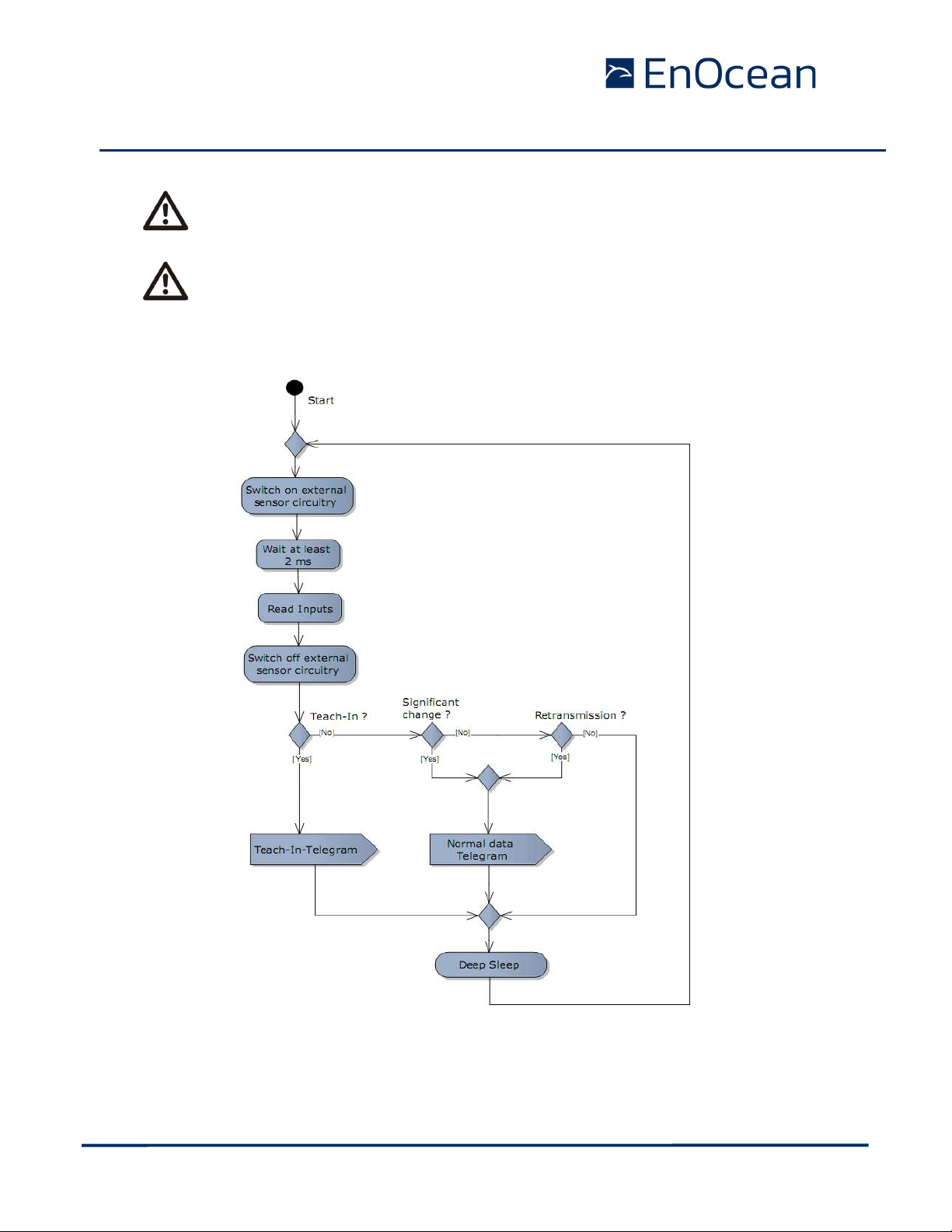
2.1 Simplified firmware flow chart for standard /secure mode
© 2020 EnOcean | www.enocean.com STM 431J User Manual | v3.1 | Sep 2020 | Page 10/ 32
Page 11

USER MANUAL
SET
OCC
RESET
BALUN
Spontaneous
up
Micro
Controller
RF Transmitter
928.35MHz
DOLPHIN
SWPWR
Energy
Storage
VCHAR
VGC
Solar Cell
Transmit
Indicator
Scavenger Transmitter Module
STM 431J (STEPCODE: DE and later)
2.2 Pin out
LRN button
UVDDext
LRN
Power management
wake -
VDD
16.384MHz Oscillator
V4
Whip antenna
HSM
A/D
GND
Energy
Store
1
LED
LRN
The figure above shows the pin out of the 431J modules. The pins are named according to
the naming of the Dolphin V4 core to simplify usage of the DOLPHIN API.
© 2020 EnOcean | www.enocean.com STM 431J User Manual | v3.1 | Sep 2020 | Page 11/ 32
Page 12

USER MANUAL
Scavenger Transmitter Module
STM 431J (STEPCODE: DE and later)
2.3 Pin description and operational characteristics
STM 43xJ
Hardware
Symbol
GND GND Ground connection
VDD VDD Supply voltage 2.1 V – 5.0 V; Start-up voltage: 2.6 V
VCHAR VCHAR Charging input Input for an external energy harvester or a
VGC VGC Voltage Long Term
SWPWR
(= switched
DVDD of
Dolphin V4)
UVDDext
(=UVDD of
Dolphin V4
with 1.8MΩ
in series)
IOVDD (not
available at
pin connector)
RESET
PROG_EN
ADIO0
ADIO1 Not used Internal pull-up; do not connect
ADIO2 Not used Internal pull-up; do not connect
ADIO3 HSM Input for HSM 100 Internal pull-up; leave open or
ADIO4 Not used Internal pull-up; do not connect
STM 43xJ
Function Characteristics
Firmware
Symbol
Supply for programming I/F
Supply for programming I/F if
VDD cannot be
used.3
storage
SWPWR DVDD supply volt-
age regulator output switched via
transistor controlled by Dolphin
V4 ADIO5 pin.
UVDDext
IOVDD
RESET
PROG_EN
Ultra low power
supply voltage
regulator output
GPIO supply voltage
Reset input
Programming I/F
Programming I/F HIGH: programming mode active
SET
Analog input For connection of an external set point di-
Maximum ripple: see 2.6
Not available at pin header.
Recommended supply voltage for
programming 3V
battery. See 2.12.
Recommended supply voltage for
programming 3.3V – 3.6 V
Connection of additional external energy
storage possible. See 2.12
1.8 V. Output current: max. 5 mA.
Supply for external circuitry, available
while not in deep sleep mode. SWPWR is
switched on 0.25 ms before sampling of
inputs and is switched off afterwards.
Not for supply of external circuitry!
For use with WAKE pins only, see section
3.1. Limited to max. 1 µA output current
by internal 1.8 MΩ resistor!
Internal connection to Dolphin V4 DVDD
(typ. 1.8 V)
See 2.3.1
Active high reset (1.8 V)
Fixed internal 10 kΩ pull-down.
LOW: operating mode
Digital input, fixed internal 10 kΩ pulldown.
al. See 3.3
connect HSM 100
3
E.g. if module shall be programmed or configured via pin connector.
If a bed of nails fixture for programming is available VDD should be used instead of VCHAR.
© 2020 EnOcean | www.enocean.com STM 431J User Manual | v3.1 | Sep 2020 | Page 12/ 32
Page 13

USER MANUAL
Scavenger Transmitter Module
STM 431J (STEPCODE: DE and later)
ADIO6 Not used Internal pull-up; do not connect
ADIO7 Programming I/F Leave open
SCSEDIO0 SDA EEPROM pin. SDA – I2C pin
Programming I/F
SCLKDIO1
SCL EEPROM pin. SCL – I2C pin
Programming I/F
WSDADIO2
Programming I/F
RSDADIO3
Programming I/F
WAKE0 OCC Wake input Input for external occupancy button.
Change of logic state leads to wake-up and
transmission of a telegram if correct EEP
selected.
Must be connected to UVDDext or GND!
At time of delivery WAKE0 is connected to
UVDDext via a jumper at the connector.
See also 3.1.
WAKE1 LRN LRN input Change of logic state to LOW leads to
wake-up and transmission of teach-in telegram.
Internal pull-up to UVDD.
See also 2.8.2 and 3.1.
© 2020 EnOcean | www.enocean.com STM 431J User Manual | v3.1 | Sep 2020 | Page 13/ 32
Page 14

USER MANUAL
, do not apply
and the pins of the serial interface (SCSEDIO0,
. This may lead to unpredictable malfunction
See
Scavenger Transmitter Module
STM 431J (STEPCODE: DE and later)
2.3.1 GPIO supply voltage
The IOVDD pin of Dolphin V4 is internally connected to DVDD. For digital communication
with other circuitry therefore a voltage of 1.8 V has to be used. While the module is in deep
sleep mode the microcontroller with all its peripherals is switched off and DVDD, IOVDD,
and SWPWR are not supplied.
If DVDD=0 V and IOVDD is not supplied (e.g. while in sleep mode)
voltage to ADIO0 to ADIO7
SCLKDIO1, WSDADIO2, RSDADIO3)
of the device.
For I/O pins configured as analog pins the IOVDD voltage level is not relevant!
also 2.3.2.
IOVDD
If configured as digital I/O
ADIO0
ADIO1
ADIO2
ADIO3
ADIO4
ADIO5
ADIO6
ADIO7
SCSEDIO0
SCLKDIO1
WSDADIO2
RSDADIO3
2.3.2 Analog and digital inputs
Parameter Conditions / Notes Min Typ Max Units
Analog Input Mode
Single ended
Measurement range
Input coupling DC
Input impedance
Input capacitance
Parameter Conditions / Notes Min Typ Max Units
Digital Input Mode
Input HIGH voltage
Input LOW voltage
Pull up resistor @IOVDD=1.7 … 1.9 V 90 132 200 k
4
For measurement of set point with external set point dial
Internal reference RVDD/2
Interpreted as4 0x00 0xFF
Single ended against
GND @ 1 kHz
Single ended against
GND @ 1 kHz
2/3
1/3
0 RVDD V
10 M
10 pF
V
IOVDD
V
IOVDD
© 2020 EnOcean | www.enocean.com STM 431J User Manual | v3.1 | Sep 2020 | Page 14/ 32
Page 15

USER MANUAL
Scavenger Transmitter Module
STM 431J (STEPCODE: DE and later)
2.3.3 Temperature sensor
Parameter Conditions / Notes Min Typ Max Units
Measurement range 0 40 °C
Accuracy
17 - 27 °C
0 - 40
0.5
1
K
K
2.3.4 Programming Interface
The positions of the pads needed for programming are shown in the layout below.
Number Symbol
1 VDD
2 GND
3 PROG_EN
4 RESET
5 SCSEDIO0
6 SCLKDIO1
7 WSDADIO2
8 RSDADIO3
9 ADIO7
10 ADIO6
Only if in addition
to programming
I/F a serial interface is needed
Top layer
If VDD is not accessible, e.g. because the module shall be programmed via the pin connector, please use VCHAR instead of VDD (see 2.12).
© 2020 EnOcean | www.enocean.com STM 431J User Manual | v3.1 | Sep 2020 | Page 15/ 32
Page 16

USER MANUAL
Scavenger Transmitter Module
STM 431J (STEPCODE: DE and later)
2.4 Absolute maximum ratings (non operating)
Symbol Parameter Min Max Units
VDD Supply voltage at VDD -0.5 5.5 V
VGC Voltage long term storage 2.0 3.3 V
VCHAR Supply voltage from external energy harvester 0 6 V
ICHAR Supply current from external energy harvester 45 mA
GND Ground connection 0 0 V
VINA Voltage at every analog input pin -0.5 2 V
VIND Voltage at RESET, WAKE0/1, and every digital input -0.5 3.6 V
2.5 Maximum ratings (operating)
Symbol Parameter Min Max Units
VDD Supply voltage at VDD and VDDLIM 2.1 5.0 V
VGC Voltage long term storage 2.0 3.3 V
VCHAR Supply voltage from external energy harvester 0 6 V
Supply current from external energy harvester
ICHAR
VCHAR<4 V
4 V<VCHAR<6 V
GND Ground connection 0 0 V
VINA Voltage at every analog input pin 0 2.0 V
VIND Voltage at RESET, WAKE0/1, and every digital input 0 3.6 V
Limited
internally
45
mA
2.6 Power management and voltage regulators
Symbol Parameter Conditions / Notes Min Typ Max Units
Voltage Regulators
VDDR
Ripple on VDD, where
Min(VDD) > VON
UVDD Ultra Low Power supply 1.8 V
RVDD RF supply Internal signal only 1.7 1.8 1.9 V
DVDD Digital supply Internal signal only 1.7 1.8 1.9 V
Threshold Detector
VON Turn on threshold 2.3 2.45 2.6 V
VOFF Turn off threshold
Threshold detector
STM 431J provide an internal ultra low power ON/OFF threshold detector. If VDD > VON, it
turns on the ultra low power regulator (UVDD), the watchdog timer and the WAKE# pins
circuitry. If VDD ≤ VOFF it initiates the automatic shut down of STM 431J. For details of this
mechanism please refer to the Dolphin V4 Core Description documentation.
50 mV
Automatic shutdown if
1.85 1.9 2.1 V
VDD drops below VOFF
pp
© 2020 EnOcean | www.enocean.com STM 431J User Manual | v3.1 | Sep 2020 | Page 16/ 32
Page 17

USER MANUAL
via programming interface
interface
Dolphin V4 Suite, or EOPX2
Scavenger Transmitter Module
STM 431J (STEPCODE: DE and later)
2.7 Configuration via programming interface
Via the programming interface the configuration area can be modified. This provides a lot
more configuration options. These settings are read after RESET or power-on reset only and
not at every wake-up.
The interface is shown in the figure below:
Reset
PROG_EN
USB
USB <=> SPI
SPI
EnOcean provides EOPX2 (EnOcean Programmer, a command line program) and Dolphin
Suite (Windows application for chip configuration, programming, and testing) and the
USB/SPI programmer device as part of the EDK 350 developer´s kit
In Dolphin Suite two configuration tabs for the STM 431J are available. The profile (GP /
EEP) parameters and the module specific security parameters.
Based on Step code a newer version can be avaivable.
In standard case the user only needs to change the profile parameters = communication
profile.
All security parameters of STM 431J are initialized in production. The module specific parameters, key, PSK and RLC are also initialised during production to a random value. If the
module is used with standard Firmware no additional configuration at the security parameters is required. However we provide the security configuration of the keys as option for
developers.
ADIO7
SCSEDIO0
SCLKDIO1
WSDADIO2
RSDADIO3
STM
431J
2.7.1 EEP Configuration
Parameter Configuration
Wake up cycle Value can be set from 1 s to 65534 s – DEFAULT: 100s
Redundant
Retransmission cycle
Threshold values for
Temperature, Set point
Edge of wake 0 pin change causing a telegram transmission
Manufacturer ID and EEP (EnOcean
Equipment Profile)
© 2020 EnOcean | www.enocean.com STM 431J User Manual | v3.1 | Sep 2020 | Page 17/ 32
Min…Max values for random interval
If Min=Max -> random switched off – DEFAULT MIN: 7,
MAX: 14
The values are:
Temperature: default: 0.5 K (raw value 3), unit is ~0.16
K, max 10 K (raw value 62).
Set point Temperature: default: 10 A/D digits. (max is
254)
255 – for any values – means ignore any change.
Every change of a wake pin triggers a wake-up. For
Wake0 pin it can be configured individually if a telegram
shall be sent on rising, falling, both edges or none.
Information about manufacturer and type of device. This
feature is needed for “automatic” interoperability of sensors and actuators or bus systems. Information how to
set these parameters requires an agreement with
EnOcean. Unique manufacturer IDs are distributed by the
Page 18

USER MANUAL
via programming interface
Scavenger Transmitter Module
STM 431J (STEPCODE: DE and later)
EnOcean Alliance.
2.7.2 Security Configuration
Parameter Configuration
Mode There are three options available:
Transport / Secure / Normal
Transport / Secure
Transport / Normal
External EEPROM Present Default is set to yes. If set to no, then the module will
not store the RLC. The Security level format must be
specified not to use RLC, otherwise the RLC will restart
after a power down.
Initialisation of external EEPROM. One time option, must be performed at first start up.
Default Yes.
Pre-shared key usage Default: disabled.
Private Key AES 128 key which is used for data encryption.
Please refer to the Security specification for details on
the Security level format.
Subkey 1 Subkey derivated from private key.
Subkey 2 Subkey derivated from private key.
Pre-shared Key Pre-shared key used for PSK protected teach in.
Set initial RLC Initial value of the RLC.
© 2020 EnOcean | www.enocean.com STM 431J User Manual | v3.1 | Sep 2020 | Page 18/ 32
Page 19

USER MANUAL
Scavenger Transmitter Module
STM 431J (STEPCODE: DE and later)
2.8 Radio telegram
2.8.1 Normal operation – standard and enhanced security mode
In normal operation 431J transmit telegram data according to the selected EEP or GP.
(EnOcean Equipment Profile). In case of STM 431J is in enhanced security mode this telegram is encrypted.
For details please refer to the EnOcean Equipment Profiles specification.
2.8.2 Teach-in telegram - standard and enhanced security mode
In case of a wake-up via WAKE1 pin (LRN input) the module transmits a teach-in telegram.
If the manufacturer code is not set, the module transmits a normal telegram according
to 2.8.1 with the difference that DI_3=0.
If a manufacturer code is set, this teach-in telegram contains special information as described below.
With this special teach-in telegram it is possible to identify the manufacturer of a device
and the function and type of a device. The following EnOcean Equipment Profiles are supported by STM 431J. They have to be selected according to the availability of external occupancy button and set point control by the method described in 2.7:
A5-02-05 Temperature sensor 0-40 °C (default)
A5-10-03 Temperature sensor 0-40 °C, set point control
A5-10-05 Temperature sensor 0-40 °C, set point, and occupancy control
If a HSM 100 module is plugged onto the connector in addition the following EEPs are supported:
A5-04-01 Temperature and humidity sensor 0-40 °C and 0-100% r.h.
A5-10-10 Temperature and humidity sensor 0-40 °C and 0-100% r.h.,
set point control, and occupancy control
A5-10-12 Temperature and humidity sensor 0-40 °C and 0-100% r.h., set point control
For details please refer to the EnOcean Equipment Profiles specification.
If Generic Profiles was selected then in teach-in mode Generic Profiles Teach-in request is
transmitted. Please refer to the Generic Profiles Specification for details [8].
2.9 Secure radio telegram
The STM 431J can be operated in:
Standard mode – no enhanced security is used. This is the common operation mode,
originally available. This is also the default factory mode.
Security mode – communication is protected by enhanced security features. This
mode was added later in module evolution.
2.9.1 Switching between modes
See chapter 2 for details.
2.9.2 Encrypted communication - Enhanced security mode
In enhanced mode the data link content is always protected with advanced security features. Normal operation DL and also Teach-in DL are protected in the same way. The secu-
© 2020 EnOcean | www.enocean.com STM 431J User Manual | v3.1 | Sep 2020 | Page 19/ 32
Page 20

USER MANUAL
Scavenger Transmitter Module
STM 431J (STEPCODE: DE and later)
rity features used are defined by the Security Level format - SLF. This parameter is set by
default to the highest possible level and cannot be changed (Stepcode >=DE):
24-bit RLC, set to 0 at production
RLC tx,
3-byte CMAC,
VAES encryption
To add security features to the communication the Normal operation DL and Teach-in DL
are encapsulated into a secured telegram. The data content of the telegram is not changed.
Please refer to the EnOcean Security Specification [1] for details.
2.9.3 Security Teach-In - Enhanced security mode
To enable security communication the STM 431J has to send a security teach-in telegram to
the other communication partner and so inform him about the used security profile, keys
and initial RLC. The security teach-in has to take place before any other communication can
be executed (profile teach-in included). To trigger the transmission of the teach-in telegram
WAKE1 pin (LRN input) is pressed. The security teach-in telegram is transmitted before the
profile teach-in. The following profile teach-in telegram is already protected by advanced
security features.
The process of sending security teach-in telegram and profile teach-in telegram is triggered
by one pressing of the LRN button.
The behaviour of the LRN button in enhanced mode is following:
1. Button is pressed
2. Security teach-in is send.
3. Profile teach-in is send.
2.9.3.1 PSK Security Teach-in - Enhanced security mode - optional
The Security Teach-in telegram carries the information of KEY and RLC. This information is
either send plain text (as is) or it is protected by the pre-shared key - PSK. The PSK must
be in printed on the transmitting device. To use PSK teach-in, the PSK must be read by the
end-user and entered into the other communication partner. For this purpose the EnOcean
radio interface cannot be used. The PSK can be entered through an user interface or semiautomatized e.g. by a QR code reader.
For details on the PSK Teach-in please refer to the EnOcean Security Specification [1].
PSK feature is disabled by default. To enable PSK feature the execute configuration via programming interface. See chapter 2.7.2 for details.
2.10 Signal telegram
After pressing the LRN button for 5 seconds a signal telegram (data: 0x0E) will be sent and
the module enters the transport mode. Signal telegram is used for the purpose to inform
the nearby receivers this device will stop radio transmission.
For details please refer to the EnOcean Equipment Profiles specification.
(http://www.enocean-alliance.org/eep/)
2.11 Transmit timing
The setup of the transmission timing allows avoiding possible collisions with data packages
of other EnOcean transmitters as well as disturbances from the environment.
Within each transmission cycle, 3 identical sub-telegrams are transmitted within 25 ms.
© 2020 EnOcean | www.enocean.com STM 431J User Manual | v3.1 | Sep 2020 | Page 20/ 32
Page 21

USER MANUAL
Scavenger Transmitter Module
STM 431J (STEPCODE: DE and later)
In case of case of encrypted operation only 2 sub telegrams are transmitted.
The transmission of one sub-telegram lasts approximately 1.2 ms (normal) or 2 ms (secured).
See EnOcean Radio Protocol 2 for detailed timings [8].
© 2020 EnOcean | www.enocean.com STM 431J User Manual | v3.1 | Sep 2020 | Page 21/ 32
Page 22

USER MANUAL
Scavenger Transmitter Module
STM 431J (STEPCODE: DE and later)
2.12 Charging circuitry
The figure below shows the internal charging circuit. It is controlled via the WXODIO pin of
Dolphin V4 which switches according to the status of the internal threshold detector. For
details please refer to the Dolphin V4 Core Description documentation. The WXIDIO pin is
used to disconnect the long term energy storage element at voltages below VOFF to avoid
deep discharge.
C1 is from DE step code changes to MS412FE.
An external 3 V backup battery can be connected at VCHAR.
2.13 Energy consumption
For energy calculations following values are used:
Internal energy storage MS412FE with usable capacity of about 0.7 mAh
https://www.sii.co.jp/en/me/datasheets/ms-rechargeable/ms412fe-5/
(usable voltage range 2.4 - 3 V at 25 °C)
Solar cell ECS 200 delivers at 200 lux about 5 µA
https://www.enocean.com/de/enocean-module/details/ecs-300/
Power consumption transmit cycle standard mode: 100 µAs
Power consumption internal sensor measurement: cycle 30 µAs
Current is proportional to illumination level (not true at very low levels!)
Average leak current of STM 4xy at 25°C: 0.5 uA
Example calculation of the energy consumption with following parameters:
Requirements for example calculation:
configuration: wake cycle 100 s and min. transmit every 10th wake up
8 h light per day (24 h) light @ 200 lux and 25°C
Current consumption (depending on amount of wake-ups due to temperature change):
Min. current consumption with no wake-up cycle due to temperature changes:
30 uAs / 100 s + 100 uAs / 1000 s + 0.5 uA = 0.9 uA
© 2020 EnOcean | www.enocean.com STM 431J User Manual | v3.1 | Sep 2020 | Page 22/ 32
Page 23

USER MANUAL
Scavenger Transmitter Module
STM 431J (STEPCODE: DE and later)
Maximum current consumption with max. wake-up cycles due to temperature
changes :
30 uAs / 100 s + 100 uAs / 100 s + 0.5 uA = 1.8 uA
Average current consumption: (0.9 uA + 1.8 uA) / 2 = 1.35 uA
Average solar power harvested: 5uA / (8 h / 24 h) = 1.67 uA
Time to fully charge energy storage (2.4 to 3.0 V) at stable temperature:
0.7 mAh / (1.67 uA – 0.9 uA) = 909 h = 38 days
Average operation time in darkness when fully charged (3.0 V to 2.4 V):
0.7 mAh / 1.35 uA = 519 h = 22 days
Remarks:
Calculation examples and values have tolerances of about +/- 20%.
Energy storage performance, power consumption and solar cell performance varies
over temperature.
Energy storage performance degrades over life time, especially if energy storage is
long time exposed to very high temperatures. High temperatures will accelerate aging. Very low temperature will temporary reduce capacity of energy store and this
leads to considerable shorter dark time operation
Short wake-up cycles (e.g. 1 s) and transmit intervals (e.g. 1 s) significantly reduce
energy storage performance, for this use case an external power supply is recommended
2.13.1 Consumption in enhanced security mode
Enhanced security mode requires more energy due to encryption algorithm computing time
and extended telegram length because of CMAC and RLC. This added consumption is compensated by reducing the subtelegram count to 2. With this measure the operation in dark
time is even little bit increased.
There it is to assume the operation in dark time is not reduced by using enhanced security.
© 2020 EnOcean | www.enocean.com STM 431J User Manual | v3.1 | Sep 2020 | Page 23/ 32
Page 24

USER MANUAL
at a defined logic level at any
At time of delivery a jumper is connected between WAKE0 and UVDDext.
Dolphin V4
WAKE0
UVDD
STM 431J
LRN Button
Jumper installed at
Scavenger Transmitter Module
STM 431J (STEPCODE: DE and later)
3 APPLICATIONS INFORMATION
3.1 Using the WAKE pins
The logic input circuits of the WAKE0 and WAKE1 pins are supplied by UVDD and therefore
also usable in “Deep Sleep Mode”. Due to current minimization there is no internal pull-up
or pull-down at the WAKE pins. When STM 431J is in “Deep Sleep Mode” and the logic levels of WAKE0 and / or WAKE1 is changed, STM 431J starts up.
As the there is no internal pull-up or pull-down at the WAKE0 pin, it has to be ensured by external circuitry, that the WAKE0 pin is
time.
WAKE1 provides an internal 1.8 MΩ pull-up. See figure below.
WAKE1
1M8
WAKE1
GND
1M8
UVDDext
WAKE0
time of delivery
When the LRN button is pressed WAKE1 is pulled to GND and a teach-in telegram is transmitted. As long as the button is pressed a small current of approximately 1 µA is flowing. It
is possible to connect an additional external button in parallel between WAKE1 and GND if a
different position of the button in the device is required.
WAKE0 is connected to UVDDext via a jumper at time of delivery. If the module is mounted
onto a host PCB the jumper has to be removed. The circuitry on the host PCB then has to
ensure that WAKE0 is always in a defined position. There are two ways to use WAKE0:
Connect WAKE0 to UVDDext and connect an external button between WAKE0 and GND.
As long as the button is pressed a current of 1 µA will flow.
Connect a 3 terminal switch and switch WAKE0 to either GND or UVDDext. In this case
there is no continuous flow of current in either position of the switch.
3.2 Temperature sensor
STM 431J provide an internal temperature sensor which is part of the Dolphin V4 integrated
circuit and measures the chip temperature.
Therefore it is important to provide a good thermal connection of the IC to the environment
by ensuring sufficient ventilation of air inside the housing. Only then the measurement will
represent the ambient temperature.
© 2020 EnOcean | www.enocean.com STM 431J User Manual | v3.1 | Sep 2020 | Page 24/ 32
Page 25

USER MANUAL
STM
431J
HSM 100
STM 431J
SWPWR
GND
ADIO0
10k OCC
UVDDext
Set Point
Occupancy
Scavenger Transmitter Module
STM 431J (STEPCODE: DE and later)
Depending on the design of the housing a delay between ambient temperature changes and
measured temperature value will be seen.
Heating of the chip due to its current consumption is negligible as the chip only
consumes 100 nA while in sleep mode.
Temperature measurement every second is not recommended as in this case effects of heating of the chip might become visible and accuracy is reduced.
3.3 Set point control and occupancy button
In order to control the set point, an external potentiometer has to be connected as shown
below. In addition this figure shows how to connect the occupancy button.
3.4 Combination with humidity sensor module HSM 100
The humidity sensor module HSM 100 extends the functionality of STM 431J temperature
sensor modules.
HSM 100 contains an internal calibrated humidity sensor and can be plugged onto
STM 431J modules via the 20 pin connector. For details please refer to the data sheet of
HSM 100.
© 2020 EnOcean | www.enocean.com STM 431J User Manual | v3.1 | Sep 2020 | Page 25/ 32
Page 26

USER MANUAL
Scavenger Transmitter Module
STM 431J (STEPCODE: DE and later)
3.6 EEPROM Storage for the Rolling code
The STM 431J was developed to be used with internal memory. The EEPROM is connected
to the SDA and SLK pins and it is suited on the PCB of the STM 431. The SWPWR pin controls the power supply of the EEPROM. Please consider that the SWPWR pin also provides
energy to possible external sensor circuit – absolute maximum is
The EEPROM current is typ. 0.1 mA for 5 ms during write operation. For details please refer
to the User Manual of the EEPROM [7] (24AA08).
Circuit of connected EERPOM is following:
5 mA
.
3.7 Antenna layout
3.7.1 Whip antenna
Specification of the whip antenna; L=64 mm
© 2020 EnOcean | www.enocean.com STM 431J User Manual | v3.1 | Sep 2020 | Page 26/ 32
Page 27

USER MANUAL
Glass, wood, concrete, metal
> 2mm
> 5mm
Plastic
Scavenger Transmitter Module
STM 431J (STEPCODE: DE and later)
Antenna layout recommendation
STM 43xJ without host PCB STM 43xJ with host PCB
Glass, wood, concrete, metal
> 1cm
> 2cm
> 2cm
Host PCB
GND plane
3.7.2 Helical antenna (STM 431J)
Antenna recommendation
STM 431J without host PCB STM 431J with host PCB
Host PCB
GND plane
© 2020 EnOcean | www.enocean.com STM 431J User Manual | v3.1 | Sep 2020 | Page 27/ 32
Page 28

USER MANUAL
lease make sure not to exert
and should be
Scavenger Transmitter Module
STM 431J (STEPCODE: DE and later)
3.8 Mounting STM 431J into a housing
The figure below shows an example of a housing into which the module can be mounted
(with antenna pointing to the left).
To avoid damage to the solar cell or the PCB itself, p
shear force (side force within the plane of the solar cell) onto the solar cell!
The maximum vertical force onto the solar cell must not exceed 4 N
homogeneously distributed!
Bending of the PCB must be avoided!
Please make sure that the housing covers 0.5 mm at the solar cell edges.
Within 0.5 mm off the edge flaking is possible due to the cutting process.
© 2020 EnOcean | www.enocean.com STM 431J User Manual | v3.1 | Sep 2020 | Page 28/ 32
Page 29

USER MANUAL
Scavenger Transmitter Module
STM 431J (STEPCODE: DE and later)
3.9 Transmission range
The main factors that influence the system transmission range are type and location of the
antennas of the receiver and the transmitter, type of terrain and degree of obstruction of
the link path, sources of interference affecting the receiver, and “Dead” spots caused by
signal reflections from nearby conductive objects. Since the expected transmission range
strongly depends on this system conditions, range tests should categorically be performed
before notification of a particular range that will be attainable by a certain application.
The following figures for expected transmission range may be used as a rough guide only:
Line-of-sight connections: Typically 30 m range in corridors, up to 100 m in halls
Plasterboard walls / dry wood: Typically 30 m range, through max. 5 walls
Ferroconcrete walls / ceilings: Typically 10 m range, through max. 1 ceiling
Fire-safety walls, elevator shafts, staircases and supply areas should be considered as
screening.
The angle at which the transmitted signal hits the wall is very important. The effective wall
thickness – and with it the signal attenuation – varies according to this angle. Signals
should be transmitted as directly as possible through the wall. Wall niches should be avoided. Other factors restricting transmission range:
Switch mounted on metal surfaces (up to 30% loss of transmission range)
Hollow lightweight walls filled with insulating wool on metal foil
False ceilings with panels of metal or carbon fiber
Lead glass or glass with metal coating, steel furniture
The distance between EnOcean receivers and other transmitting devices such as computers, audio and video equipment that also emit high-frequency signals should be at least 0.5
m.
A summarized application note to determine the transmission range within buildings is
available as download from www.enocean.com.
© 2020 EnOcean | www.enocean.com STM 431J User Manual | v3.1 | Sep 2020 | Page 29/ 32
Page 30

USER MANUAL
Scavenger Transmitter Module
STM 431J (STEPCODE: DE and later)
4 AGENCY CERTIFICATIONS
STM 431J complies with the Japanese radio law and is certified according to ARIB STDT108.
When developing customer specific firmware based on the API for this
module, special care must be taken not to exceed the specified regulatory
limits, e.g. the duty cycle limitations!
Please find more details in the EnOcean Radio Protocol 2 Specification5.
When the product is placed on the Japanese market, it must carry the Specified Radio
Equipment marking as shown below:
5
https://www.enocean.com/fileadmin/redaktion/pdf/tec_docs/EnOceanRadioProtocol2.pdf
© 2020 EnOcean | www.enocean.com STM 431J User Manual | v3.1 | Sep 2020 | Page 30/ 32
Page 31

USER MANUAL
Scavenger Transmitter Module
STM 431J (STEPCODE: DE and later)
5 Label Information
1. Product name - „STM 431J / STM 435J“
2. Step Code „xy“
3. Date Code “KW/YY”: e.g. 15/13
4. Status „D431-z“: e.g 1
5. DMC
6. ARIB Marking, radius 3mm
7. ARIB Marking with number (003-130187)
5.1 QR Code label
5.1.1 Included Information:
[30S00000502CB78+ ZBA2054A875E77768C7740157BDF9CF68+30PS3061-
D431+2PDB08+S01123456123456]
30S00000502CB78 15 CHARS 30S<6 Byte Chip-ID>
+ 1 CHAR
13ZBA2054A…….68 33 CHARS 13Z<32 Digit Key>
+ 1 CHAR
30PS3061-D431 13CHARS 30P<Order code>
+ 1 CHAR
2PDB08 6 CHARS 2P<2 Digit Stepcode><2 Digit Status>
+ 1 CHAR
Sxxyyyyyyyyyyyy 15 CHARS S<2 Digit Hersteller Kennung>
<12 Digit DMC/Seriennummer>
5.1.2 QR-Code Specification
QR-Code Version: 4 (33x33 pixel)
Error Correction Level: M (15% error correction)
Mode: Alphanumeric Mode
Character Capacity: 90
Keep off are around the code: 2 Pixel (UP, Down, Left und Right)
Pixel Size: min. 4x4 points per Pixel
© 2020 EnOcean | www.enocean.com STM 431J User Manual | v3.1 | Sep 2020 | Page 31/ 32
Page 32

USER MANUAL
Scavenger Transmitter Module
STM 431J (STEPCODE: DE and later)
600dpi x 600dpi Resolution:
1 Printpoint: 0.0423mm x 0.0423mm
1 Pixel: 0.1693mm x 0.1693mm
© 2020 EnOcean | www.enocean.com STM 431J User Manual | v3.1 | Sep 2020 | Page 32/ 32
 Loading...