

Page 1

Radio Magnet Contact
STM 250
User Manual V1.3
March 2005
Page 2

Revision History
The following major modifications and improvements have been made to the previous version
of this document (V0.9):
Version Major Changes
V1.0 • Chapter 2.5: The bits LRN and STATE in DATABYTE_3 have been inverted
• Chapter 3.2: Recommendations for suited magnets and positioning added
V1.1 • Chapter 1.5 “Physical Dimensions of Magnet Housing” added
• Chapter 2.6 “Learning” fully revised and renamed
• Chapter 2.3 “Radio Telegram” revised
• Chapter 3.2 “Recommendations for Magnet Positioning” revised
V1.2 • Chapter 2.5: The bits LRN and STATE in DATABYTE_3 have been defined in final:
(LRN=”0”:“LRN-pushbutton pressed” and STATE=”0”:“No magnet presence”)
V1.3 • ESD protection: Note added that STM250 is qualified for the use within building
automation & installation, not for industrial applications (chapter 1.2)
• Switch over time defined to ≥ 80ms (chapter 1.3)
• Cyclic presence signal time defined to 5-30 minutes, typ. 15 min (chapter 1.3)
• Update of Solar Energy Balance Calculation (chapter 1.3 and 2.2)
• Energy storage: Notes added concerning Goldcap configuration and concerning
reduced component life time at continuously operation temperatures higher than
50°C (chapter 2.2)
• Mounting note added, that the receiver unit should not be placed at the same
plane as the STM250 when STM250 is mounted on a metal surface (chapter 3.1)
V1.4 • FCC/IC Approval Requirements added (chapter 3.6)
Published by EnOcean GmbH, Kolpingring 18a, 82041 Oberhaching, Germany
www.enocean.comT, info@enocean.com, phone ++49 (89) 6734 6890
© EnOcean GmbH, all Rights Reserved
Important!
This information describes the type of component and shall not be considered as assured characteristics. No
responsibility is assumed for possible omissions or inaccuracies. Circuitry and specifications are subject to change
without notice. For the latest product specifications, refer to the EnOcean website: http://www.enocean.com.
As far as patents or other rights of third parties are concerned, liability is only assumed for devices, not for the
described applications, processes and circuits.
EnOcean does not assume responsibility for use of devices described and limits its liability to the replacement of
devices determined to be defective due to workmanship. Devices or systems containing RF components must meet the
essential requirements of the local legal authorities.
The devices must not be used in any relation with equipment that supports, directly or indirectly, human health or life
or with applications that can result in danger for people, animals or real value.
Components of the devices are considered and should be disposed of as hazardous waste. Local government
regulations are to be observed.
Packing: Please use the recycling operators known to you. By agreement we will take packing material back if it is
sorted. You must bear the costs of transport. For packing material that is returned to us unsorted or that we are not
obliged to accept, we shall have to invoice you for any costs incurred.
©EnOcean GmbH, A. Anders
Page 2 of 24
STM 250 User Manual V1.3
Page 3

Table of Contents
1. GENERAL DESCRIPTION ______________________________________________________________ 4
T
1.1 Basic Functionality __________________________________________________________________ 4
1.2 Typical Applications_________________________________________________________________ 5
1.3 Features Overview __________________________________________________________________ 5
1.4 Dimensions of Reed Contact Unit __________________________________________________ 6
1.5 Dimensions of Magnet Unit _________________________________________________________ 8
1.6 Environmental Conditions __________________________________________________________ 9
1.7 Ordering Information _______________________________________________________________ 9
2. FUNCTIONAL DESCRIPTION __________________________________________________________ 10
2.1 Block Diagram______________________________________________________________________ 10
2.2 Solar Energy Balance Calculation _________________________________________________ 12
2.3 STM 250 Radio Telegram __________________________________________________________ 15
2.5 Serial Data Communication via Receiver Device RCM 120 _______________________ 17
2.6 Learn Pushbutton – Learning of STM 250 to a Receiver _________________________ 18
3. APPLICATIONS INFORMATION _______________________________________________________ 19
3.1 Unit Mounting ______________________________________________________________________ 19
3.2 Recommendations for Magnet Positioning _______________________________________ 19
3.3 Transmission Range _______________________________________________________________ 21
3.4 CE Approval Requirements ________________________________________________________ 21
3.5 FCC/IC Approval Requirements ___________________________________________________ 22
4. TOOLS __________________________________________________________________________________ 23
4.1 Evaluation Kit EVA 100 ____________________________________________________________ 23
4.2 Field Intensity Meter EPM 100 ____________________________________________________ 23
5. DECLARATION OF CONFORMITY______________________________________________________ 24
©EnOcean GmbH, A. Anders
Page 3 of 24
STM 250 User Manual V1.3
Page 4

T
1. GENERAL DESCRIPTION
STM 250 is a wireless magnet contact. The radio sensor is powered by a small solar
cell and by that it works absolutely maintenance-free. An integrated energy store
allows operation for several days even in total darkness.
The reed contact housing and the magnet housing are very small. This means that
the EnOcean magnet contact is unobtrusively mountable at every window frame
made of aluminum, plastic or wood.
1.1 Basic Functionality
The STM 250 supervises an integrated reed contact and reports every status change
immediately (open<>closed). In addition a sign of life signal is send every 12 minutes.
Energy Store (GOLDCAP)
Teach-in Indication LED
©EnOcean GmbH, A. Anders
Figure 1: Wireless magnet contact STM 250
each-in Pushbutton
Magnet Contact
Figure 2: STM 250 PCB (open case)
Page 4 of 24
(Reed)
Antenna
(Helix)
STM 250 User Manual V1.3
Page 5

1.2 Typical Applications
• STM 250 is designed and qualified for the use in building automation &
installation, not for industrial applications (in cause of ESD protection)
• Typical applications are window, flap and door monitoring
The STM 250 serves the 868 MHz air interface protocol of EnOcean. Together with the serial
interface output of receiver device RCM 120, this product can be easily integrated into
different application-specific system solutions.
The STM device is part of a powerful RF system solution from EnOcean for operation and
control applications. Because the RF transmitters are self-powered (no batteries),
maintenance-free RF systems can be implemented.
1.3 Features Overview
Power supply: ...................................... provided by a optical cell (Solar Power Generator)
Antenna:...................................................................................... internal helix antenna
Frequency / transmission power / modulation type:...... 868.3 MHz / max. 10 mW / ASK
Data rate / channel bandwidth: ...................................................... 120 kbps / 280 kHz
Telegram packet length (sub-telegram):................................................ 0.7 ms +/-5%
No. of (redundant) packets:.................................... 3 – 5 (depending on residual energy)
Transmission range: .................................................... 300m free field, typ. 30m indoor
Device identifier: ............................................... individual 32-bit ID factory-programmed
EnOcean telegram type: ............................................................ 1BS (One Byte Sensor)
Spontaneous wake-up: .........................1 x internal reed contact, switch over time ≥ 80ms
Cyclic Presence signal:...........................................every 5 - 30 minutes, typ. 15 minutes
Sleep mode current consumption: .................................................................. ≈ 25 nA
Operation startup time with empty energy store: ............................ < 10 min @ 400 lx
Illumination time for loading empty energy store to 14h operation in total
darkness: .................................................................. ≈ 5 h @ 1000 lx, ≈ 13 h @ 400 lx
Illumination time for reloading energy store from device working limit to 14h
operation in total darkness: ..................................... < 20 min @ 400 lx, < 1 h @ 100 lx
Maximum operation time during total darkness: ........................................ > 6 days
1)
Energy store is filled up @ 400 lx to 90% of capacity
©EnOcean GmbH, A. Anders
Page 5 of 24
STM 250 User Manual V1.3
1)
Page 6
Teach-in pushbutton: .............................................on-PCB (operating at open case only)
Indicator for teach-in telegram transmission: .................... on-PCB Light Emitting Diode
(beside teach in pushbutton)
A change of the REED CONTACT status or pushing the teach-in button will wake the
transmitter unit to send a radio telegram immediately (reed contact position, teach-in
pushbutton status, unique 32-bit sensor ID, checksum). In addition a PRESENCE SIGNAL is
sent around every 12 minutes to announce the contact status even in case of no input signal
changes (sign of life).
Between the wake-up phases, the device is in sleep mode for minimum power consumption
(on average some nA only!).
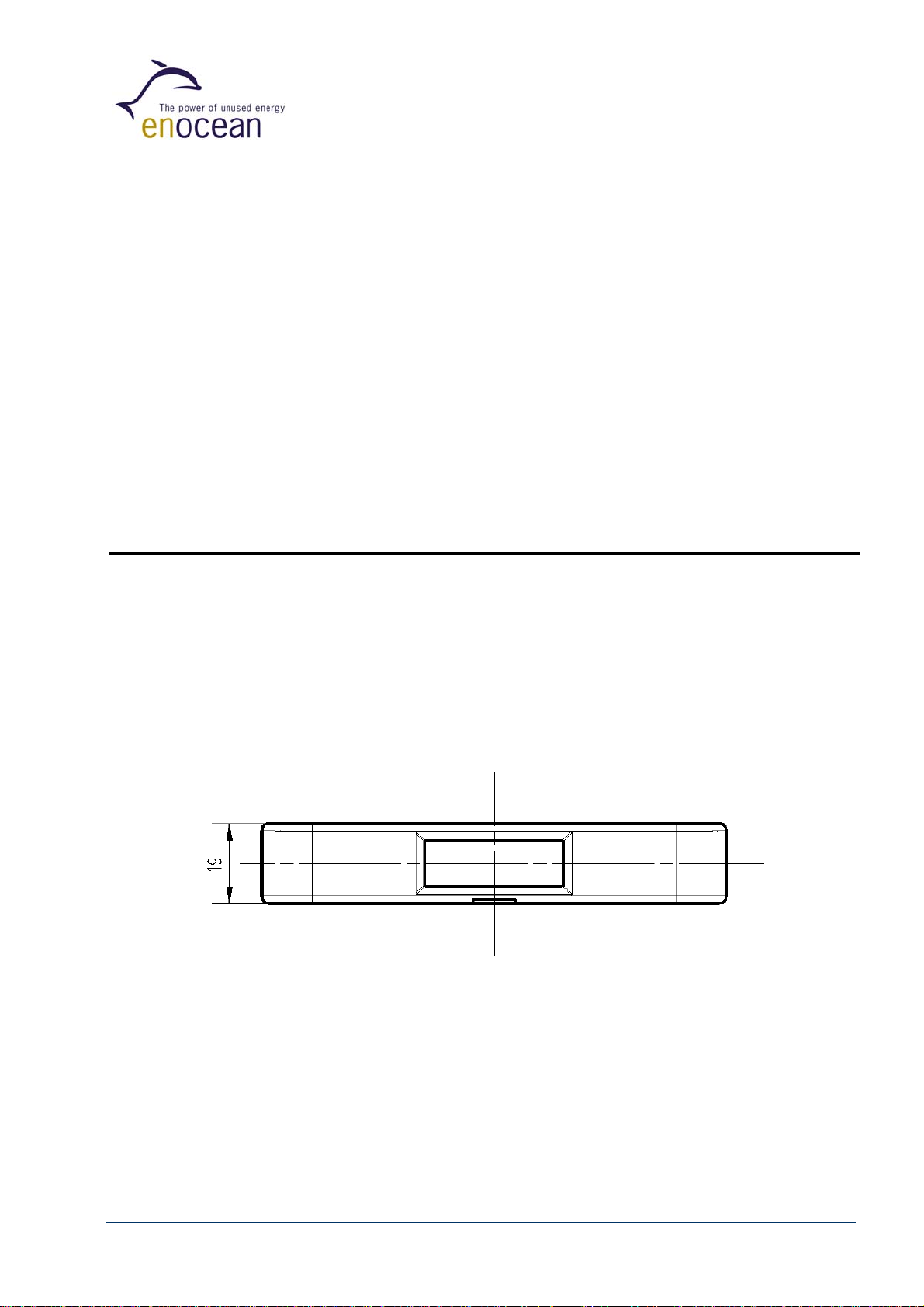
1.4 Dimensions of Reed Contact Unit
Dimensions of Reed Contact Unit: ............................ base 110 x 19 mm x height 15 mm
Weight of Reed Contact Unit: ............................................................................... 18g
Material of housing: ........................................................................................ PC/ABS
Color of housings: ...................................................... signal white (similar to RAL 9003)
Figure 3: Top view
©EnOcean GmbH, A. Anders
Page 6 of 24
STM 250 User Manual V1.3
Page 7
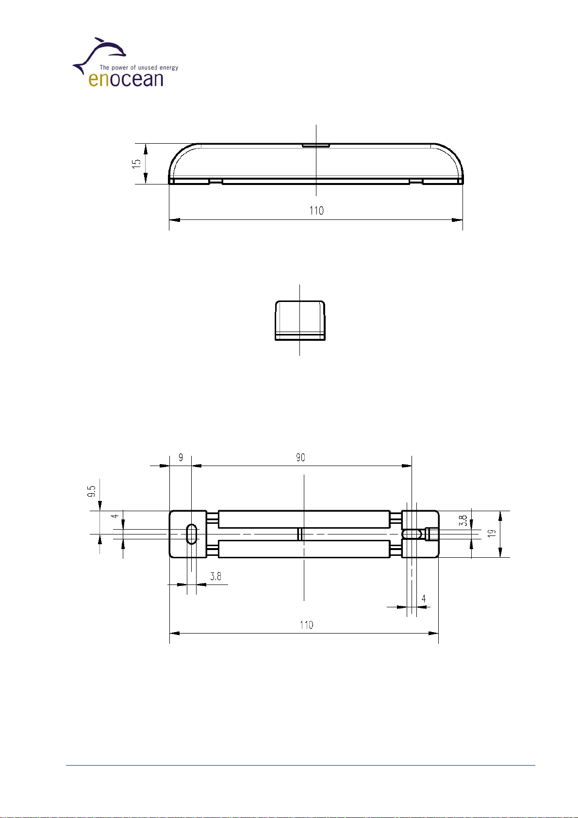
Figure 4: Side view
Figure 5: Front view
©EnOcean GmbH, A. Anders
Figure 6: Bottom view
Page 7 of 24
STM 250 User Manual V1.3
Page 8
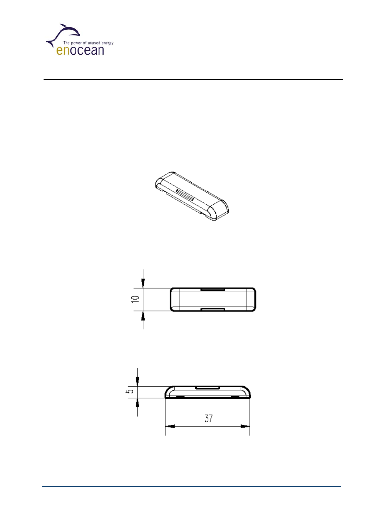
1.5 Dimensions of Magnet Unit
Dimensions of Magnet Unit: .................................. base 37 mm x 10 mm x height 5 mm
Weight of Magnet Unit: .......................................................................................... 2g
Material of housing: ........................................................................................ PC/ABS
Color of housing: ........................................................ signal white (similar to RAL 9003)
Figure 7: Magnet Unit
Figure 8: Top view
©EnOcean GmbH, A. Anders
Figure 9: Side view
Page 8 of 24
STM 250 User Manual V1.3
Page 9

1.6 Environmental Conditions
Figure 10: Front view
Figure 11: Bottom view
Operating temperature: ..................................................................... -25 up to +65 °C
Storage temperature: ..............................-25 up to +65 °C, -40 up to +85 °C for 1h max.
Humidity:............................................................................................................ IP 44
1.7 Ordering Information
Type EnOcean Ordering Code
STM 250
©EnOcean GmbH, A. Anders
S3001-C250
Page 9 of 24
STM 250 User Manual V1.3
Page 10

2. FUNCTIONAL DESCRIPTION
2.1 Block Diagram
Figure 12: STM 250 block diagram
2.1.1 Device power supply: Solar cell and Goldcap energy store
The extremely powerful solar cell has been designed especially for the STM 250 for maximum
unit performance at smallest dimensions. The active solar area is divided into two to provide
independent device power supplies:
a) Small active area: Main power supply
b) Big active area: Gold Cap charging supply
2.1.2 Power control
The power control supervises supply and charging status of the energy store. It controls the
power supply for wake-up timer, microprocessor and HF transmitter.
©EnOcean GmbH, A. Anders
Page 10 of 24
STM 250 User Manual V1.3
Page 11

2.1.3 Wake-up timer / Reed contact / LRN pushbutton
The wake-up timer supervises status changes of the reed contact and learn pushbutton. In
addition, it provides wake-up time intervals for activating the processor.
• Extremely low power consumption during sleeping time period (approx. 25nA).
• The sleep mode is terminated immediately
1. by changing the status of the differential reed contact or
2. when pushing the learn pushbutton.
• Cyclic processor wake-up time strongly depends e.g. on the Goldcap charging status.
2.1.4 Processor
Controls all functionalities after wake-up: First, the status of the reed contact (Open/Closed)
and the LRN pushbutton are sampled. After that RF signal transmission is triggered. If the LRN
pushbutton has been pressed, the output LED is activated for indicating LRN signal sending.
2.1.5 RF transmitter
The radio transmitter is powered up by the processor and sends
• 32-bit ID
• Status of the Reed Contact (open/closed)
• Status of the LRN pushbutton (pressed/released)
©EnOcean GmbH, A. Anders
Page 11 of 24
STM 250 User Manual V1.3
Page 12

2.2 Solar Energy Balance Calculation
In the following diagrams, you will find the energy store operation characteristics under the
condition that the number of reed contact operations can be neglected compared to
cyclic sending times of the presence signal (normal operation in practice). Negligible
implies that reed contact operations are less than 10 times a day.
Notes:
• Configuration of the Goldcap energy store: To obtain the Goldcap nominal capacity
some charging/discharging cycles are needed. Because of that, the initial operating
time at total darkness could be shorter as given below.
• Continuously operation at temperatures higher than 50°C could decrease the capacity
of the Goldcap during lifetime. This will result in shorter charging times and shorter
operating times in total darkness.
2.2.1 Initial loading time for one-night operation
Illumination time for loading empty energy store
to 14 h operation in total darkness (typ. values)
20
16
12
8
loading time [hours]
4
0
100 1000
illumination [lux]
Figure 13
©EnOcean GmbH, A. Anders
Page 12 of 24
STM 250 User Manual V1.3
Page 13

2.2.2 Reload time for one-night operation
Illumination time for reloading energy store from working limit
to 14 h operation in total darkness (typ. values)
40
30
20
reload time [minutes]
10
0
100 1000
illumination [lux]
Figure 14
2.2.3 Initial load time for filling energy store to capacity
Load time STM 250 versus illumination of Goldcap
from working limit to 90% of max. loading voltage (typ. values)
7
6
5
4
3
load time [hours]
2
1
100 200 300 400 500 600 700 800 900 1000
illumination [Lux]
Figure 15
©EnOcean GmbH, A. Anders
Page 13 of 24
STM 250 User Manual V1.3
Page 14

2.2.4 Maximum operation time in total darkness
STM 250 operation time in total darkness (typ. values,
initial loading of Goldcap is 90% of max. loading voltage)
10
8
6
4
operation time [days]
2
0
100 1000
illuminance on average [Lux]
Figure 16
©EnOcean GmbH, A. Anders
Page 14 of 24
STM 250 User Manual V1.3
Page 15

2.3 STM 250 Radio Telegram
For the transmission of the telemetric signals, EnOcean has defined a new dynamic radio data
telegram that is adapted to the individual application. It is optimized to the essential features
of energy autarkic radio sensors:
• Minimal energy demand
• Possibility of operating hundred of senders within the same radio cell
• Maximum transmission reliability
• Wide transmission range
• Easy extensibility
• Suitable for uni- and bi-directional communication
• Flexibility for adaptation of different data structures and data quantities
• Data encryption option
2.3.1 Frequency range and transmission cycle allowed
The EnOcean technology operates the 868.3 MHz radio channel (868.0 – 868.6 MHz), which is
exclusively released for short-time data transmission in Europe. Timing conditions can be
found in chapter 3.5 of this paper.
Because of the very low radiated field strength on average, the 868.3 MHz EnOcean radio
technology can be approved in the USA and in Canada. Timing conditions can be found in
chapter 3.6 of this paper.
2.3.2 Modulation process
As modulation process, EnOcean uses incoherent amplitude modulation (ASK). Digital
amplitude modulation enables the implementation of very efficient energy-saving transmitters
because only the “1”-bits are transferred. At the same interference signal level, the
transmission security of the alternative method (FSK) is identical to that of the ASK method
(Ref: Pehl, Digitale und analoge Nachrichtenübertragung, Hüthig 2001).
2.3.3 Transmission timing
The transmission timing of the radio device STM 250 has been developed to avoid possible
collisions with data packages of other EnOcean transmitters as well as disturbances from the
environment.
With each transmission cycle, 3 identical subtelegrams are transmitted. The transmission of a
subtelegram lasts approximately 0.9 ms. To optimize data security, each telegram is repeated
twice within about 40 ms, whereas the delay between the three transmission bursts is effected
at random.
©EnOcean GmbH, A. Anders
Page 15 of 24
STM 250 User Manual V1.3
Page 16

Fix:
12..27ms
(-25...65°C)
Variable:
0..9.5 ms
(16 slots)
Fix:
12..27ms
(-25...65°C)
t
Figure 17: STM 250 radio timing
2.3.4 Reliable radio transmission within systems operating many sensors
The very short telegrams of EnOcean transmitters enable the operating of a large number of
senders within the same radio cell; the error rate caused by telegram collisions remains
extremely low. Statistically viewed, the transmission reliability is still greater than 99.99% in
the case of 100 radio sensors that transmit once every minute. This means that even large
office buildings and also huge industrial facilities can be equipped with a large number of
sensors of this kind of radio technology.
EnOcean
radio switch
Typical
radio switch
Figure 18: Transmission reliability caused by radio data collision
for EnOcean light switch transmitter
©EnOcean GmbH, A. Anders
Page 16 of 24
STM 250 User Manual V1.3
Page 17

2.5 Serial Data Communication via Receiver Device RCM 120
The RCM 120 Receiver Device of EnOcean enables standard asynchronous communication to
a micro-controller or personal computer with a decompressed and simple data structure (9600
bps, 1 start bit, 8-bit data byte with LSB first, 1 stop bit).
Figure 19: Receiver device RCM 120
When the RCM 120 receiver is set to Mode 0 “Serial Interface”, it transfers out data blocks of
information from the received RF telegrams. For a complete transmitter message, a telegram
of 14 data bytes is transferred via the serial link. The data block format is explained in detail in
the RCM 110/120 User Manual.
Type of STM 250 protocol is “1BS” (One Byte Sensor):
ORG byte = 6 dec. always (EnOcean device type “1BS”)
DATA_BYTE3 as follows:
Bit 7 Bit 3 Bit 0
Reserved LEARN Reserved STATE
Bit 0: STATE
STATE = 1: magnet present (Window CLOSED)
STATE = 0: no magnet (Window OPEN)
Bit 3: LEARN
LEARN = 1: LRN pushbutton not pressed
LEARN = 0: LRN pushbutton pressed
Bits 2..3 and Bits 4..7: reserved
DATA_BYTE2 = 0
DATA_BYTE1 = 0
DATA_BYTE0 = 0
ID_BYTE3 = device identifier (Byte3)
ID_BYTE2 = device identifier (Byte2)
ID_BYTE1 = device identifier (Byte1)
ID_BYTE0 = device identifier (Byte0)
©EnOcean GmbH, A. Anders
Page 17 of 24
STM 250 User Manual V1.3
Page 18

STATUS byte as follows:
Bit 7 Bit 3 Bit 0
Reserved RP_COUNTER
Bits 0..3: RP_COUNTER
RP_COUNTER = 0: original telegram
RP_COUNTER > 0: repeated telegram
Bits 4..7: reserved
2.6 Learn Pushbutton – Learning of STM 250 to a Receiver
If necessary, the sensor radio transmitter STM 250 can be easily made known to the receiver
RCM 120 – that has been set into learn mode – by simply triggering a STM 250 radio signal,
for example by operating the LRN pushbutton. STM 250 devices that are currently known to
the RCM 120 receiver or that are already known by the receiver are signed within H_SEQ of
the serial telegram. For details, see the RCM 110/120 User Manual, but please pay attention to
the following:
There are two fundamental methods for transmitter assignments to a receiver:
1.) Manual input of the transmitter ID into the receiver system
2.) The receiver system automatically learns the ID of a received radio telegram within a
special Learn Mode routine.
In the second case, note that cyclic sending sensors can be unintentionally learned,
especially if there are some sensors in operation at the same time. Because of that, it is
recommended to implement a learn procedure in the system that reacts to a dedicated “Learn
Telegram” only.
This special learn procedure has to be implemented by the system intelligence after
RCM 120 serial interface (the RCM 120 learning procedure does not support the STM
250 Learn-Pushbutton!).
The STM 250 Learn Telegram is characterized by the unambiguous defined Bit 3 within
DATA_BYTE3.
©EnOcean GmbH, A. Anders
Page 18 of 24
STM 250 User Manual V1.3
Page 19

3. APPLICATIONS INFORMATION
3.1 Unit Mounting
Both the EnOcean Reed Contact as well as the EnOcean Magnet are very thin and flat. This
means that the unit is unobtrusively mountable at every window or doorframe made of
aluminum, plastic or wood.
Mounting position of the Reed Contact is horizontal, vertically or even tilted. The arrow signs
on the base of the Reed Contact should be directed downwards. In this mounting position, the
STM 250 housing offers protection against splashing water drops (IP44).
Recommendation for mounting the STM250 on metal surfaces or window frames of
aluminum:
Please note that a radi o receiver unit (e.g. RCM 120) should not be mounted in the
same plane than the STM 250 base plate is mounted, because in extension of the
metal surface the transmission range is reduced by physical radio transmission
effects of the antenna near to metal. For example the receiver should not be
mounted at the window front side.
3.2 Recommendations for Magnet Positioning
The flat magnet should be positioned by facing the housing in the middle of the reed contact
marking as follows:
Reed contact marking
Figure 20: Righted positioning of the Magnet
(Typical for window mounting)
The magnet can be positioned in vertical or in horizontal position to the Reed Contact housing.
The distance between housing and magnet should be less than 5 mm.
©EnOcean GmbH, A. Anders
Page 19 of 24
STM 250 User Manual V1.3
Page 20

Reed contact marking
Figure 21: Planar positioning of the Magnet
(Typical for door mounting)
The round-pole magnet can be removed from the magnet housing. This enables smart
embedding into wooden window casements in square position to the Reed Contact housing.
But note that the round-pole must be mounted beside the reed contact marking, as follows:
or:
Figure 22: Pole-faced positioning of Magnet
(Typical for mounting at wooden window casements)
The distance between housing and magnet should be less than 4 mm when using this
mounting position.
©EnOcean GmbH, A. Anders
Page 20 of 24
STM 250 User Manual V1.3
Page 21

3.3 Transmission Range
The main factors that influence the system transmission range are type and location of the
antennas of the receiver and the transmitter, type of terrain and degree of obstruction of the
link path, sources of interference affecting the receiver, and “dead” spots caused by signal
reflections from nearby conductive objects. Since the expected transmission range strongly
depends on this system conditions, range tests should categorically be performed before
notification of a particular range that will be attainable by a particular application.
The following figures for expected transmission range are considered by using the STM 250
radio transmitter device and the RCM 120 radio receiver device with the provided whip
antennas and may be used as a rough guide only:
- 30 m for obstructed environment (e.g. inside a building)
- 300 m for unobstructed environment (free space propagation)
Further notes to determine the transmission range within buildings are available as download
www.enocean.com.
from
3.4 CE Approval Requirements
The devices bear the EC conformity marking CE and conform to the R&TTE EU-directive on
radio equipment. The assembly conforms to the European and national requirements of
electromagnetic compatibility. The conformity has been proven and the according
documentation has been deposited at EnOcean. The devices can be operated without
notification and free of charge in the area of the European Union, in Switzerland, in Croatia, in
Cyprus, in Czech, in Estonia, in Hungary, in Latvia, in Lithuania, in Malta, in Poland, in
Romania and in Slovenia. The following provisos apply:
• EnOcean RF devices must not be modified or used outside their specification
limits.
• EnOcean RF devices may only be used to transfer digital or digitized data. Analog
speech and/or music are not permitted.
• EnOcean RF devices must not be used with gain antennas, since this may result
in allowed ERP or spurious emission levels being exceeded.
• The final product incorporating EnOcean RF devices must itself meet the essential
requirement of the R&TTE Directive and a CE marking must be affixed on the final
product and on the sales packaging each. Operating instructions containing a
Declaration of Conformity has to be attached.
• If the STM 250 transmitter is used according to the regulations of the 868.3 MHz
band, a so-called “Duty Cycle” of 1% per hour must not be exceeded. Permanent
transmitters such as radio earphones are not allowed. For approval aspects, it
must be ensured that the STM 250 reed contact is not operated more than
13.000 times per hour (e.g. window opened or window closed). For this
calculation the extraordinary short telegram length is considered including all
subtelegrams (see Chapter 2.3.3). Also a tolerance of 5% in telegram length is
included.
©EnOcean GmbH, A. Anders
Page 21 of 24
STM 250 User Manual V1.3
Page 22

3.5 FCC/IC Approval Requirements
This device complies with Part 15 of the FCC Rules and with RSS-210 of Industry Canada. If
this device is operated in compliance with the following requirements it can be operated
without notification and free of charge in the area of the United States of America and in
Canada. Operation is subject to the following two conditions:
(1) this device my not cause harmful interference, and
(2) this device must accept any interference received, including interference that
may cause undesired operation.
Trade Name: STM 250
Model No: STM 250
IC: 5713A-STM250
This device complies with Part 15 of the FCC Rules and with RSS-210 of Industry
Canada. Operation is subject to the following two conditions. (1) this device my not
cause harmful interference, and (2) this device must accept any interference
received, including interference that may cause undesired operation.
FCC ID: SZV-STM250
Warning: Changes or modifications made to this equipment not expressly approved by
EnOcean may void the FCC authorization to operate this equipment.
This equipment has been tested and found to comply with the limits for a Class B digital
device, pursuant to Part 15 of the FCC Rules. These limits are designed to provide reasonable
protection against harmful interference in a residential installation.
This equipment generates, uses and can radiate radio frequency energy and, if not installed
and used in accordance with the instructions, may cause harmful interference to radio
communications.
However, there is no guarantee that interference will not occur in a particular installation. If
this equipment does cause harmful interference to radio or television reception, which can be
determined by turning the equipment off and on, the user is encouraged to try to correct the
interference by one or more of the following measures:
• Reorient or relocate the receiving antenna.
• Increase the separation between the equipment and receiver.
• Connect the equipment into an outlet on a circuit different from that to which the
receiver is connected.
• Consult the dealer or an experienced radio/TV technician for help.
Due to FCC 15.231 operational and timing requirements, the STM 250 magnet contact must
not be operated more than 1414 times per hour (opened or closed):
• Total duration of transmissions must not exceed more than two seconds per hour
• STM250 packet length is 0.9 ms, 3 redundant packets, tolerance of 5% in packet
length, 50% on average packet Ton/Toff ratio
©EnOcean GmbH, A. Anders
Page 22 of 24
STM 250 User Manual V1.3
Page 23

4. TOOLS
4.1 Evaluation Kit EVA 100
EVA 100 is an evaluation kit to support a simple setting-up
operation of the receiver side when the EnOcean sensor
transmitter device STM 250 is evaluated. EVA 100 supports a
rapid evaluation of the RCM 120 serial receiver mode (e.g. via
PC monitor) and supports the fast development of
applications.
Type EnOcean Ordering Code Scope of supply
EVA 100
H3004-G100 • Evaluation board EVA-PCB
• EnOcean radio devices STM 100, PTM
100, RCM 110 and RCM 120
• CD with RS232 PC-link monitor software
and detailed kit documentation
• Wall power supply for EVA-PCB
• Convenient equipment case
4.2 Field Intensity Meter EPM 100
The EPM100 is a mobile field-intensity meter that helps the engineer to find the best
installation positions for sensor and receiver. It can also be used to check disturbances in links
to already installed equipment. The EPM100 displays the field intensity of received radio
telegrams and interfering radio signals in the 868MHz range.
The simplest procedure for determining
the best installation positions for the
radio sensor/receiver:
• Person 1 operates the radio
sensor and generates pushbutton
radio telegrams.
• Person 2 checks the received field
intensity on the meter display to
find the optimal installation
position.
©EnOcean GmbH, A. Anders
Page 23 of 24
STM 250 User Manual V1.3
Page 24

5. DECLARATION OF CONFORMITY
Available with start of volume production
©EnOcean GmbH, A. Anders
Page 24 of 24
STM 250 User Manual V1.3
 Loading...