

Page 1

USER MANUAL
PTM 535 / PTM 535U / PTM 535J – ENOCEAN TRANSMITTER MODULE
© 2019 EnOcean | www.enocean.com F-710-017, V1.0 PTM 535 / 535J User Manual | v1.5 | September 2020 | Page 1/36
Patent protected:
WO98/36395, DE 100 25 561, DE 101 50 128,
WO 2004/051591, DE 103 01 678 A1, DE 10309334,
WO 04/109236, WO 05/096482, WO 02/095707,
US 6,747,573, US 7,019,241
Observe precautions! Electrostatic sensitive devices!
PTM 535 / PTM 535U / PTM 535J
EnOcean Transmitter Module
21.09.2020
Page 2

USER MANUAL
PTM 535 / PTM 535U / PTM 535J – ENOCEAN TRANSMITTER MODULE
© 2019 EnOcean | www.enocean.com F-710-017, V1.0 PTM 535 / 535J User Manual | v1.5 | September 2020 | Page 2/36
REVISION HISTORY
The following major modifications and improvements have been made to this document:
Version
Author
Reviewer
Date
Major Changes
1.0
MKA
MKA
23 May 2018
Initial Release
1.1
MK/CB
CB
02 Aug 2018
Configuration set and functional block
diagram updated, additional minor
changes e.g. ARIB ID added, Tx range
free field 300m
1.2
MK/CB
CB
14 Sep 2018
Renamed Pad 13 from VCC to
VCC_MODE, V+ for configuration only,
hint for PTM Config help
1.3
MK/CB
CB
21 Nov 2018
4.4 added strict sequence and tool requirements for configuration change,
2.3 added CFG test pin
1.4
MK/CB
CB
27 May 2019
Document branding changed, 2.2 pin out
image corrected
1.5
MKA
MKA
21 Sep 2020
FCC / ISED added
Published by EnOcean GmbH, Kolpingring 18a, 82041 Oberhaching, Germany
www.enocean.com, info@enocean.com, phone +49 (89) 6734 6890
© EnOcean GmbH, All Rights Reserved
Important!
This information describes the type of component and shall not be considered as assured
characteristics. No responsibility is assumed for possible omissions or inaccuracies. Circuitry
and specifications are subject to change without notice. For the latest product specifications, refer to the EnOcean website: http://www.enocean.com.
As far as patents or other rights of third parties are concerned, liability is only assumed for
modules, not for the described applications, processes and circuits.
EnOcean does not assume responsibility for use of modules described and limits its liability
to the replacement of modules determined to be defective due to workmanship. Devices or
systems containing RF components must meet the essential requirements of the local legal
authorities.
The modules must not be used in any relation with equipment that supports, directly or
indirectly, human health or life or with applications that can result in danger for people,
animals or real value.
Components of the modules are considered and should be disposed of as hazardous waste.
Local government regulations are to be observed.
Packing: Please use the recycling operators known to you.
Page 3

USER MANUAL
PTM 535 / PTM 535U / PTM 535J – ENOCEAN TRANSMITTER MODULE
© 2019 EnOcean | www.enocean.com F-710-017, V1.0 PTM 535 / 535J User Manual | v1.5 | September 2020 | Page 3/36
TABLE OF CONTENT
1 General description ........................................................................................ 5
1.1 Product description ........................................................................................ 5
1.2 Product variants ............................................................................................ 5
1.3 Technical data ............................................................................................... 6
1.4 Maximum ratings for input signals ................................................................... 6
1.5 Physical dimensions ....................................................................................... 6
1.6 Device drawing ............................................................................................. 7
1.7 Environmental conditions ............................................................................... 8
1.8 Ordering information ..................................................................................... 8
2 Functional description .................................................................................... 9
2.1 Functional Principle ........................................................................................ 9
2.2 Block diagram ............................................................................................... 9
2.3 Interface pin layout ..................................................................................... 10
2.4 Interface pin functionality ............................................................................. 11
3 Radio telegram format ................................................................................. 12
3.1 Standard mode ........................................................................................... 12
3.2 Enhanced security mode .............................................................................. 14
3.3 Switching between operation modes .............................................................. 15
3.4 Transmission timing ..................................................................................... 15
4 PTM 535 configuration ................................................................................. 16
4.1 PTM 535 configuration parameters ................................................................ 16
4.2 PTM 535 configuration interface .................................................................... 17
4.3 PTM 535 test point location ........................................................................... 17
4.4 Connection between Segger J-Link and PTM 535 ............................................. 18
4.4.1 Segger power supply (6-Pin interface) .................................................... 18
4.4.2 External power supply (4 pin configuration interface) ............................... 19
4.5 Required tools ............................................................................................. 20
4.6 Configuration setup ..................................................................................... 21
4.7 User Interface ............................................................................................. 21
4.8 Execution sequence ..................................................................................... 22
5 Application information ................................................................................ 23
5.1 Connection to ECO 200 energy harvester ....................................................... 23
5.2 How to populate a teach-in button (for enhanced security mode) ...................... 23
5.3 Antenna specification ................................................................................... 24
5.4 Layout recommendations ............................................................................. 25
5.5 Transmission range ..................................................................................... 26
6 Regulatory information ................................................................................. 27
6.1 RED (European Union) ................................................................................. 27
6.2 FCC (United States) ..................................................................................... 28
6.2.1 FCC grant of equipment authorization .................................................... 28
6.2.2 FCC regulatory statement ..................................................................... 29
6.3 ISED (Canada) ............................................................................................ 30
6.3.1 ISED technical acceptance certificate...................................................... 30
6.3.2 ISED regulatory statement .................................................................... 32
6.3.2.1 English version ................................................................................. 32
6.3.2.2 French version .................................................................................. 33
6.4 ARIB (Japan) .............................................................................................. 34
Page 4

USER MANUAL
PTM 535 / PTM 535U / PTM 535J – ENOCEAN TRANSMITTER MODULE
© 2019 EnOcean | www.enocean.com F-710-017, V1.0 PTM 535 / 535J User Manual | v1.5 | September 2020 | Page 4/36
6.4.1 ARIB (Japan) certificate ........................................................................ 34
6.4.2 ARIB (Japan) regulatory requirements .................................................... 35
7 Product history ............................................................................................ 36
Page 5
USER MANUAL
PTM 535 / PTM 535U / PTM 535J – ENOCEAN TRANSMITTER MODULE
© 2019 EnOcean | www.enocean.com F-710-017, V1.0 PTM 535 / 535J User Manual | v1.5 | September 2020 | Page 5/36
1 General description
1.1 Product description
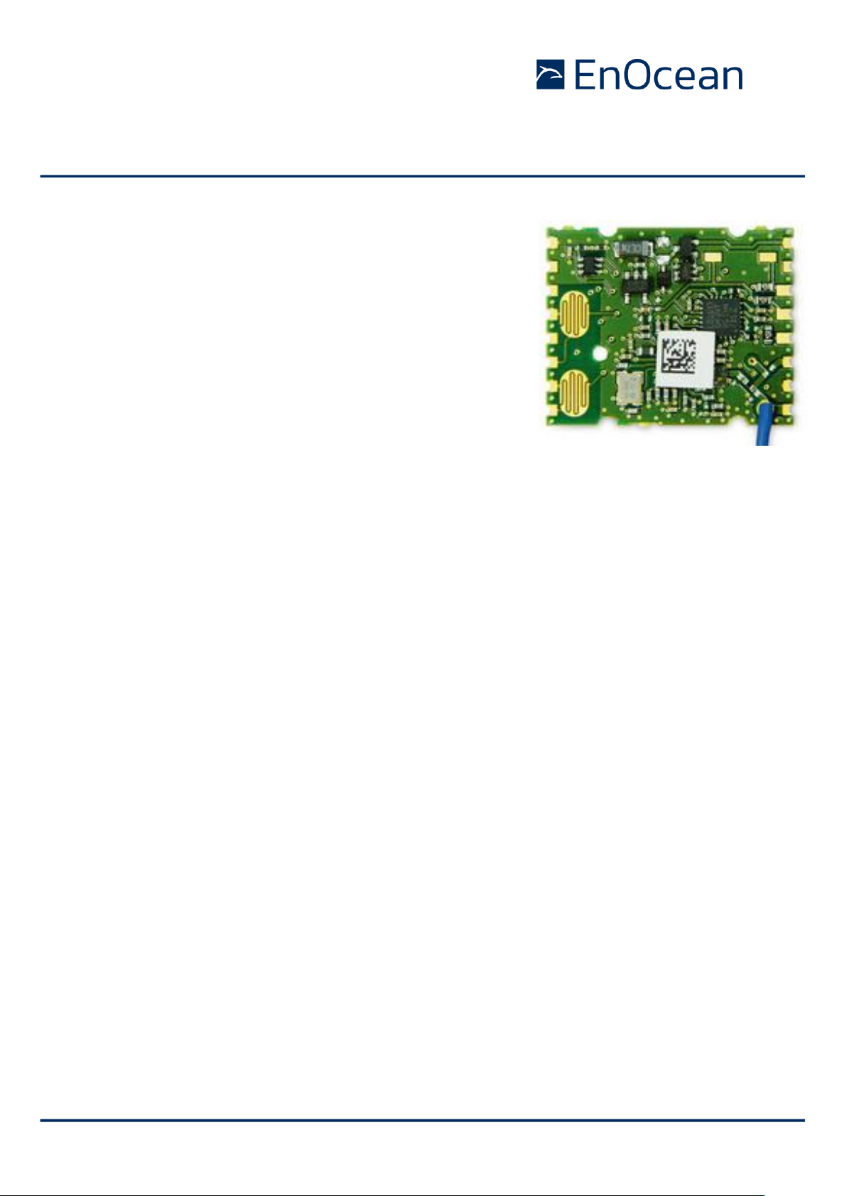
The radio transmitter module PTM 535, PTM 535U and PTM
535J from EnOcean enable the implementation of wireless
sensors and switches without batteries.
Key applications are handheld remote controls or industrial
switches.
1.2 Product variants
The following product variants are offered:
◼ PTM 535
Operating frequency 868.300 MHz
◼ PTM 535U
Operating frequency 902.875 MHz
◼ PTM 535J
Operating frequency 928.350 MHz
All three variants contain a pre-installed whip antenna, support enhanced security and are
delivery in a cardboard box. The term “PTM 535” is subsequently used to describe all three
product variants unless otherwise noted.
Page 6

USER MANUAL
PTM 535 / PTM 535U / PTM 535J – ENOCEAN TRANSMITTER MODULE
© 2019 EnOcean | www.enocean.com F-710-017, V1.0 PTM 535 / 535J User Manual | v1.5 | September 2020 | Page 6/36
1.3 Technical data
Power supply ECO 200 or equivalent energy pulse
Antenna Pre-installed whip antenna
Frequency / Modulation / Transmission power
PTM 535 868.300 MHz / ASK / +5 dBm
PTM 535U 902.875 MHz / FSK / +4 dBm
PTM 535J 928.350 MHz / FSK / +0 dBm
Data rate 125 kbps
Telegram type RPS Type 2
SEC (Encrypted and authenticated transmission)
Digital inputs 4 (2 of those also usable via meander contacts)
Mode selection (standard / enhanced security) 3 pins / LRN Button
Transmission range up to 300 m free field, up to 30 m indoor
1.4 Maximum ratings for input signals
Symbol
Parameter
Min
Max
Units
AC1, AC2
Supply voltage operation
0
6.0
V
V+
Supply voltage configuration
0
5.5
V
GND
Voltage on GND pin
0 0 V
A0, A1, B0, B1,
SECURE, STANDARD, CFG
Voltage on digital input pins
0
3.6
V
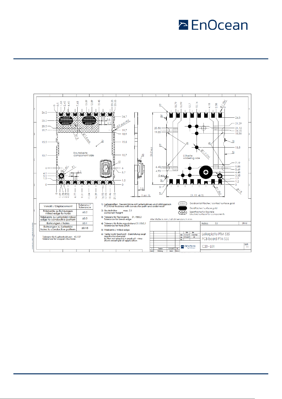
1.5 Physical dimensions
PCB dimensions 26.2 x 21.15 x 3.5 mm
Page 7
USER MANUAL
PTM 535 / PTM 535U / PTM 535J – ENOCEAN TRANSMITTER MODULE
© 2019 EnOcean | www.enocean.com F-710-017, V1.0 PTM 535 / 535J User Manual | v1.5 | September 2020 | Page 7/36
1.6 Device drawing
Figure 1 – PTM 535 outline
Page 8

USER MANUAL
PTM 535 / PTM 535U / PTM 535J – ENOCEAN TRANSMITTER MODULE
© 2019 EnOcean | www.enocean.com F-710-017, V1.0 PTM 535 / 535J User Manual | v1.5 | September 2020 | Page 8/36
1.7 Environmental conditions
Operating temperature -25 °C … +65 °C
Storage temperature -40 °C … +85 °C
Storage temperature in Tape & Reel -20 °C … +50 °C
Humidity 0% … 93% r.h., non-condensing
1.8 Ordering information
Type
Ordering
Code
Frequency
Note
PTM 535
S3001-A535
868.300 MHz
Whip antenna, Delivered in cardboard box
PTM 535U
S3051-A535
902.875 MHz
Whip antenna, Delivered in cardboard box
PTM 535J
S3061-A535
928.350 MHz
Whip antenna, Delivered in cardboard box
Page 9
USER MANUAL
PTM 535 / PTM 535U / PTM 535J – ENOCEAN TRANSMITTER MODULE
© 2019 EnOcean | www.enocean.com F-710-017, V1.0 PTM 535 / 535J User Manual | v1.5 | September 2020 | Page 9/36
2 Functional description
2.1 Functional Principle
PTM 535 is designed to be powered by an ECO 200 kinetic energy harvester from EnOcean.
PTM 535 can be mechanically connected to the contact springs of ECO 200 by means of its
integrated PCB contacts.
PTM 535 provides 4 digital input pads and two PCB meander structures allowing the implementation of push button functions either via external connection or via conductive rubber
pads.
When the ECO 200 harvester generates an energy pulse or when power is supplied by another source then PTM 535 determines the polarity of the energy pulse (push or release
direction), and the operating status of the digital inputs and encodes this information in an
RF telegram.
The communication mode (enhanced security communication or standard communication)
can be selected using the SECURE and STANDARD input pins or the LRN button (which is
not mounted by default). Default communication mode is STANDARD.
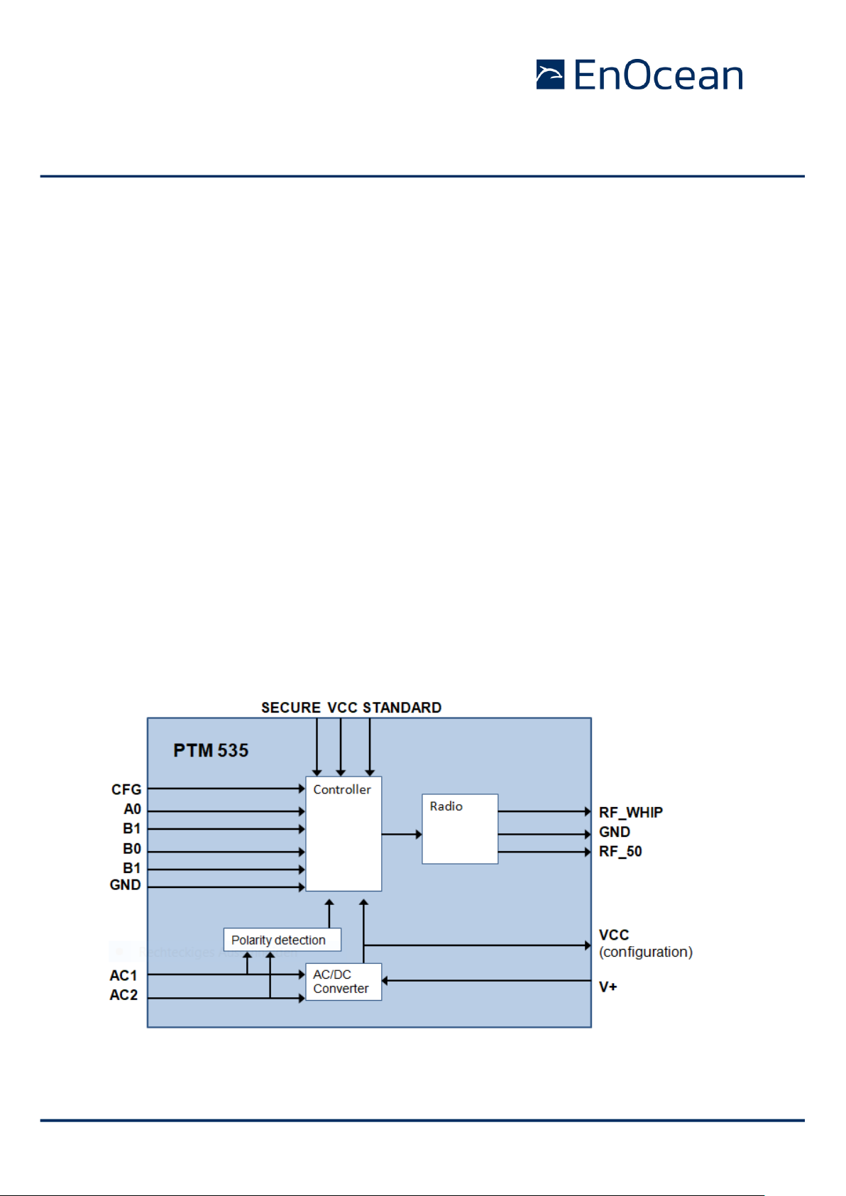
2.2 Block diagram
Figure 2 below shows the block diagram of PTM 535.
Figure 2 – PTM 535 functional block diagram
Page 10
USER MANUAL
PTM 535 / PTM 535U / PTM 535J – ENOCEAN TRANSMITTER MODULE
© 2019 EnOcean | www.enocean.com F-710-017, V1.0 PTM 535 / 535J User Manual | v1.5 | September 2020 | Page 10/36
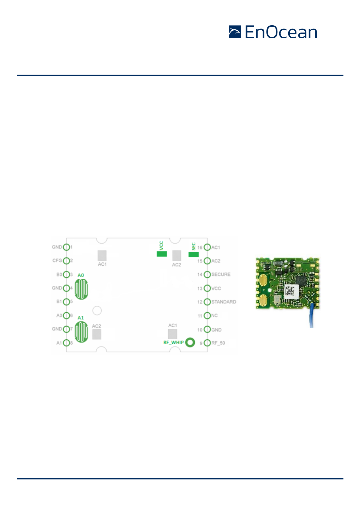
2.3 Interface pin layout
Figure 3 below shows the pin out and external interfaces of PTM 535 as seen from the top
(component side). Items marked in green are on the component side while items in grey
are on the bottom side.
In addition to the 16 boundary contacts, PTM 535 provides the following contact points:
◼ Meander contact A0
◼ Meander contact A1
◼ Connection for whip antenna RF_WHIP
◼ Footprint for LEARN button (connecting VCC and SEC)
◼ AC1 / AC2 power supply connection to ECO 200 harvester
(two contact pairs at the PCB bottom side to support different ECO 200 orientation)
Figure 3 – PTM 535 pin-out and external interfaces
Page 11

USER MANUAL
PTM 535 / PTM 535U / PTM 535J – ENOCEAN TRANSMITTER MODULE
© 2019 EnOcean | www.enocean.com F-710-017, V1.0 PTM 535 / 535J User Manual | v1.5 | September 2020 | Page 11/36
2.4 Interface pin functionality
Table 1 below describes the PTM 535 interface pin functionality.
Pin
Function
Characteristics
GND
Ground connection
Must be connected to GND
VCC_MODE
Internal Operating
voltage with 1k
Connect externally to SECURE or STANDARD pin to
change operation mode.
Also connected to LEARN button pad.
SECURE
Mode change pin
Connect this pin to VCC_MODE and press the ECO 200
harvester to change operation mode to enhanced security. Then disconnect.
Also connected to LEARN button footprint.
STANDARD
Mode change pin
Connect this pin to VCC_MODE and press the ECO 200
harvester to change operation mode to standard.
Then disconnect.
B0
O-Button Rocker B
Digital input, leave open or connect to GND
Internal pull-up
B1
I-Button Rocker B
Digital input, leave open or connect to GND
Internal pull-up
A0
O-Button Rocker A
Digital input, leave open or connect to GND
Internal pull-up, Connected to meander contact
A1
I-Button Rocker A
Digital input, leave open or connect to GND
Internal pull-up, Connected to meander contact
AC1
ECO 200 Input 1
ECO 200 or equivalent energy pulse
AC2
ECO 200 Input 2
ECO 200 or equivalent energy pulse
RF_WHIP
RF output
Output for whip antenna
RF_50
RF output
50 Ohm output for external antenna
CFG
Test pin
Do not connect
Table 1 – PTM 535 interface pin functionality
Page 12

USER MANUAL
PTM 535 / PTM 535U / PTM 535J – ENOCEAN TRANSMITTER MODULE
© 2019 EnOcean | www.enocean.com F-710-017, V1.0 PTM 535 / 535J User Manual | v1.5 | September 2020 | Page 12/36
3 Radio telegram format
3.1 Standard mode
In standard configuration, PTM 535 transmits the same telegram type as the PTM 210
pushbutton module. The telegram information is encoded within a 7 byte RPS telegram as
shown in Figure 4 below.
Figure 4 – PTM 535 telegram format
This telegram format uses the following fields:
◼ Telegram type (RORG, 1 byte)
The telegram type is always 0xF6 indicating an RPS telegram
◼ Switch data (DATA, 1 byte)
This field encodes the buttons that have been pressed. The encoding depends on the
number of buttons that have been pressed.
◼ EnOcean Unique Radio IO (EURID, 4 byte)
This field contains the ID which uniquely identifies each EnOcean products
◼ Switch status (STATUS)
This field encodes certain properties of the telegram as shown in below.
The STATUS field identifies the message type (U-Message or N-Message) as well as the
repeater level (original telegram, 1 hop repeated, 2 hop repeated) as shown in Figure 5
below.
Figure 5 – STATUS field encoding
Page 13

USER MANUAL
PTM 535 / PTM 535U / PTM 535J – ENOCEAN TRANSMITTER MODULE
© 2019 EnOcean | www.enocean.com F-710-017, V1.0 PTM 535 / 535J User Manual | v1.5 | September 2020 | Page 13/36
If one or two buttons are pressed, then the button status is transmitted using a so-called
N-Message. The DATA field format of such N-Message is shown in Figure 6 below.
Figure 6 – DATA field encoding for N-Messages (one or two button presses)
If either no button is pressed (only the ECO 200 is actuated), three buttons are pressed or
four buttons are pressed then the button status is transmitted using a so-called U-Message.
The DATA field format of such N-Message is shown in Figure 7 below.
Figure 7 – DATA field format for U-Messages (no, three or four button pressed)
Page 14

USER MANUAL
PTM 535 / PTM 535U / PTM 535J – ENOCEAN TRANSMITTER MODULE
© 2019 EnOcean | www.enocean.com F-710-017, V1.0 PTM 535 / 535J User Manual | v1.5 | September 2020 | Page 14/36
3.2 Enhanced security mode
While operating in enhanced security mode, PTM 535 sends secure telegrams in accordance
to EEP D2-03-00 as specified in EnOcean Equipment Profiles. For more details refer
to http://www.enocean-alliance.org/eep/.
These telegrams include a rolling code based on an incrementing counter which guarantees
that identical message content will be encrypted differently for each telegram thus preventing replay attacks.
The initial counter value is transmitted from PTM 535 to the receiver as part of the teach-in
telegram when entering secure mode. Subsequent secure telegrams do not specify this
counter value; therefore sender and receiver have to automatically increment their respective counters for each secure telegram to keep them synchronized.
When telegrams are not received by the receiver this may lead to a de-synchronization of
transmitter and receiver counters, i.e. the transmitter counter will have a greater value
than the receiver counter.
In order to prevent failure, the receiver will usually test the received rolling code against a
defined window of future expected rolling codes and – if successful - resynchronize its
counter automatically. The size of this rolling code window is defined on the receiver side.
It is important that the amount of consecutive, non-received telegrams does not exceed the
side of this window.
For more details please refer to http://www.enocean.com/en/security-specification/.
The rolling code is not transmitted with every telegram. It is only transmitted during teach-in. Afterwards the receiver has to increase the counter autonomously for
each received message.
It is strongly recommended to use PTM 535 in secure mode only in fixed installations with safe radio distance to avoid de-synchronization of sender and receiver.
De-synchronization will occur if PTM 535 is operated outside the range of the receiver consecutively more often than the size of the rolling code window defined
on the receiver.
The same may apply if consecutive telegrams are lost on the receiver side due to
power interruptions.
In these cases it is necessary to set the receiver in LRN mode and teach-in the
device again.
Page 15

USER MANUAL
PTM 535 / PTM 535U / PTM 535J – ENOCEAN TRANSMITTER MODULE
© 2019 EnOcean | www.enocean.com F-710-017, V1.0 PTM 535 / 535J User Manual | v1.5 | September 2020 | Page 15/36
3.3 Switching between operation modes
PTM 535 can be switched from standard mode (default) to enhanced security mode by connecting SECURE with VCC_MODE (see chapter 3 for details) and triggering the ECO 200.
Upon entry into enhanced security mode, a teach-in telegram is sent by PTM 535. The type
of the teach-in telegram (Teach_In_Info : Type) is: 1-PTM.
PTM 535 will continue to transmit secure teach-in telegrams until the SECURE pin is disconnected from the VCC_MODE pin.
The secure teach-in message has to be transmitted as two consecutive telegrams due to its
payload size. Therefore, the ECO generator has to be triggered twice in order to transmit a
complete secure teach-in message. It is not required that the two contacts (SECURE and
VCC_MODE) remain connected throughout the transmission of both messages. It is sufficient to connect them while actuating the ECO energy generator the first time.
For more information on the structure of the teach-in telegram please refer to chapter 4.2
of http://www.enocean.com/en/security-specification/.
PTM 535 can be switched from secure mode to normal mode by connecting STANDARD with
VCC_MODE and triggering the ECO 200. Then disconnect the pins.
Before changing the operating mode please make sure to clear the device from all
receivers which have been taught to work with this device before. Otherwise the
receiver will ignore the telegrams and the application will not work.
3.4 Transmission timing
The setup of the transmission timing allows avoiding possible collisions with data packages
of other EnOcean transmitters as well as disturbances from the environment. With each
transmission cycle, 3 identical subtelegrams are transmitted within 40 ms.
The transmission of a subtelegram lasts approximately 0.7 ms. The delay between the
three transmission bursts is affected at random.
PTM 535 transmits in secured mode 2 identical subtelegrams with length of ~ 1.3 ms
PTM radio modules are designed for manual button operation. The actuation rate
should therefore be limited to no more than 5 actuations per second.
For higher actuation rates, PTM radio modules might temporarily stop operation
and will restart operation after a period of 2 seconds without operation.
Page 16

USER MANUAL
PTM 535 / PTM 535U / PTM 535J – ENOCEAN TRANSMITTER MODULE
© 2019 EnOcean | www.enocean.com F-710-017, V1.0 PTM 535 / 535J User Manual | v1.5 | September 2020 | Page 16/36
4 PTM 535 configuration
PTM 535 provides a configuration interface that can be used to configure certain device
parameters.
4.1 PTM 535 configuration parameters
The following parameters can be configured for PTM 535 (868.300 MHz):
◼ Content of the radio telegrams
This can be configured for each of the 32 possible input combination (A0, A1, B0,
B1, direction of ECO movement)
◼ Default operation mode
This can be standard (default) or enhanced security. Changing the mode is still possible using the HW mechanism described in chapter 3.3
◼ Secure teach-in telegram transmission
The secure teach-in telegram transmission can start only when the ECO 200 is
pressed, only when the ECO 200 is released or at any ECO 200 action (press or release)
◼ Number of secure subtelegrams
If PTM 535 is powered by an ECO 200 harvester and operating in enhanced security
mode then it will always transmit 2 subtelegrams.
If PTM 535 is powered by another energy source such as a battery and operating in
enhanced security mode, then it can be selected if it should transmit 2 or 3 subtelegrams.
Note that configuration is currently only supported for PTM 535 (868.300 MHz).
Configuration of PTM 535U (902.875 MHz) and PTM 535J (928.350 MHz) is currently not supported.
Page 17

USER MANUAL
PTM 535 / PTM 535U / PTM 535J – ENOCEAN TRANSMITTER MODULE
© 2019 EnOcean | www.enocean.com F-710-017, V1.0 PTM 535 / 535J User Manual | v1.5 | September 2020 | Page 17/36
4.2 PTM 535 configuration interface
The PTM 535 configuration interface consists of test points MP1- MP6. The function of these
test points is summarized in Table 2 below.
Table 2 – PTM 535 configuration interface
4.3 PTM 535 test point location
Figure 8 below shows the location of the test points MP1 … MP6. For the exact location
refer to the product drawing in chapter 1.6.
Figure 8 – PTM 535 test point location
Pad
Signal
Name
Characteristics
Segger
J-Link Signal
Segger
J-Link Pin
MP1
VCC
Configuration interface
(Supply voltage)
VTref
1
MP2
GND
Configuration interface
(Ground)
GND
4/6/8/10
/12
MP3
TDIO
Configuration interface
(Data)
TMS
7
MP4
TCK
Configuration interface
(Clock)
TCK
9
MP5
V+
Power supply (from Segger)
5V-Supply
19
MP6
RESET
Optional
RESET
15
Page 18

USER MANUAL
PTM 535 / PTM 535U / PTM 535J – ENOCEAN TRANSMITTER MODULE
© 2019 EnOcean | www.enocean.com F-710-017, V1.0 PTM 535 / 535J User Manual | v1.5 | September 2020 | Page 18/36
4.4 Connection between Segger J-Link and PTM 535
PTM 535 has to be connected to the Segger J-Link connector for configuration. Figure 9
below shows the pin-out of the Segger J-Link connector.
Figure 9 – Segger J-Link connector pin-out
Two approaches can be used to connect Segger J-Link and PTM 535 depending on the power supply of PTM 535 during configuration. Both approaches are described below.
4.4.1 Segger power supply (6-Pin interface)
Supplying power by Segger J-Link to PTM 535 is the recommended approach. It requires a
6 pin test interface.
In this case, power is supplied by Segger J-Link to PTM 535 via PTM 535 MP5 (V+) connected to Segger Pin 19. The “5V Target Power Supply” option has to be activated at the
Segger user interface. We recommend checking available voltage supply.
The required connections are shown in Figure 10 below.
Figure 10 – 6-Pin configuration interface (Power supplied by Segger)
Page 19

USER MANUAL
PTM 535 / PTM 535U / PTM 535J – ENOCEAN TRANSMITTER MODULE
© 2019 EnOcean | www.enocean.com F-710-017, V1.0 PTM 535 / 535J User Manual | v1.5 | September 2020 | Page 19/36
4.4.2 External power supply (4 pin configuration interface)
This approach allows you to use a 4 needle test adapter instead of a 6 needle adapter.
Existing 4 needle adapters built for PTM 335 can be reused.
It requires to supply PTM 535 by an external power supply (2.0 - 3.3 V) connected to PTM
535 MP1 and to Segger VTref (IO voltage reference). The external power supply ground has
to be connected to PTM 535 MP2 (GND) and Segger GND.
The required connections are shown in Figure 11 below.
Figure 11 – 4-Pin configuration interface (external power supply)
Page 20

USER MANUAL
PTM 535 / PTM 535U / PTM 535J – ENOCEAN TRANSMITTER MODULE
© 2019 EnOcean | www.enocean.com F-710-017, V1.0 PTM 535 / 535J User Manual | v1.5 | September 2020 | Page 20/36
4.5 Required tools
The following tools are required to configure PTM 535:
◼ Needle adapter
Suitable adapter to contact test points as described in the previous chapter.
EnOcean can provide a mechanical design example upon request.
◼ Debugger / Programmer
J-Link Plus or higher from Segger is required, see:
https://www.segger.com/products/debug-probes/j-link/models/j-link-plus/
◼ J-Link Software and Documentation Pack
https://www.segger.com/downloads/jlink/#J-LinkSoftwareAndDocumentationPack
◼ PTM 535 Configuration Suite
http://www.enocean.com/en/download/
Please check PTM 535 Config help for a detailed description of the program usage.
PTM 535 Configurator uses Segger tools to communicate with the radio chip. If a
window pops up “to unlock” the device you must select NO (details see PTM 535
Config help). Due to radio approval requirements a wrong configuration will lead
the module to stop radio transmission.
Radio module configuration is only possible with the EnOcean PTM 535 Configurator tool. Follow exactly the below written sequence to chance PTM 535 configuration. Due to radio approval requirements, a wrong configuration will lead the
module to stop radio transmission.
Additional care has to be taken to configure correct values for DATA and STATUS
fields. Otherwise PTM 535 might not work properly together with repeaters or
receivers.
Page 21

USER MANUAL
PTM 535 / PTM 535U / PTM 535J – ENOCEAN TRANSMITTER MODULE
© 2019 EnOcean | www.enocean.com F-710-017, V1.0 PTM 535 / 535J User Manual | v1.5 | September 2020 | Page 21/36
4.6 Configuration setup
Figure 12 below shows the setup required to configure PTM 535.
Figure 12 – Setup for PTM 535 configuration
4.7 User Interface
Figure 13 below shows the user interface of the PTM 535 Configurator.
Figure 13 – User interface of PTM 535 Configurator
USB
PTM 535 Config + Segger SW
PTM 535
Segger J-Link Plus
Adapter
Page 22

USER MANUAL
PTM 535 / PTM 535U / PTM 535J – ENOCEAN TRANSMITTER MODULE
© 2019 EnOcean | www.enocean.com F-710-017, V1.0 PTM 535 / 535J User Manual | v1.5 | September 2020 | Page 22/36
4.8 Execution sequence
The following steps have to be executed exactly in the below given order:
1. “Get the device info” (show device info)
2. “Read PTM 535” the current configuration (show config and do a backup)
3. Modify the configuration fields (security key, telegram data, etc.)
4. “Write to PTM 535” the modified configuration
Quit Segger info window with no (details see PTM Config help)!
5. Save configuration to file (if you want to configure additional PTM 535)
6. Load configuration from file
7. “Write to PTM 535” the modified configuration to additional module
Quit Segger info window with no (details see PTM Config help)!
PTM 535 Configurator uses Segger tools to communicate with the radio chip. If a
window pops up “to unlock” the device, you must select NO (for details, see
PTM 535 Config help). Due to radio approval requirements, trying to unlock the
device will cause the module to stop radio transmission.
Radio module configuration is only possible with the EnOcean PTM 535 Configurator tool. Follow exactly the above written sequence to chance PTM 535 configuration. Due to radio approval requirements, trying to use an incorrect configuration will lead the module to stop radio transmission.
Additional care has to be taken to configure correct values for DATA and STATUS
fields. Otherwise PTM 535 might not work properly together with repeaters or
receivers.
Page 23

USER MANUAL
PTM 535 / PTM 535U / PTM 535J – ENOCEAN TRANSMITTER MODULE
© 2019 EnOcean | www.enocean.com F-710-017, V1.0 PTM 535 / 535J User Manual | v1.5 | September 2020 | Page 23/36
5 Application information
5.1 Connection to ECO 200 energy harvester
PTM 535 can be connected to ECO 200 without soldering.
ECO 200 provides contact springs which can directly be
connected to the corresponding contact pads of PTM 535.
The contact pads on the bottom of the PCB are shown below
(left). A second orientation where PTM 535 is rotated 180° with
respect to ECO 200 is also possible as shown with dashed lines.
5.2 How to populate a teach-in button (for enhanced security mode)
PTM 535 provides two landing pads for a LRN button called SECURE and VCC_MODE. If a
pushbutton is mounted then this will act as secure teach-in button. By pressing the button
and triggering the ECO 200, the secure teach-in process is triggered, the module switches
to secure mode and transmits a secure teach-in telegram.
To switch operation back to standard mode, the STANDARD and VCC_MODE pin must be
connected. There is no push button option available for this step.
A drilling is positioned between the pads. This enables the possibility to mount also push
buttons which have pressing point deeper than the PCB (better tactile handling) or are operated from the bottom.
Please see drawings of PTM 535 for detailed information and position of pads. The design of
the pads was optimized for Compact High-speed Mounting Type (Surface Mount) SKQY Series switch from ALPS.
Figure 14 – LEARN button example for PTM 535
(1)
1
Picture Source:
https://www.alps.com/prod/info/E/HTML/Tact/SurfaceMount/SKQY/SKQY_list.html
Page 24

USER MANUAL
PTM 535 / PTM 535U / PTM 535J – ENOCEAN TRANSMITTER MODULE
© 2019 EnOcean | www.enocean.com F-710-017, V1.0 PTM 535 / 535J User Manual | v1.5 | September 2020 | Page 24/36
5.3 Antenna specification
PTM 535 provides two antenna options:
◼ 86 mm whip (wire) antenna (PTM 535 only), connected to RF_WHIP
This is populated by default, see Figure 15 for the mechanical dimensions
◼ 64 mm whip (wire) antenna (PTM 535U and PTM 535J only), connected to RF_WHIP
This is populated by default, see Figure 15 for the mechanical dimensions
◼ 50 Ω antenna connected to RF_50
If this shall be used then the whip antenna has to be removed. Only the approved
antenna shown below may be used.
Figure 15 – Whip antenna specification
PTM 535: L=86 mm, PTM 535U / PTM 535J: L = 64 mm
Page 25

USER MANUAL
PTM 535 / PTM 535U / PTM 535J – ENOCEAN TRANSMITTER MODULE
© 2019 EnOcean | www.enocean.com F-710-017, V1.0 PTM 535 / 535J User Manual | v1.5 | September 2020 | Page 25/36
5.4 Layout recommendations
PTM 535 can be soldered onto a host PCB. Figure 16 below shows the required footprint
shape. EnOcean can provides Gerber data if required.
Figure 16 – PCB footprint for PTM 535
Figure 17 below shows the required keep out area on a host PCB form PTM 535. No copper
surface area is allowed within this area.
Figure 17 – Keep out area on host PCB for PTM 535
PTM 535
Antenna
Page 26

USER MANUAL
PTM 535 / PTM 535U / PTM 535J – ENOCEAN TRANSMITTER MODULE
© 2019 EnOcean | www.enocean.com F-710-017, V1.0 PTM 535 / 535J User Manual | v1.5 | September 2020 | Page 26/36
5.5 Transmission range
The main factors that influence the system transmission range are type and location of the
antennas of the receiver and the transmitter, type of terrain and degree of obstruction of
the link path, sources of interference affecting the receiver, and “Dead” spots caused by
signal reflections from nearby conductive objects.
Since the expected transmission range strongly depends on this system conditions, range
tests should categorically be performed before notification of a particular range that will be
attainable by a certain application.
The following figures for expected transmission range are considered by using a PTM 535
radio transmitter device and a TCM 310 / TCM 310U / TCM 410J radio receiver device with
installed whip antenna and may be used as a rough guide only:
◼ Line-of-sight connections: Typically 30 m range in corridors, up to 100 m in halls
◼ Plasterboard walls / dry wood: Typically 30 m range, through max. 5 walls
◼ Line-of-sight connections: Typically 30 m range in corridors, up to 100 m in halls
◼ Ferroconcrete walls / ceilings: Typically 10 m range, through max. 1 ceiling
◼ Fire-safety walls, elevator shafts, staircases and supply areas should be considered
as screening.
The angle at which the transmitted signal hits the wall is very important. The effective wall
thickness – and with it the signal attenuation – varies according to this angle. Signals
should be transmitted as directly as possible through the wall. Wall niches should be avoided.
Other factors restricting transmission range include:
◼ Switch mounted on metal surfaces (up to 30% loss of transmission range)
◼ Hollow lightweight walls filled with insulating wool on metal foil
◼ False ceilings with panels of metal or carbon fiber
◼ Lead glass or glass with metal coating, steel furniture
The distance between EnOcean receivers and other transmitting devices such as computers, audio and video equipment that also emit high-frequency signals should be at least
0.5 m
A summarized application note to determine the transmission range within buildings is
available as download from www.enocean.com.
Page 27

USER MANUAL
PTM 535 / PTM 535U / PTM 535J – ENOCEAN TRANSMITTER MODULE
© 2019 EnOcean | www.enocean.com F-710-017, V1.0 PTM 535 / 535J User Manual | v1.5 | September 2020 | Page 27/36
6 Regulatory information
PTM 535 has been tested according to standards for RED (European Union), FCC (United
States), ISED (Canada) and ARIB (Japan) certification.
6.1 RED (European Union)
The Radio Equipment Directive (2014/53/EU, typically referred to as RED) replaces the old
R&TTE directive from 1999 as regulatory framework for radio products in the European Union. All products sold to final customers after 12th of June, 2017 have to be compliant to
RED.
At the time of writing, the text of the RED legislation was available from this link:
http://eur-lex.europa.eu/eli/dir/2014/53/oj
Dolphin radio modules such as PTM 535 are components which are delivered to OEM manufacturers for their use in final or combined products.
It is the responsibility of the OEM manufacturer to demonstrate compliance to all applicable
EU directives and standards. The attestation of conformity for PTM 535 serves as input to
the declaration of conformity for the full product.
At the time of writing, guidance on the implementation of EU product rules – the so called
“Blue Guide” – was available from this link:
http://ec.europa.eu/DocsRoom/documents/18027/
Specifically within the new RED framework, all OEM manufacturers have for instance to
fulfill the following additional requirements:
◼ Provide product branding (on the product) clearly identifying company name or
brand and product name as well as type, charge or serial number for market surveillance
◼ Include (with the product) documentation containing full postal address of the man-
ufacturer as well as radio frequency band and max. transmitting power
◼ Include (with the product) user manual, safety information and a declaration of con-
formity for the final product in local language
◼ Provide product development and test documentation upon request
Please contact an accredited test house for detailed guidance.
The maximum transmitting power of PTM 535 using a whip antenna is +5 dBm.
Page 28

USER MANUAL
PTM 535 / PTM 535U / PTM 535J – ENOCEAN TRANSMITTER MODULE
© 2019 EnOcean | www.enocean.com F-710-017, V1.0 PTM 535 / 535J User Manual | v1.5 | September 2020 | Page 28/36
6.2 FCC (United States)
6.2.1 FCC grant of equipment authorization
Page 29

USER MANUAL
PTM 535 / PTM 535U / PTM 535J – ENOCEAN TRANSMITTER MODULE
© 2019 EnOcean | www.enocean.com F-710-017, V1.0 PTM 535 / 535J User Manual | v1.5 | September 2020 | Page 29/36
6.2.2 FCC regulatory statement
This device complies with Part 15 of the FCC rules. Operation is subject to the following two
conditions:
1. This device may not cause harmful interference, and
2. This device must accept any interference received, including interference that may
cause undesired operation.
To comply with FCC/IC RF exposure limits for general population / uncontrolled exposure,
the antenna(s) used for this transmitter must be installed to provide a separation distance
of at least 20 cm from all persons and must not be co-located or operating in conjunction
with any other antenna or transmitter
Warning
Changes or modifications not expressly approved by the party responsible for compliance
could void the user’s authority to operate the equipment.
Interference
This equipment has been tested and found to comply with the limits for a Class B digital
device, pursuant to Part 15 of the FCC Rules. These limits are designed to provide reasonable protection against harmful interference in a residential installation.
This equipment generates uses and can radiate radio frequency energy and, if not installed
and used in accordance with the instructions, may cause harmful interference to radio
communications. However, there is no guarantee that interference will not occur in a particular installation.
If this equipment does cause harmful interference to radio or television reception, which
can be determined by turning the equipment off and on, the user is encouraged to try to
correct the interference by one of the following measures:
◼ Reorient or relocate the receiving antenna.
◼ Increase the separation between the equipment and receiver.
◼ Connect the equipment into an outlet on a circuit different from that to which the
receiver is connected.
◼ Consult the dealer or an experienced radio/TV technician for help.
Page 30

USER MANUAL
PTM 535 / PTM 535U / PTM 535J – ENOCEAN TRANSMITTER MODULE
© 2019 EnOcean | www.enocean.com F-710-017, V1.0 PTM 535 / 535J User Manual | v1.5 | September 2020 | Page 30/36
6.3 ISED (Canada)
6.3.1 ISED technical acceptance certificate
Page 31

USER MANUAL
PTM 535 / PTM 535U / PTM 535J – ENOCEAN TRANSMITTER MODULE
© 2019 EnOcean | www.enocean.com F-710-017, V1.0 PTM 535 / 535J User Manual | v1.5 | September 2020 | Page 31/36
Page 32

USER MANUAL
PTM 535 / PTM 535U / PTM 535J – ENOCEAN TRANSMITTER MODULE
© 2019 EnOcean | www.enocean.com F-710-017, V1.0 PTM 535 / 535J User Manual | v1.5 | September 2020 | Page 32/36
6.3.2 ISED regulatory statement
6.3.2.1 English version
This radio transmitter has been approved by Industry Canada to operate with the antenna
types listed with the maximum permissible gain indicated. Antenna types not included in
this list, having a gain greater than the maximum gain indicated for that type, are strictly
prohibited for use with this device.
This device complies with Industry Canada license-exempt RSS standard(s). Operation is
subject to the following two conditions:
1. This device may not cause interference, and
2. This device must accept any interference, including interference that may cause un-
desired operation of the device.
This equipment has been tested and found to comply with the limits for a Class B digital
device, pursuant to ICES-003. These limits are designed to provide reasonable protection
against harmful interference in a residential installation.
This equipment generates uses and can radiate radio frequency energy and, if not installed
and used in accordance with the instructions, may cause harmful interference to radio
communications. However, there is no guarantee that interference will not occur in a particular installation.
If this equipment does cause harmful interference to radio or television reception, which
can be determined by turning the equipment off and on, the user is encouraged to try to
correct the interference by one of the following measures:
◼ Reorient or relocate the receiving antenna.
◼ Increase the separation between the equipment and receiver.
◼ Connect the equipment into an outlet on a circuit different from that to which the
receiver is connected.
◼ Consult the dealer or an experienced radio/TV technician for help
Page 33

USER MANUAL
PTM 535 / PTM 535U / PTM 535J – ENOCEAN TRANSMITTER MODULE
© 2019 EnOcean | www.enocean.com F-710-017, V1.0 PTM 535 / 535J User Manual | v1.5 | September 2020 | Page 33/36
6.3.2.2 French version
PRUDENCE: Changements ou modifications pourraient annuler le droit de l'utilisateur à utiliser l'équipement non autorisées.
Conformément à la réglementation d'Industrie Canada, le présent émetteur radio peut
fonctionner avec une antenne d'un type et d'un gain maximal (ou inférieur) approuvé pour
l'émetteur par Industrie Canada. Dans le but de réduire les risques de brouillage radioélectrique à l'intention des autres utilisateurs, il faut choisir le type d'antenne et son gain de
sorte que la puissance isotrope rayonnée équivalente (p.i.r.e.) ne dépasse pas l'intensité
nécessaire à l'établissement d'une communication satisfaisante.
Le présent appareil est conforme aux CNR d’Industrie Canada applicables aux appareils
radio exempts de licence. L’exploitation est autorisée aux deux conditions suivantes:
1. L’appareil ne doit pas produire de brouillage, et
2. L’utilisateur de l’appareil doit accepter tout brouillage radioélectrique subi, même si
le brouillage est susceptible d’en compromettre le fonctionnement.
Ces limites sont conçues pour fournir une protection raisonnable contre les interférences
nuisibles dans une installation résidentielle. Cet équipement génère, utilise et peut émettre
une énergie de radiofréquence et, s'il n'est pas installé et utilisé conformément a ux instructions, il peut causer des interférences nuisibles aux communications radio. Cependant,
il n'existe aucune garantie que des interférences no se produiront pas dans une installation
particulière.
Si cet équipement provoque des interférences nuisibles à la réception radio ou télévision, ce
qui peut être déterminé en mettant l'équipement hors et sous tension, l'utilisateur est encouragé à essayer de corriger l'interférence par une ou plusieurs des mesures suivantes:
◼ Réorienter ou déplacer l'antenne de réception.
◼ Augmentez la distance entre l'équipement et le récepteur.
◼ Connecter l'équipement à une sortie sur un circuit différent de celui sur lequel le ré-
cepteur est branché.
◼ Consulter le revendeur ou un technicien radio / télévision expérimenté pour de l'aide
Page 34

USER MANUAL
PTM 535 / PTM 535U / PTM 535J – ENOCEAN TRANSMITTER MODULE
© 2019 EnOcean | www.enocean.com F-710-017, V1.0 PTM 535 / 535J User Manual | v1.5 | September 2020 | Page 34/36
6.4 ARIB (Japan)
6.4.1 ARIB (Japan) certificate
Page 35

USER MANUAL
PTM 535 / PTM 535U / PTM 535J – ENOCEAN TRANSMITTER MODULE
© 2019 EnOcean | www.enocean.com F-710-017, V1.0 PTM 535 / 535J User Manual | v1.5 | September 2020 | Page 35/36
6.4.2 ARIB (Japan) regulatory requirements
PTM 535J has been designed and tested to fulfil the approval requirements for ARIB STDT108 based on the built-in firmware.
When products using PTM 535 are placed on the Japanese market, they must carry the
Specified Radio Equipment marking.
PTM 535J will be laser marked on the bottom side of the PCB with the content shown in
Table 3 below.
Field
Content
Description
1
MODEL: PTM 535J xy
A535–z dc
Step Code „xy“ (z.B. CA)
State Code „-z“ (z.B. -1);
Date Code “dc” (z.B. 42/17)
2
003-180056
ARIB ID with sign
3
DMC
Data Matrix Code
Table 3 – PTM 535J product marking
Page 36

USER MANUAL
PTM 535 / PTM 535U / PTM 535J – ENOCEAN TRANSMITTER MODULE
© 2019 EnOcean | www.enocean.com F-710-017, V1.0 PTM 535 / 535J User Manual | v1.5 | September 2020 | Page 36/36
7 Product history
Table 4 below outlines the product history of PTM 535 and indicates key changes made between different revisions.
Revision
Introduction
Key features / changes
PTM 535 CA-02
Nov 2017
Prototypes for lead customer evaluation
PTM 535 DA-03
May 2018
First product release (868.300 MHz version)
PTM 535 DB-06
Aug 2019
Support for use of Base ID
PTM 535 DB-07
Jan 2020
HW optimization (alternative components)
PTM 535J DA-02
Feb 2020
First product release (928.350 MHz version)
PTM 535U DA-02
Oct 2020
First product release (902.875 MHz version)
Table 4 – PTM 535 product history
 Loading...