

Page 1

© 2020 EnOcean | www.enocean.com PTM 210 / PTM 215 / PTM 215U / PTM 215J / User Manual Page 1/48
USER MANUAL
PTM 210 / PTM 215 / PTM 215U / PTM 215J
DC Step code and later
PTM 210 / PTM 215
PTM 215U
PTM 215J
Pushbutton transmitter modules
DC Step code and later
The product is protected by the following granted Patents:
US7710227, DE10315765B4
US9614553, EP1312171B1, CN100508406C
EP1389358B1, JP4225792B2
US7019241, EP1550202B1, DE50303733D1, CN1689218B
US7391135, EP1611663B1, DE10315764B4,
US8502470, JP5617103B2
EP2524572B1
And also by pending or not yet published Patents and Designs.
Page 2

© 2020 EnOcean | www.enocean.com PTM 210 / PTM 215 / PTM 215U / PTM 215J User Manual November 2020 | Page 2/48
USER MANUAL
PTM 210 / PTM 215 / PTM 215U / PTM 215J
DC Step code and later
REVISION HISTORY
The following major modifications and improvements have been made from the first version
of this document:
No
Major Changes
2.0
Update to modules with step code DC.
2.1
Update of certification numbers in US and Japan.
2.2
Update of certificate and product releases chapter.
2.3
Extended mode change description, added product safety recommendations for
final product. Small corrections.
Published by EnOcean GmbH, Kolpingring 18a, 82041 Oberhaching, Germany
www.enocean.com, info@enocean.com, phone ++49 (89) 6734 6890
© EnOcean GmbH
All Rights Reserved
Important!
This information describes the type of component and shall not be considered as assured
characteristics. No responsibility is assumed for possible omissions or inaccuracies. Circuitry
and specifications are subject to change without notice. For the latest product specifications,
refer to the EnOcean website: http://www.enocean.com.
As far as patents or other rights of third parties are concerned, liability is only assumed for
devices, not for the described applications, processes and circuits.
EnOcean does not assume responsibility for use of devices described and limits its liability to
the replacement of devices determined to be defective due to workmanship. Devices or systems containing RF components must meet the essential requirements of the local legal authorities.
The devices must not be used in any relation with equipment that supports, directly or indirectly, human health or life or with applications that can result in danger for people, animals
or real value.
Components of the devices are considered and should be disposed of as hazardous waste.
Local government regulations are to be observed.
Packing: Please use the recycling operators known to you. By agreement we will take packing
material back if it is sorted. You must bear the costs of transport. For packing material that
is returned to us unsorted or that we are not obliged to accept, we shall have to invoice you
for any costs incurred.
Page 3

© 2020 EnOcean | www.enocean.com PTM 210 / PTM 215 / PTM 215U / PTM 215J User Manual November 2020 | Page 3/48
USER MANUAL
PTM 210 / PTM 215 / PTM 215U / PTM 215J
DC Step code and later
TABLE OF CONTENT
1 GENERAL DESCRIPTION ............................................................... 5
1.1 Product variants and ordering codes ...................................................... 5
1.1.1 Previous / other product variants ....................................................................... 6
1.2 Basic Functionality ............................................................................. 6
1.3 Typical Applications ............................................................................ 8
1.4 Technical Data .................................................................................. 10
1.5 Mechanical Interface .......................................................................... 10
1.6 Environmental Conditions ................................................................... 11
1.7 References ....................................................................................... 11
2 FUNCTIONAL DESCRIPTION ........................................................ 12
2.1 Block Diagram .................................................................................. 12
2.2 Contact Nipples Assignment ................................................................ 13
2.3 Available EnOcean Equipment Profiles .................................................. 13
3 OPERATING MODES ................................................................... 15
3.1 Normal Mode Operation...................................................................... 15
3.2 Secure Mode Operation ...................................................................... 15
3.2.1 Implicit RLC – legacy, not recommended ........................................................... 17
3.2.2 Explicit RLC – recommended ........................................................................... 17
3.2.3 Security Teach-in ........................................................................................... 17
3.3 Switching between modes .................................................................. 18
3.4 Factory Reset ................................................................................... 20
4 RADIO COMMUNICATION ............................................................ 21
4.1 ERP 1 Communication ........................................................................ 21
4.1.1 ULP Frames ................................................................................................... 21
4.1.2 Common Frames ............................................................................................ 23
4.2 ERP 2 Communication ........................................................................ 24
4.2.1 Normal Mode Telegram ................................................................................... 24
4.2.2 Secure Mode Telegram ................................................................................... 24
4.3 Redundant transmission ..................................................................... 24
Page 4

© 2020 EnOcean | www.enocean.com PTM 210 / PTM 215 / PTM 215U / PTM 215J User Manual November 2020 | Page 4/48
USER MANUAL
PTM 210 / PTM 215 / PTM 215U / PTM 215J
DC Step code and later
5 CONFIGURATION VIA NFC – PTM 215 / PTM 215J / PTM 215U ......... 25
5.1 NFC Interface Overview...................................................................... 25
5.2 NFC Access Protection ........................................................................ 25
5.3 NFC Parameters – Memory Map ........................................................... 25
5.3.1 Device Identification NDEF .............................................................................. 27
5.3.2 User Information NDEF ................................................................................... 27
5.3.3 NFC Header ................................................................................................... 27
5.3.4 Configuration ................................................................................................. 29
5.4 NFC Interaction with the PTM Application .............................................. 33
5.5 NFC Interface Tools ........................................................................... 33
5.5.1 EnOcean Tool ................................................................................................ 33
5.5.2 EnOcean NFC Configurator .............................................................................. 35
5.5.3 Including NFC Functionality into Existing Customer Tools .................................... 35
6 APPLICATIONS INFORMATION ..................................................... 37
6.1 Product Label ................................................................................... 37
6.2 Content of QR codes .......................................................................... 39
6.3 Construction of application specific Switch Rockers ................................. 40
6.4 Device Mounting ............................................................................... 41
6.5 Transmission Range .......................................................................... 42
7 AGENCY APPROVALS .................................................................. 43
7.1 PTM 210 and PTM 215: Radio Approval for the European Market ............... 43
7.3 PTM 215U: FCC and Industry Canada Regulatory Statements ................... 44
7.4 PTM 215J: Japanese Type Approval ...................................................... 45
8 PRODUCT SAFETY INSTRUCTIONS ............................................... 46
9 PRODUCT RELEASES .................................................................. 47
Page 5
© 2020 EnOcean | www.enocean.com PTM 210 / PTM 215 / PTM 215U / PTM 215J User Manual November 2020 | Page 5/48
USER MANUAL
PTM 210 / PTM 215 / PTM 215U / PTM 215J
DC Step code and later
1 GENERAL DESCRIPTION
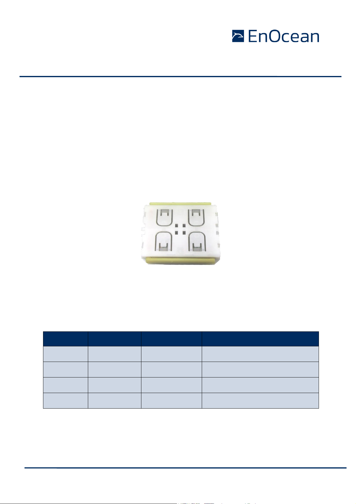
The pushbutton transmitter family PTM 21x from EnOcean enables the implementation of
wireless switches and remote controls without batteries. The PTM 21x pushbutton transmitters are self-powered (no batteries) and therefore maintenance-free. The power is provided
by a built-in electro-dynamic power generator.
The main application are wireless switches in smart buildings. Products based on PTM 21x
modules can also be used in hermetically sealed systems or in remote (not easily accessible)
locations.
PTM 21x devices are available in variants supporting the 868 MHz, 902 MHz and 928MHz
radio interface protocols of EnOcean Alliance Radio Standard ERP 1 & ERP 2.
Figure 1 Electro-dynamic powered pushbutton transmitter module PTM 21x
With the major product update to the step code DC an additional NFC interface was added
and the security mode option was extended to all PTM21x family members and frequencies.
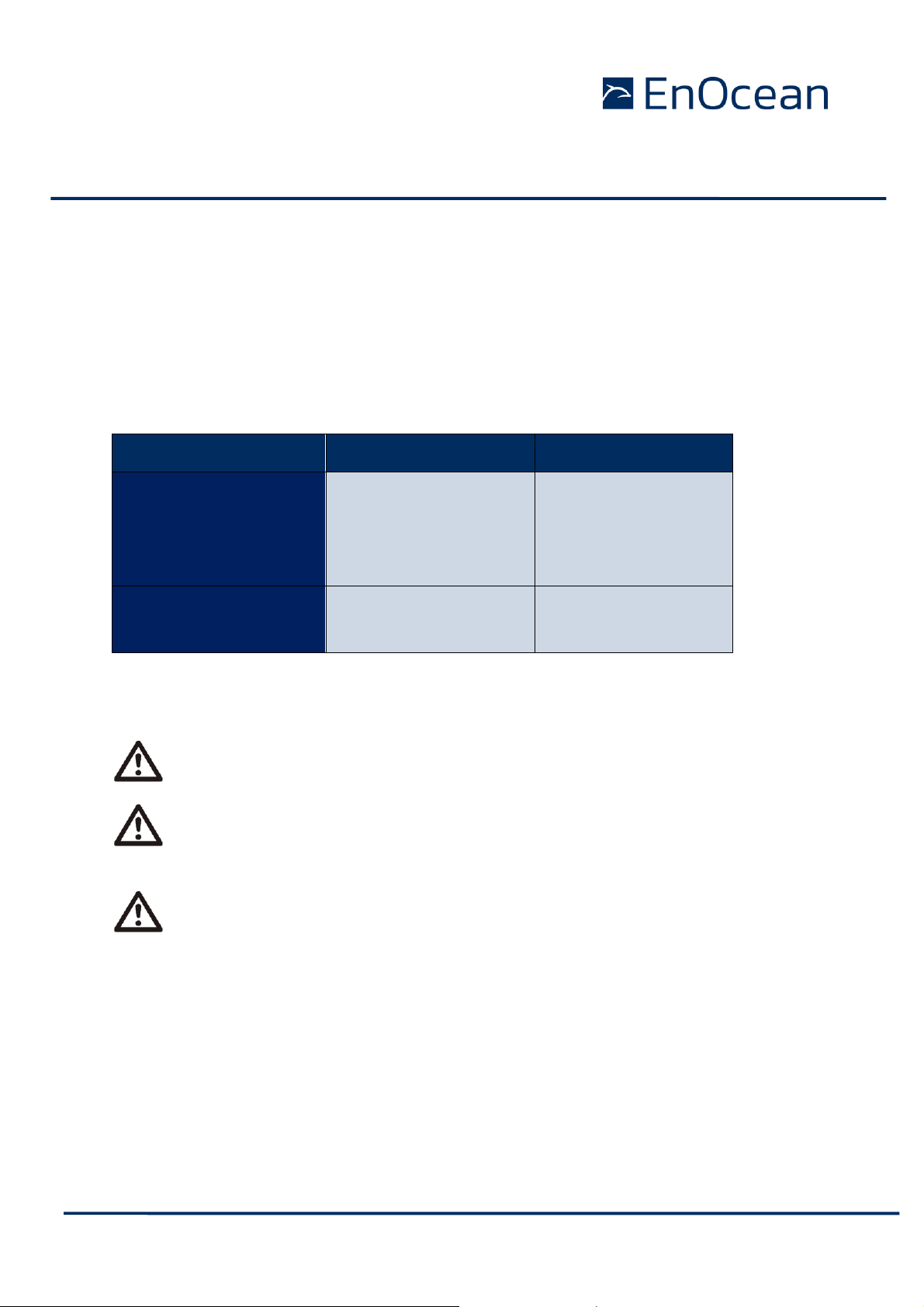
1.1 Product variants and ordering codes
The PTM 21x product family contains the following product variants with product revision DC:
Type
Frequency
Ordering Code
Product specifics
PTM 210
868.300 MHz
S3001-A210
Encryption capability
PTM 215
868.300 MHz
S3001-A215
Encryption capability & NFC Interface
PTM 215U
902.875 MHz
S3051-A215
Encryption capability & NFC Interface
PTM 215J
928.350 MHz
S3061-A215
Encryption capability & NFC Interface
Table 1 Product Variants
Page 6
© 2020 EnOcean | www.enocean.com PTM 210 / PTM 215 / PTM 215U / PTM 215J User Manual November 2020 | Page 6/48
USER MANUAL
PTM 210 / PTM 215 / PTM 215U / PTM 215J
DC Step code and later
1.1.1 Previous / other product variants
Previous versions of the PTM 21x product family (identified by step codes (DA and DB) contain
only a subset of the functionality described in the document. Should you need information
related to these products then please do not use this document as reference and refer to
EnOcean support (support@enocean.com) for more details.
This document describes PTM modules with the EnOcean Radio Standard. For other radio
standards PTMs (e.g. BLE, ZigBee) please visit the EnOcean Product page1 and select the
product type to find the available information.
1.2 Basic Functionality
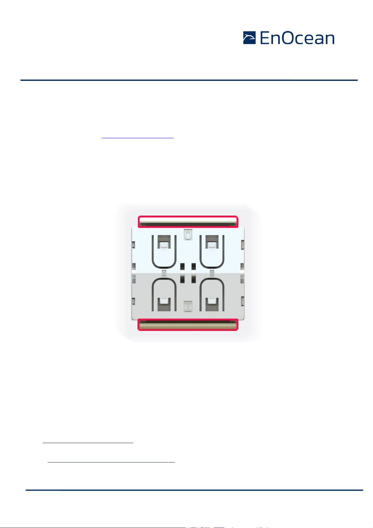
PTM 21x devices contain an electro-dynamic energy transducer which is actuated by a bow.
Figure 2 Drawing with highlighted energy bow
This bow is pushed by an appropriate push button, switch rocker or a similar construction
mounted onto the device. An internal spring will release the energy bow as soon as it is not
pushed down anymore.
When the energy bow is pushed down, electrical energy is harvested and a radio telegram is
transmitted. Releasing the energy bow similarly generates energy which is used to transmit
an another radio telegram.
1
https://www.enocean.com/en/products/
Page 7
© 2020 EnOcean | www.enocean.com PTM 210 / PTM 215 / PTM 215U / PTM 215J User Manual November 2020 | Page 7/48
USER MANUAL
PTM 210 / PTM 215 / PTM 215U / PTM 215J
DC Step code and later
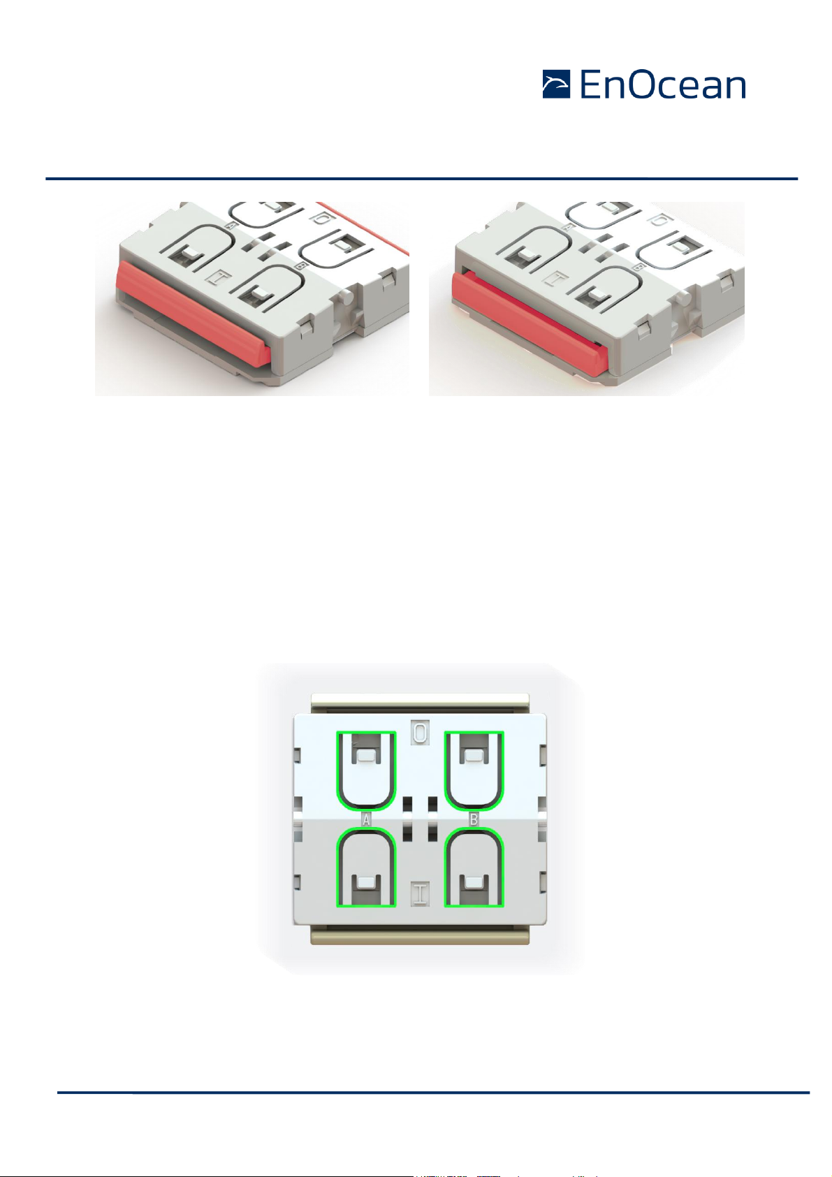
Figure 3 Energy bow released & pressed
It is therefore possible to distinguish between radio telegrams sent when the energy bow was
pushed and radio telegrams sent when the energy bow was released. This makes it possible
to distinguish between button press and button release actions.
By identifying these different telegrams types and measuring the time between pushing and
releasing at the receiver, it is possible to distinguish between “Long” and “Short” push button
presses. This enables simple implementation of applications such as dimming or blinds control.
The radio telegram used by PTM 21x devices identifies the status of the four contact nipples
when the energy bow was pushed or released. This enables the implementation of up to two
switch rockers or up to four pushbuttons.
Figure 4 Drawing with highlighted coding nipples
Page 8
© 2020 EnOcean | www.enocean.com PTM 210 / PTM 215 / PTM 215U / PTM 215J User Manual November 2020 | Page 8/48
USER MANUAL
PTM 210 / PTM 215 / PTM 215U / PTM 215J
DC Step code and later
All PTM 21x devices support two operating modes - a normal mode and a secure mode with
rolling code encryption to enable use in secure applications.
Additionally, to the EnOcean Radio interface the PTM 215 modules include a NFC interface
for device configuration. This NFC interface is powered by the NFC field of an NFC Reader or
an NFC capable smartphone. This makes the communication with the PTM 215 modules possible even when the PTM is not being actuated. With a smartphone and an App e.g. EnOcean
Tool or with an NFC Reader and a PC tool e.g. EnOcean NFC Configurator it is therefore
possible to read information about the PTM module and write configuration parameters.
1.3 Typical Applications
PTM 21x modules are commonly used in the following areas:
Building installation
Industrial automation
Consumer electronics
Key products include wall-mounted switches and handheld remote controls supporting up to
two rockers or up to four pushbuttons.
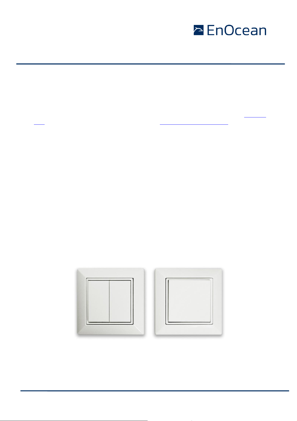
Please find below two examples of an PTM module assembled into a white housing. The left
example shows a double rocker application and the right a single rocker application. This is
commonly used in the European market. A wide range of custom designs with different
shapes, materials and colours can be used together with PTM modules as long they respect
the standardized mechanical interface. Refer to the PTM module mounting instructions for
details [1]. This allows customizable designs with well tested and promoted PTM modules.
Figure 5 Example of an assembled PTM Module (single and double rocker wall switch)
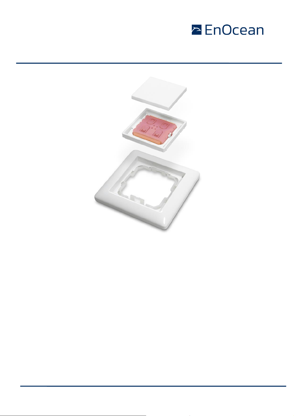
To illustrate the stack up in complete switch please find below an explosion drawing showing a possible switch frame mounting with highlighted PTM module highlighted red.
Page 9
© 2020 EnOcean | www.enocean.com PTM 210 / PTM 215 / PTM 215U / PTM 215J User Manual November 2020 | Page 9/48
USER MANUAL
PTM 210 / PTM 215 / PTM 215U / PTM 215J
DC Step code and later
Figure 6 Explosion drawing of complete wall switch with highlighted PTM Module
Page 10

© 2020 EnOcean | www.enocean.com PTM 210 / PTM 215 / PTM 215U / PTM 215J User Manual November 2020 | Page 10/48
USER MANUAL
PTM 210 / PTM 215 / PTM 215U / PTM 215J
DC Step code and later
1.4 Technical Data
Power supply Electro-dynamic power generator
Antenna PCB antenna
Frequency PTM 210: 868.300 MHz (ASK)2
PTM 215: 868.300 MHz (ASK)
1
PTM 215U: 902.875 MHz (FSK)
PTM 215J: 928.350 MHz (FSK)
Data rate 125 kbps
Conducted output power PTM 210 / PTM 215 / PTM 210U: +5 dBm
PTM 210J: 0 dBm
Channels Two channels with two pushbuttons per channel
Four action states per channel (upper/lower/pressed/not pressed)
EnOcean Radio Standard ERP1 based on ISO/IEC 14543-3-10: PTM 210, PTM 215
ERP2 based on ISO/IEC 14543-3-11: PTM 215U, PTM 215J
EnOcean Equipment Profile supported F6-02-xx, F6-04-xx (normal mode)
D2-03-00 (secure mode)
Security mode Rolling code with AES128
Transmission range PTM 210 / PTM 215 / PTM 210U: typ. 300 m free field, typ. 30 m indoor
PTM 210J: typ. 200m free field, typ. 30m indoor
Device identifier Individual 32 or 48 bit ID (factory programmed)
Redundant sub-telegram count per radio transmission 3 normal mode / 2 secure mode
Radio approvals RED 2014/53/EU (PTM 210 / 215)
IC/FCC CFR-47 Part 15 (PTM 215U)
ARIB STD-T108 (PTM 215J
1.5 Mechanical Interface
Device dimensions (inclusive rotation axis and energy bow) 40.0 x 40.0 x 11.2 mm
Device weight 20 g ± 1 g
Energy bow travel / operating force 1.8 mm / typ. 9 N
At room temperature
Restoring force at energy bow typ. 0.7 N to 4 N
Minimum restoring force of 0.5 N is required for correct operation
Number of operations at 25°C typ. 100.000 actuations tested according to EN 60669 / VDE 0632
Cover material Hostaform (POM)
Energy bow material PBT (50% GV)
2
According the international standard for energy harvesting wireless radio protocol for self-powered applications:
ISO/IEC 14543-3-10
Page 11
© 2020 EnOcean | www.enocean.com PTM 210 / PTM 215 / PTM 215U / PTM 215J User Manual November 2020 | Page 11/48
USER MANUAL
PTM 210 / PTM 215 / PTM 215U / PTM 215J
DC Step code and later
1.6 Environmental Conditions
Operating temperature -25 °C up to +65 °C3
Storage temperature -25 °C up to +65 °C
Humidity 0% to 95% r.h.
Typical max. temperature difference between the PTM module (TX) and a receiver
(RX) should not be bigger than 60 C°.
1.7 References
[1] Mounting Instructions PTM
https://www.enocean.com/products/enocean_modules/ptm-215/
[2] 2D and 3D model for PTM Rockers
https://www.enocean.com/products/enocean_modules/ptm-215/
[3] Enocean Alliance Standards (incl. EEP, Security, Labelling, NFC)
https://www.enocean-alliance.org/specifications/
[4] EnOcean Radio Protocol 1&2
https://www.enocean.com/en/support/knowledge-base/
3
Operation below – 10°C might result in reduction of redundant sub telegram counts by 1.
Page 12
© 2020 EnOcean | www.enocean.com PTM 210 / PTM 215 / PTM 215U / PTM 215J User Manual November 2020 | Page 12/48
USER MANUAL
PTM 210 / PTM 215 / PTM 215U / PTM 215J
DC Step code and later
2 FUNCTIONAL DESCRIPTION
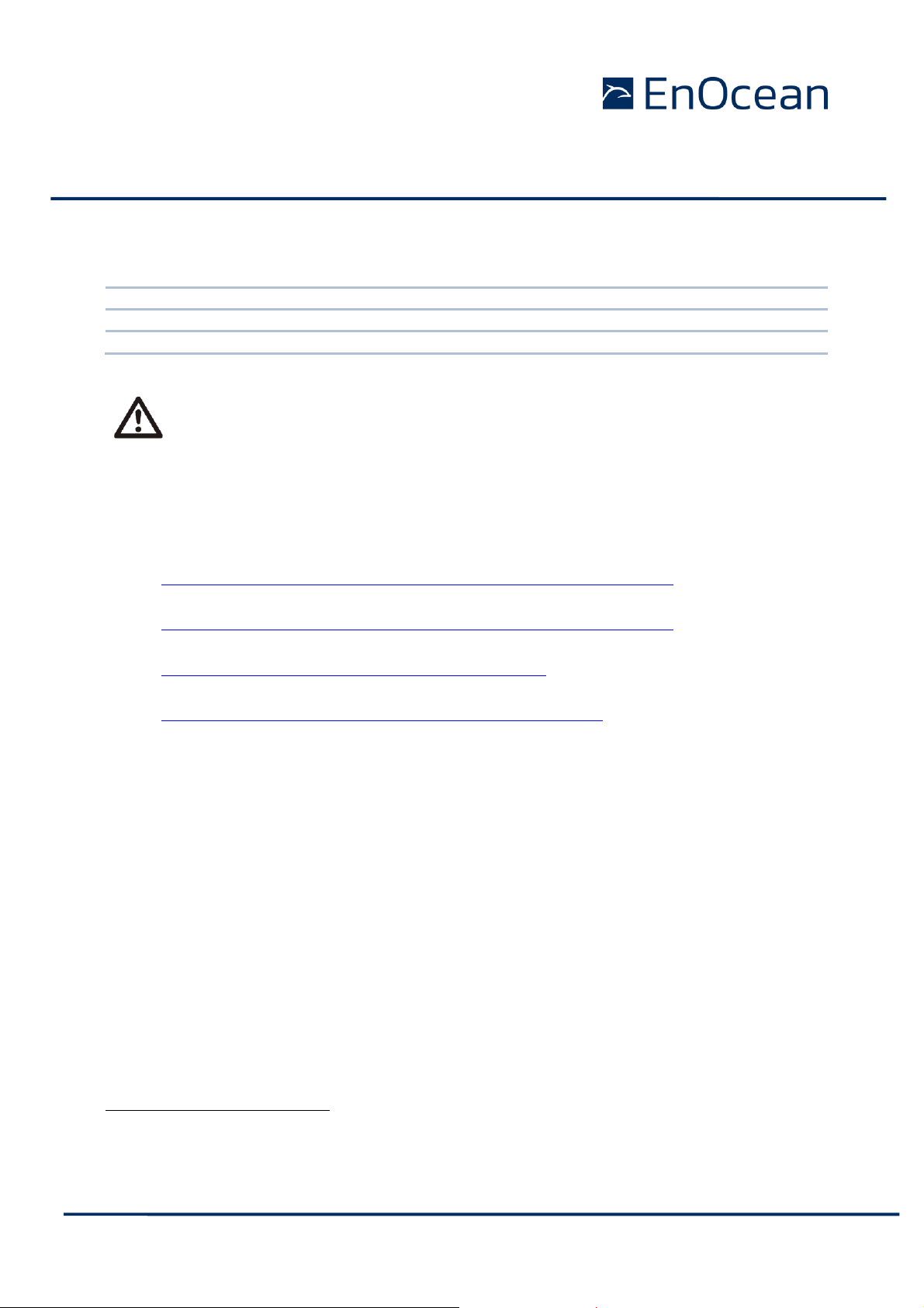
2.1 Block Diagram
Figure 7 Block diagram of PTM 21x
Energy Generator / Energy Bow
Converts the motion of the energy bow into electrical energy. This is the main energy
source for the operation of PTM Modules.
Energy Converter
Converts the energy of the energy generator into a stable DC supply voltage for the device
electronics.
Energy Management
Secures energy supply of the module for the required period. The generator provides an
burst of energy which needs to be conserved for the much longer period than the burst
lasts.
Microcontroller
Determines the status of the contact nipples and the energy bow, encodes this status into a
EnOcean Data telegram, if required it encrypts this data and computes the authentication
signature, generates the proper radio telegram structure and sends it to the radio
transmitter.
RF Transmitter
Transmits the data as a series of short EnOcean radio telegrams.
Contact Nipples
Via the 4 contact nipples the rockers or other custom plastics can code specific information
into the radio telegram triggering different functions at the receiver.
Page 13
© 2020 EnOcean | www.enocean.com PTM 210 / PTM 215 / PTM 215U / PTM 215J User Manual November 2020 | Page 13/48
USER MANUAL
PTM 210 / PTM 215 / PTM 215U / PTM 215J
DC Step code and later
NFC Interface
The NFC interface represents the second communication interface of the PTM and it is designed for commissioning of the PTM device. Using the NFC module information, modes and
runtime parameters can be read and in selected parameters also written.
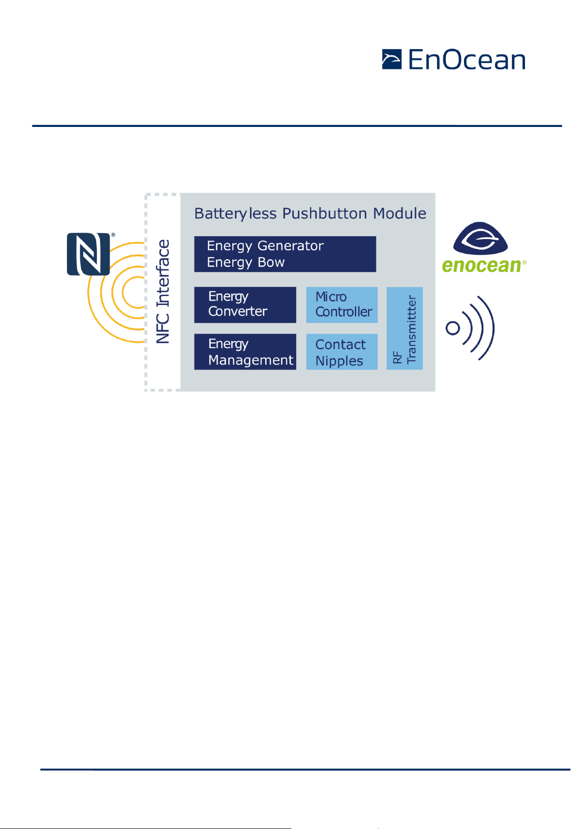
2.2 Contact Nipples Assignment
PTM 21x devices provide four contact nipples. They are grouped into two channels (Channel
A and Channel B) each containing two contact nipples (State O and State I). Resulting the
nipples are referred to as: AO, AI, BO and BI.
The state of all four contact nipples is transmitted together with a unique device identification
whenever the energy bow is pushed or released as a part of an EnOcean radio telegram. The
exact encoding is defined in the EEP Profile. Which EEP is used is based on the Radio Standard
(ERP1 or ERP2) and operating mode (normal or secure). See chapter 2.3 for details on used
EEPs.
The picture below shows the arrangement of the four nipples and their designation:
Figure 8 Contact nipple designation
2.3 Available EnOcean Equipment Profiles
The (EnOcean Equipment Profile) EEP profile defines how the data inside the EnOcean telegram is encoded. It practically means how the nipples and energy bow state are represented
Page 14
© 2020 EnOcean | www.enocean.com PTM 210 / PTM 215 / PTM 215U / PTM 215J User Manual November 2020 | Page 14/48
USER MANUAL
PTM 210 / PTM 215 / PTM 215U / PTM 215J
DC Step code and later
in the radio telegram. Based on the EEP the receiver knows how to interpret telegrams received from a PTM module.
In contrast to sensors which usually support one profile at a time, the encoding of PTM module
does not vary between profiles (RPS profiles) and it up to the receiver to decide how the data
should be interpreted. The receiver can describe what action (switch on / off the light, dim
up / down, move shutters, …) to take. This makes PTM modules very flexible to use.
The table below summarizes the EEP supported by the different members of the PTM 21x
product family.
Normal Mode
Secure Mode
ERP 1
(PTM 210, PTM 215)
F6-01-01
F6-02-01
F6-02-02
F6-02-03
F6-04-01
D2-03-00
ERP 2
(PTM 215J, PTM 215U)
F6-02-04
F6-04-02
D2-03-00
Table 2 Possible EEPs
For the normal mode profiles (Starting with F6) there is no EEP Teach-in message sent. For
secure mode profile (starting D2) there is Secure Teach In. See chapter 3.2.3 for details.
TCM 515U and TCM 310U convert ERP2 profiles to EPR1 profiles internally. On the
ESP3 interface the messages look like “ERP1”.
Due to the mechanical hysteresis of the energy bow, in most rocker switch device
implementations, pressing the rocker sends an N-message and releasing the
rocker sends a U-message.
Note that PTM 21x in will not send a data telegram when pressing 2, 3 or 4 nipple
SBC and actuating the energy bow. This button combination is reserved for mode
change. Please see chapter 3.3 for details.
Page 15

© 2020 EnOcean | www.enocean.com PTM 210 / PTM 215 / PTM 215U / PTM 215J User Manual November 2020 | Page 15/48
USER MANUAL
PTM 210 / PTM 215 / PTM 215U / PTM 215J
DC Step code and later
3 OPERATING MODES
This chapter describes the standard “out of the box” behaviour of PTM 21x devices. This
standard behaviour e.g. mode selection or secure teach-in telegram transmission can be
altered by the NFC Interface. Please refer to the chapter 5.4 for details.
PTM 21x devices support two operating modes:
Normal mode
Secure mode, this mode has two additional sub options
o Implicit RLC (legacy, not recommended)
o Explicit RLC (recommended)
In production the PTM 21x is set into “normal mode” operation. This is therefore the “out of
the box” behaviour of PTM 21x devices.
3.1 Normal Mode Operation
In normal mode, PTM 21x transmits telegrams in the EEP profile respectively defined by ERP1
or ERP2. Please refer to Chapter 2.3. for details.
In Normal mode, transmission of PTM 21x modules is secured by the secure concept includes
unique transmitter IDs. This means EnOcean products cannot be configured to transmit with
identical transmitter ID except for the special case of Base IDs.
3.2 Secure Mode Operation
While operating in secure mode, the PTM 21x sends secure telegrams in accordance to
EEP D2-03-00. Please refer to Chapter 2.3. for details.
In secure mode, the PTM modules use advanced security protection with data encryption and
message authentication. These mechanisms offer effective protection against a series of different attacks. One of the most concerning are Eavesdropping and Replay attacks.
Eavesdropping means somebody can receive and interpret the data correctly. Replay attacks
means an intruder receives and records the message to be retransmitted (replayed) later in
order to trigger an action.
An illustration of these attack scenarios are shown in the figure below.
Page 16

© 2020 EnOcean | www.enocean.com PTM 210 / PTM 215 / PTM 215U / PTM 215J User Manual November 2020 | Page 16/48
USER MANUAL
PTM 210 / PTM 215 / PTM 215U / PTM 215J
DC Step code and later
Figure 9 Example of harmful attacking scenarios PTM Modules are protected from
For details on the secure mechanisms please refer to the security specification of the EnOcean
Radio Protocol [3] together with the examples given in the application note4.
Secure telegrams include a rolling code based on an incrementing counter (RLC) which guarantees that identical message content will be encrypted differently.
The counter can be:
Included in each data message - explicit (recommended)
Or
Not included in data messages – implicit (legacy, not recommended)
The counter value is also part of the teach-in telegram. The selection if the counter is implicit
or explicit is done via the NFC interface (see chapter 5.3.4.3) or special button combinations
at mode switching (see chapter 3.3).
There is no advantage in term of being “more secure” or “more protected” by using the
implicit mode over explicit or vice versa. The “protection level” and security mechanisms are
identical.
The RLC counter bit-size (24 bit explicit mode) practically ensures no “run over” will ever
occur and one RLC value is never reused during the PTMs lifetime twice. It is initialized to 0
at production.
4
http://www.enocean.com/fileadmin/redaktion/pdf/app_notes/AN509_Over-
view_of_EnOcean_Security_features.pdf
Page 17

© 2020 EnOcean | www.enocean.com PTM 210 / PTM 215 / PTM 215U / PTM 215J User Manual November 2020 | Page 17/48
USER MANUAL
PTM 210 / PTM 215 / PTM 215U / PTM 215J
DC Step code and later
The RLC counter is internally restarted to 0x0 once the AES key was changed via the NFC
interface.
After executing a factory reset (see chapter 3.4 for details), the PTM module returns to using
the factory set security key but does not reset the RLC counter associated with the key. The
last used RLC value associated with the factory security set key will be used.
3.2.1 Implicit RLC – legacy, not recommended
This mode is relevant only for the European market (868 MHz) because of certain legacy
receivers. For the J and U market 928 MHz and 902 MHz, there are no such legacy receivers
and thus this mode is completely deprecated in these markets.
The initial RLC counter value is transmitted from PTM 21x to the receiver only as part of the
teach-in telegram. Subsequent secure telegrams do not include it. Therefore, receiver has to
automatically increment its counter at every received telegram to keep it synchronized with
the PTM Module.
When telegrams are not received by the receiver then this may lead to a de-synchronization
of the RLC counter in the PTM module and the RLC counter in the receiver, i.e. the PTM
module counter will have a greater value than the receiver counter.
In order to mitigate this issue, the receiver will usually test the received rolling code against
a defined number – a window - of future expected rolling codes. If a RLC from within the
window can be validated then the receiver will resynchronize its counter automatically to the
new value.
The size of this rolling code window is defined on the receiver side.
For the correct function it is essential that the number of consecutive, non-received telegrams
does not exceed the size of this window.
3.2.2 Explicit RLC – recommended
This is the recommended secure mode for all frequencies and new applications.
In this mode the PTM module sends the RLC value as part of every data telegram. With
transmission of the RLC in every data telegram a desynchronization of the RLC counters
between receivers and transmitter like described above cannot happen.
The receiver uses the RLC value inside the radio telegram to decrypt and authenticate the
received message. The receiver has to check if the received RLC is higher than the last known
value and he does not have to apply any RLC window search mechanism.
3.2.3 Security Teach-in
The Security teach-in includes required information for the receiver to decrypt future data
communication. A security teach-in telegram is sent by PTM 21x after:
Page 18

© 2020 EnOcean | www.enocean.com PTM 210 / PTM 215 / PTM 215U / PTM 215J User Manual November 2020 | Page 18/48
USER MANUAL
PTM 210 / PTM 215 / PTM 215U / PTM 215J
DC Step code and later
Executing the special button combination for secure mode 2x nipple SBC or 3x nipple
SBC – see chapter 3.3 for details.
Trigger through the NFC interface.
Key Secure Teach-in Parameters are specified as following:
Type of the Teach-in_info in the secure teach-in telegram (Teach_In_Info : Type)
is: 1-PTM.
Info of the Teach-in_info in the secure teach-in telegram (Teach_In_Info : Info)
is: 0-Rocker A / 1-Rocker B.
The opposite nipple (e.g. A0&AI or B0&BI) of the used 2xSBC or 3xSBC define the
rocker value (Rocker A or Rocker B) .
When then Secure Teach-in is triggered by NFC then the rocker is used which was
used to generate energy and transmit the Secure Teach-in telegram. If both or no
rocker was used, then Rocker A is coded.
SLF is set to:
o For implicit RLC (legacy, not recommended)
24 bit MAC, VAES Encryption, 16 bit RLC, RLC no TX:
o For explicit RLC (recommended)
24 bit MAC, VAES Encryption, 24 bit RLC, RLC TX
Due to the total length of the Security Teach-In message it needs to be separated in two
distinct telegrams. First part is transmitted at energy bow pressed and second at energy bow
released. For a successful transmission both parts need to be transmitted and received.
For more information on the structure of the teach-in telegram please refer to the EnOcean
Security specification [3].
If the teach-in process is not successful, please repeat the procedure. Due to the
enhanced telegram length of teach-in telegrams in secure mode only a single
teach-in sub-telegram is sent at every actuation (no redundancy).
3.3 Switching between modes
PTM 21x can be switched between normal mode and the secure modes by a special button
combination SBC. There are three types of SBC:
2 nipple SBC – pressing both nipples of a channel i.e. AI & AO or BI & BO.
This SBC is used to enter the secure mode with implicit RLC – legacy, not recommended. The picture below shows both variants of this combination.
Page 19

© 2020 EnOcean | www.enocean.com PTM 210 / PTM 215 / PTM 215U / PTM 215J User Manual November 2020 | Page 19/48
USER MANUAL
PTM 210 / PTM 215 / PTM 215U / PTM 215J
DC Step code and later
Figure 10 2 nipple SBC - channel A left, channel B right
3 nipple SBC – pressing any 3 nipples, which results in 4 different combinations.
This SBC is used to enter the secure mode with explicit RLC.
The picture below shows the possible options for this SBC.
Figure 11 3 nipple SBC - 4 different options
4 nipple SBC – pressing all 4 nipples.
This SBC is used to enter the normal mode and execute factory reset.
The Picture below illustrates this.
Figure 12 4 nipple SBC
To execute a mode change using any of these SBC, the energy bow must be activated in a
defined sequence simultaneously. The SBC must be hold for the complete sequence.
The following transitions apply:
Page 20

© 2020 EnOcean | www.enocean.com PTM 210 / PTM 215 / PTM 215U / PTM 215J User Manual November 2020 | Page 20/48
USER MANUAL
PTM 210 / PTM 215 / PTM 215U / PTM 215J
DC Step code and later
2 SBC
3 SBC
4 SBC
Energy bow
1# press
N/A
N/A
Switch to
Normal
Mode
Energy bow
1# press/release
Transmit secure teach in – if
current mode is security with
implicit RLC.
Transmit secure teach in – if
current mode is security with
explicit RLC.
N/A
Energy bow
1# press/release
2# press
Switch to Security mode with
implicit RLC & transmit secure teach-in (first part).
Switch to Security mode with
explicit RLC & transmit secure teach-in (first part).
N/A
Energy bow
1# press/release
2# press/release
Transmit secure teach-in (second part).
Transmit secure teach-in (second part).
N/A
Table 3 Transition table
The secure teach-in second part is transmission is automatically executed by the PTM module
at the release action regardless what nipples are pressed or not pressed.
Before changing the operating mode please make sure to clear the device from all
receivers which have been teached-in with this device before. Otherwise the receiver will ignore the telegrams and the application will not work.
3.4 Factory Reset
The PTM module can execute a factory reset to return to the defined factory defaults. All
changes done via SBC or the NFC interface with the exception of the following will be reset:
Custom NFC message described in chapter 5.3.2.
The factory reset is executed with the 4 nipple SBC and simultaneously the sequence of 7x
times pressing & releasing the energy bow.
Page 21

© 2020 EnOcean | www.enocean.com PTM 210 / PTM 215 / PTM 215U / PTM 215J User Manual November 2020 | Page 21/48
USER MANUAL
PTM 210 / PTM 215 / PTM 215U / PTM 215J
DC Step code and later
4 RADIO COMMUNICATION
The PTM module transmits radio telegrams based on the EnOcean Alliance Radio standard.
The Radio standard uses the ISO/IEC standard on the lowest protocol level.
There are two version of the EnOcean Radio Protocol:
1. “EnOcean Radio Protocol 1” – ERP 1 based on ISO/IEC 14543-3-10 mostly present in
Europe & China
2. “EnOcean Radio Protocol 2” – ERP 2 based on ISO/IEC 14543-3-11 mostly present in
US & Japan
The used radio standard defines the radio telegram structure. In the ERP1 there is also a
difference between ultra-low power (ULP) frames and common frames.
4.1 ERP 1 Communication
The ERP1 uses different radio telegram structures depending on the operation mode of the
PTM module. These structures are:
Normal mode uses “normal mode ULP”
Secure mode with implicit RLC – legacy, not recommended uses “Secure mode ULP”
Secure mode with explicit RLC – recommended uses “Encrypted RPS Telegram”
The above-mentioned telegram frames are described in the chapters below.
4.1.1 ULP Frames
To save energy the ULP Frames have effectively less payload than the common telegrams.
The ULP Telegrams are also described in the EnOcean Alliance Air Interface Certification [3].
4.1.1.1 Normal mode ULP
The normal mode ULP has total length of 6 bytes. The common frame (RPS), which the ULP
is extend to, is 8 bytes long.
Please consider that EnOcean based receivers & repeaters will transform the ULP telegrams
to common frames by default.
Page 22

© 2020 EnOcean | www.enocean.com PTM 210 / PTM 215 / PTM 215U / PTM 215J User Manual November 2020 | Page 22/48
USER MANUAL
PTM 210 / PTM 215 / PTM 215U / PTM 215J
DC Step code and later
Figure 13 Normal mode ULP substitution to RPS
RORG
The ULP has a value of 0x5 or 0x6 defined by the switch action. It is described in the
EEP, see chapter 2.3 for details on the EEP. It is then substituted to 0xF6 (RPS).
DATA
Is defined as payload of the EEP, see chapter 2.3 for details on EEP. No change during
extension.
TXID
Represents the EnOcean Unique ID. No change during extension.
STATUS
Is created according to the EEP and EPR 1 specification.
HASH
A 4-bit CHECKSUM in extended to an 8 bit CRC or CHECKSUM. For details please see
the ERP 1 specification [4].
4.1.1.2 Secure mode ULP
The secure mode ULP follows the same concept. The payload is reduced to save energy.
Page 23

© 2020 EnOcean | www.enocean.com PTM 210 / PTM 215 / PTM 215U / PTM 215J User Manual November 2020 | Page 23/48
USER MANUAL
PTM 210 / PTM 215 / PTM 215U / PTM 215J
DC Step code and later
Figure 14 Secure mode ULP substitution to encrypted RPS
RORG
The secure low power switch RORG field code 0x7F is substituted by the secure tele-
gram RORG (0x30) defined in the EnOcean Security Specification [3].
DATA
Is defined as payload of the EEP, see chapter 2.3 for details on EEP. No change in field
when extended.
MAC
Message Authentication Cypher – defined in the EnOcean Security Specification. No
change in this field when extended.
TXID
Represents the EnOcean Unique ID. On substitution the field is extended by 1 byte in
the MSB position with 0xFE.
STATUS
Is created according the EEP and EPR 1 specification.
HASH
A 4-bit CHECKSUM in extended to an 8 bit CRC or CHECKSUM. For details please see
the ERP 1 specification [4].
4.1.2 Common Frames
4.1.2.1 Encrypted RPS Telegram
The secure mode ULP supports only a selected type of Security Level Format - SLF. It does
not support SLF with transmission of RLC – “explicit RLC”. To use SLFs with explicit RLC the
definition had to be extended. Instead of redefining the secure mode ULP, the common RPS
with encryption was used. This combination did not require any additional specification work.
Page 24

© 2020 EnOcean | www.enocean.com PTM 210 / PTM 215 / PTM 215U / PTM 215J User Manual November 2020 | Page 24/48
USER MANUAL
PTM 210 / PTM 215 / PTM 215U / PTM 215J
DC Step code and later
For details on encrypted RPS telegrams please see the EnOcean Security specification [3].
4.2 ERP 2 Communication
The ERP2 frames are fully described by the ERP2 specification. In the ERP2, there are no ULP
frames defined and the PTM module uses the common definition. The ERP2 frame is defined
as follows:
The relevant fields are defined below, for other fields and details please consult the ERP2
specification. Optional Data is not used in any type of the PTM module telegram.
4.2.1 Normal Mode Telegram
HEADER
ADDRESS CONTROL: 0b001: Originator-ID 32 bit; no Destination-ID
EXT. HEADER: 0b0: No extended header
TELERGAM TYPE: 0b0000: RPS telegram (0xF6)
DATA OF DATALINK LAYER
Is defined as payload of the EEP, see chapter 2.3 for details on EEP.
4.2.2 Secure Mode Telegram
HEADER
ADDRESS CONTROL: 0b001: Originator -ID 32 bit; no Destination-ID
EXT. HEADER: 0b0: No extended header
TELERGAM TYPE: 0111: Secure telegram (0x30)
DATA OF DATA LINK LAYER
Is defined as payload of the EEP, see chapter 2.3 for details on EEP.
4.3 Redundant transmission
Both EnOcean Radio standards include a safety mechanism for redundant telegram transmission. This means each data transmission (aka sub-telegram) is repeated in random timings
to increase probability of unimpaired reception. It is sufficient to receive at least one subtelegram. The redundant sub-telegrams are 100% identical. The amount of redundant subtelegrams is defined by the selected mode and telegram length.
Following are listed the amounts of the different telegram types:
- Normal mode data telegrams 3 sub-telegrams
- Secure mode data telegrams 2 sub-telegrams
Page 25

© 2020 EnOcean | www.enocean.com PTM 210 / PTM 215 / PTM 215U / PTM 215J User Manual November 2020 | Page 25/48
USER MANUAL
PTM 210 / PTM 215 / PTM 215U / PTM 215J
DC Step code and later
5 CONFIGURATION VIA NFC – PTM 215 / PTM 215J / PTM 215U
5.1 NFC Interface Overview
PTM 215 implements an NFC configuration interface that can be used to access (read and
write) the PTM 215 configuration memory and thereby configure the device as described in
the following chapters.
NFC communication distance is for security reasons set to require direct contact between the
NFC reader and the PTM 215 device.
The NFC interface of PTM 215 uses NFC Forum Type 2 Tag functionality as specified in the
ISO/IEC 14443 Part 2 and 3 standards. It is implemented using an NXP NT3H2111 Mifare
Ultralight tag.
For specific implementation aspects related to the NXP implementation in NT3H2111, please
refer to the NXP documentation which at the time of writing was available under this link:
https://www.nxp.com/docs/en/data-sheet/NT3H2111_2211.pdf
For a detailed description about the NFC functionality, please refer to the ISO/IEC 14443
standard.
5.2 NFC Access Protection
Protected data access is only possible after unlocking the configuration memory with the
correct 32-bit PIN code. By default, the protected area is locked and the default pin code for
unlocking access is 0x000E215.
The default pin code shall be changed to a user-defined value as part of the installation
process. This can be done by unlocking the NFC interface with the old PIN code and then
writing the new PIN code. For details please refer to chapter 5.3.
5.3 NFC Parameters – Memory Map
The NFC memory is organized in pages (a page is the smallest addressable unit) where each
page contains 4 byte of data. Several pages with similar functionality form an NFC memory
area.
These NFC pages are allocated into the following areas:
1. NDEF based (UTF-8)
Device Identification NDEF string (Public read-only access; no PIN required)
This area contains an NDEF string identifying key device parameters
User Information NDEF string (Public read / write access; no PIN required)
This area allows any user to read or write information about the device such as the
intended installation location or additional instructions.
Page 26

© 2020 EnOcean | www.enocean.com PTM 210 / PTM 215 / PTM 215U / PTM 215J User Manual November 2020 | Page 26/48
USER MANUAL
PTM 210 / PTM 215 / PTM 215U / PTM 215J
DC Step code and later
2. Binary data area
NFC HEADER (Public read-only access; no PIN required)
This area contains information about the NFC revision.
CONFIGURATION (Read and Write access, PIN required)
This area contains device configuration registers
INTERNAL DATA (Non-accessible)
This area contains calibration values and internal parameters and cannot be used
The organization of the PTM 215 NFC memory map is shown in Table 4 below.
NFC Address
PIN Required
Operations
Memory Area
Content
0x01 - 0x1F
NO
Read only
PRODUCT NDEF
Device identification NDEF string
0x20 - 0x2F
NO
Read / Write
USER NDEF
User information NDEF string
Dynamic
NO
Read only
NFC HEADER
NFC memory revision
0x40 - 0x4A
YES
Read / Write
CONFIGURATION
Configuration registers
0x4B – 0x9F
N/A
N/A
INTERNAL DATA
Internal data (Do not use)
Table 4 – PTM 215 NFC memory areas
Page 27

© 2020 EnOcean | www.enocean.com PTM 210 / PTM 215 / PTM 215U / PTM 215J User Manual November 2020 | Page 27/48
USER MANUAL
PTM 210 / PTM 215 / PTM 215U / PTM 215J
DC Step code and later
5.3.1 Device Identification NDEF
The NDEF area contains a device identification string using the NDEF (NFC Data Exchange
Format) standard that is readable by most NFC-capable reader devices (including
smartphones).
The NDEF content can be read also by conventional NTAG commands, but this is then executed in “binary” mode. The conversion to a string is achieved by applying UTF-8 decoding.
The contents of the NDEF container are defined by the EnOcean Alliance Labelling specification. For more details please see [3].
An example device identification string from the NDEF area of a PTM 215 module could be:
6PENO+30S000012345678+1P000B00000053+30PS3001-A215+2PDC22+2Z01234567891234
+3C31+16S01000000
This NDEF string encodes the parameters shown in Table 5 below.
Identifier
Length of data (excl. identifier)
Value
6P
3 characters
Standard: “ENO”
30S
12 characters
EURID (6 byte, variable)
1P
12 characters
EnOcean Alliance Product ID
PTM 215: „000B00000053“
PTM 215U: „000B00000055“
PTM 215J: „000B00000057“
30P
10 characters
Ordering Code
PTM 215: “S3001-A215”
PTM 215U: “S3051-A215”
PTM 215J: “S3061-A215”
2P
4 characters
Step Code and Revision (“DC22”)
2Z
14 characters
NFC UID (14 byte, globally unique)
3C
2 characters
Header Start Address (“31” = 0x31)
16S
8 characters
SW Version
Example: 01000000 = 01.00.00.00
Table 5 – NDEF Parameters
5.3.2 User Information NDEF
The NDEF area allows the user to store a string of up to 64 characters starting at page 0x20
and ending at page 0x2F. The string is formatted in the UTF-8 encoding.
5.3.3 NFC Header
The NFC HEADER area contains information about the NFC memory structure and can therefore be used to distinguish between different NFC memory layouts. The start of the memory
is defined by the Header Start Address from the device identification NDEF, see 5.3.1 for
details.
Page 28

© 2020 EnOcean | www.enocean.com PTM 210 / PTM 215 / PTM 215U / PTM 215J User Manual November 2020 | Page 28/48
USER MANUAL
PTM 210 / PTM 215 / PTM 215U / PTM 215J
DC Step code and later
The structure of the NFC HEADER area is described in detail in the EnOcean Alliance specification - NFC Memory Structure for Eco-system products, for details see reference [3]. Details
are also shown in the table below.
NFC Address
Content
Byte 0
Byte 1
Byte 2
Byte 3
0x31
START (0xE0)
LENGTH (0x0A)
VERSION (0x01)
MAN ID MSB (0x00)
0x32
MAN ID LSB(0x0B)
NFC Struct ID (0x000001)
0x33
REVISION (0x02)
END (0xFE)
UNUSED (0x0000)
Figure 15 – NFC HEADER area structure
The NFC HEADER contains the following fields:
START
This field identifies the start of the NFC header and is always set to 0xE0.
LENGTH
This field identifies the length of the NFC header.
This field is set to 0x0A since the header structure is 10 bytes long.
VERSION
This field identifies the major revision of the NFC specification.
MAN ID
The 16-bit Manufacturer ID is assigned by the EnOcean Alliance.
The field identifies the manufacturer of the device so that manufacturer-specific layout
implementations can be determined.
For EnOcean GmbH products this field is set to 0x000B.
NFC Struct ID
The 24-bit NFC Struct ID field identifies an individual device from the range of devices
manufactured by the manufacturer specified in the Manufacturer ID field.
For PTM 215, the NFC Struct ID is set to 0x000001.
REVISION
The REVISION field identifies the exact revision of the NFC layout.
The REVISION will be incremented whenever a change to the NFC layout is made.
Changes are possible only when 100% backwards compatible to all previous revisions.
If changes are not compatible a new NFC Struct ID must be defined.
END
Page 29

© 2020 EnOcean | www.enocean.com PTM 210 / PTM 215 / PTM 215U / PTM 215J User Manual November 2020 | Page 29/48
USER MANUAL
PTM 210 / PTM 215 / PTM 215U / PTM 215J
DC Step code and later
The END field identifies the end of the NFC header and is always set to 0xFE. The
number of bytes from START to END must equal LENGTH, otherwise the NFC header
is invalid.
5.3.4 Configuration
The CONFIGURATION area allows the configuration of the device parameters. Configuration
registers larger than 8 bit use big endian format, i.e. the most significant byte comes first.
Read or write access to the CONFIGURATION area is only possible after unlocking the memory
using the correct 32-bit PIN code. See chapter 5.2 for details.
Before making any changes to the default configuration, be sure to familiarize yourself with
the functionality of the device and the effect of the intended changes.
The structure of the CONFIGURATION area is defined by the NFC Struct ID as described in
chapter 5.3.3 and is shown in Figure 16 below.
NFC
Address
Content
Byte 0
Byte 1
Byte 2
Byte 3
0x40
FLAG
RFU
0x41
NEW NFC PIN
0x42
SECURITY LEVEL
ALLOW TEACH IN
NEXT OPERATION
IS TEACH IN
RFU
0x43
RFU
0x44
…
0x47
USER KEY (128 Bit)
(Write Only - Will be reset to zero after it has been copied to internal memory)
Can be used as alternative security key instead of FACTORY_KEY
0x48
PRODUCT ID
(String with 12 characters “e.g. 000B00000053” in UTF-8 format – to be copied to NDEF)
0x49
0x4A
Figure 16 – CONFIGURATION area structure
Each field is explained in the following chapters.
5.3.4.1 FLAG
This field needs to be changed to 0x55 to make the PTM application aware of the executed
changes. Without setting this field to 0x55 the changes will not be considered by the PTM
application.
Page 30

© 2020 EnOcean | www.enocean.com PTM 210 / PTM 215 / PTM 215U / PTM 215J User Manual November 2020 | Page 30/48
USER MANUAL
PTM 210 / PTM 215 / PTM 215U / PTM 215J
DC Step code and later
5.3.4.2 NEW NFC PIN
The NFC PIN used to protect access to the CONFIGURATION memory area should be changed
from the default value to a user-specific value to avoid unauthorized access to the NFC device
configuration interface.
To do so, first authenticate with the current NFC PIN and then write the new NFC PIN (32-bit
value) to memory.
The new NFC PIN will be applied to the PTM module after pressing & releasing the energy
bow. Until then, the previous NFC PIN will remain valid to unlock the NFC memory.
5.3.4.3 SECURITY LEVEL
The security level register defines what encryption features are used in the radio transmission. If this register is changed from its default setting via the NFC interface, manual mode
changes via SBC (as described in chapter 3.3) are no longer possible.
Both the 2 nipple SBC and 3 nipple SBC will still trigger the transmission of a Security Teachin if a security mode was selected by NFC. In this case the Security Teach-in is transmitted
already at the first energy bow press / release.
To re-enable the “mode change by SBC”, a factory reset needs to be executed. The mode
change via NFC remains possible even after a write operation.
The operation and application behaviour of the selected mode is described in chapter 3. Following options can be selected:
0b00000000: Normal mode operation
0b00000001: Secure mode – Implicit RLC legacy
0b00000010: Secure mode – Explicit RLC (recommended)
0b00000011: Defined by SBC (default). This value cannot be set by NFC write
operation.
0b0000 0100 – 0b1111 1111: RFU
5.3.4.4 ALLOW TEACH IN
This flag controls if a Security Teach-in can be triggered by SBC. The Security Teach-in Telegram is described in chapter 3.2.3. The following values can be set:
0b00000000: OFF: SBC will not trigger a secure teach-in telegram or any
other (data) telegram.
0b00000001: ON (default): SBC will trigger a secure teach-in telegram.
0b0000 0010 – 0b1111 1111: RFU
Page 31

© 2020 EnOcean | www.enocean.com PTM 210 / PTM 215 / PTM 215U / PTM 215J User Manual November 2020 | Page 31/48
USER MANUAL
PTM 210 / PTM 215 / PTM 215U / PTM 215J
DC Step code and later
5.3.4.5 NEXT OPERATION IS TEACH IN
The module will send a Security Teach-in telegram the next time it is triggered. The module
must first be set to the desired security level. After the secure Teach in telegram was send
this flag is reset to default state. Following values can be set
0b00000000: OFF (default): Normal operation.
0b00000001: ON: Next telegram will be a Security Teach-in telegram.
0b0000 0010 – 0b1111 1111: RFU
5.3.4.6 PRODUCT ID
The EnOcean Alliance Product ID uniquely identifies each product within the EnOcean Alliance
ecosystem. The Product ID consists of a 2-byte manufacturer identification code (assigned
by EnOcean Alliance) and a 4-byte product identification code (assigned by the manufacturer.
EnOcean has been assigned the manufacturer identification code 0x000B. EnOcean has assigned the following product identification codes to PTM 215:
PTM 215: 0x00000053
PTM 215U: 0x00000055
PTM 215J: 0x00000057
The PRODUCT ID register contains the Product ID in ASCII format (12 characters) and allows
changing both manufacturer and product identification. Changing the PRODUCT ID will also
cause the PRODUCT ID field in the NDEF string (described in chapter 5.3.1) to be updated.
Figure 17 below shows the structure of the PRODUCT ID register. This register contains the
sequence of 12 ASCII characters (1 byte each) starting with CH0 and ending with CH11.
PRODUCT_ID
CH0
CH1
CH2
CH3
CH4
CH5
CH6
CH7
CH8
CH9
CH10
CH11
Manufacturer (“000B”)
Product ID (“00000053”, “00000055” or “00000057”)
Figure 17 – PRODUCT_ID
5.3.4.7 USER_KEY
Each PTM 215 module is pre-programmed at the factory with a randomly generated 128-bit
security key. This key will by default be used to encrypt and authenticate PTM 215 radio
telegrams when operating in security mode. This key is also encoded inside the QR code on
the label of the product.
In certain applications or situations, it might be desirable to assign a different (user-defined)
security key. This can be done by writing the user-defined security key to the USER_KEY.
Page 32

© 2020 EnOcean | www.enocean.com PTM 210 / PTM 215 / PTM 215U / PTM 215J User Manual November 2020 | Page 32/48
USER MANUAL
PTM 210 / PTM 215 / PTM 215U / PTM 215J
DC Step code and later
Once the key was written the PTM 215 will automatically use the new written key and reset
the RLC sequence to 0x0.
To return to the factory defined key a factory reset as described in chapter 3.4 must be
executed.
Note that the USER_KEY register is a write-only register meaning that it is not
possible to read back a user-defined security key.
Page 33

© 2020 EnOcean | www.enocean.com PTM 210 / PTM 215 / PTM 215U / PTM 215J User Manual November 2020 | Page 33/48
USER MANUAL
PTM 210 / PTM 215 / PTM 215U / PTM 215J
DC Step code and later
5.4 NFC Interaction with the PTM Application
The PTM 215 application is not powered by the NFC interface during NFC communication.
After parameters in the NFC memory were changed, the energy bow has to be pressed and
released so that the PTM application can read the new parameters, verify and apply them.
For this purpose, also a special FLAG register must be set to notify the PTM Application about
configuration changes. Description of the FLAG register can be found in chapter 5.3.4.
During the first press / release cycle immediately after an NFC configuration operation, the
PTM module will update its internal parameters according to the provided configuration values
and therefore not execute any radio communication. Afterwards e.g. during the second press
/ release cycle, normal operation will resume.
Configuring the following parameters will change the standard PTM module behaviour as
explained in the chapter 3:
SECURITY LEVEL, Chapter 5.3.4.3, Effect; Switching modes by SBC is not possible.
ALLOW TEACH IN, Chapter 5.3.4.5, Effect: When entering Security Mode by SBC, a
teach-in telegram is not transmitted anymore.
5.5 NFC Interface Tools
To operate the NFC interface of the PTM Modules there are different options:
“EnOcean Tool” is a smartphone app available for iOS and Android
“EnOcean NFC Configurator” is a PC application that can be used in conjunction with
a specific NFC USB Reader
Customer-developed tools
5.5.1 EnOcean Tool
Figure 18 EnOcean Tool Icon
EnOcean Tool is a smartphone application for easy configuration and commissioning of
EnOcean NFC devices such as the PTM 215 module, the STM 550 multisensor or the EMDC
motion detector. This application serves as a configuration interface between NFC devices
Page 34

© 2020 EnOcean | www.enocean.com PTM 210 / PTM 215 / PTM 215U / PTM 215J User Manual November 2020 | Page 34/48
USER MANUAL
PTM 210 / PTM 215 / PTM 215U / PTM 215J
DC Step code and later
and NFC readers such as NFC-enabled smartphones or tablets. It can be used to determine
all essential product parameters.
The app is mainly aimed at OEMs and installers. They can also use the application to integrate
NFC devices into existing systems. EnOcean Tool can be used to optimize the energy consumption of the respective device, monitor the energy-harvesting performance of the integrated solar cell (in sensors) and read out all product information such as product ID or
device recognition. Access to the NFC interface is protected by a user-defined PIN code.
The EnOcean Tool app is available free of charge for the operating systems iOS and Android.
For app downloads, tutorial videos and more details please visit the EnOcean Tool Product
page: https://www.enocean.com/products/enocean-software/enocean-tool/
Direct download possible via these QR codes:
With EnOcean Tool you can configure only selected parameters of the products.
Please check the Help Section of Product Manuals in EnOcean Tool for details.
Figure 19 Help Section in EnOcean Tool
Page 35

© 2020 EnOcean | www.enocean.com PTM 210 / PTM 215 / PTM 215U / PTM 215J User Manual November 2020 | Page 35/48
USER MANUAL
PTM 210 / PTM 215 / PTM 215U / PTM 215J
DC Step code and later
5.5.2 EnOcean NFC Configurator
Figure 20 EnOcean NFC Configurator
EnOcean provides the NFC Configurator for all OEM Partners to configure and commission
EnOcean GmbH products with NFC interface. NFC Configurator is a PC application enabling
to write / read all accessible parameters specified for the product. Configured parameters
can also be stored into a separate file, reopened and shared with other users. It also includes
a simple option to execute batch programming in small numbers and log the process.
The NFC Configurator is designed to work on PC running Windows 10 in conjunction with the
external USB NFC reader TWN4 Multitech 2 HF NFC Reader (order code T4BT-FB2BEL2SIMPL) from Elatec RFID Systems (sales-rfid@elatec.com).
This reader is shown in Figure 21 below.
Figure 21 – Elatec TWN4 MultiTech Desktop NFC Reader
The EnOcean NFC Configurator SW can be downloaded from the EnOcean support & tools
page: https://www.enocean.com/support/download/
5.5.3 Including NFC Functionality into Existing Customer Tools
Reading and writing the NFC memory of the PTM module is done using the common NFC
commands defined by the NFC Forum as described in chapter 5.1. This makes it easy for
OEMs to include NFC configuration functionality into their own tools.
Page 36

© 2020 EnOcean | www.enocean.com PTM 210 / PTM 215 / PTM 215U / PTM 215J User Manual November 2020 | Page 36/48
USER MANUAL
PTM 210 / PTM 215 / PTM 215U / PTM 215J
DC Step code and later
OEMs wanting to develop own NFC configuration tools or to include NFC configuration into
their existing tools can accelerate their development by licensing the EnOcean SW libraries
and the EnOcean reference implementation. Please contact EnOcean: support@enocean.com
for more information or a commercial offer.
Page 37

© 2020 EnOcean | www.enocean.com PTM 210 / PTM 215 / PTM 215U / PTM 215J User Manual November 2020 | Page 37/48
USER MANUAL
PTM 210 / PTM 215 / PTM 215U / PTM 215J
DC Step code and later
6 APPLICATIONS INFORMATION
6.1 Product Label
Listed below are examples of the product labels for each of the PTM 21x modules. Actual
product label has specific product related information. Each module can easily be identified
by its name and the supported frequency (868.300 MHz 902.875 MHz, 928.350 MHz) on the
label. Additionally, PTM 215 devices (which contain the NFC interface for configuration) can
be identified by the NFC icon on the product label.
Figure 22 PTM 215 / PTM 210 EU labels
Figure 23 PTM 215J Japan / 928 MHZ labels
Figure 24 PTM 215U / US labels
Page 38

© 2020 EnOcean | www.enocean.com PTM 210 / PTM 215 / PTM 215U / PTM 215J User Manual November 2020 | Page 38/48
USER MANUAL
PTM 210 / PTM 215 / PTM 215U / PTM 215J
DC Step code and later
The common customer relevant fields of the labelling have the following meaning:
Field
Meaning
Examples
Model
Product name
PTM 210 / PTM 215 / PTM
215J / PTM 215U
Order code
EnOcean Order code
S3001-A210 / S3001A215 / S3051-A215 /
S3061-A215
Step code
Product version
DC / DD / DE etc.
Production date
Week of year / production
Year
40 / 18 (40th week in
2018)
NFC capability information
– showing the position of
the antenna.
Certification marking of the
EnOcean Alliance with frequency specification.
Frequencies: 868.3 MHz,
902.875 MHz, 928.350
MHz
Company name and Unique
EnOcean ID in hexadecimal
48 bit format.
ID: 0x0000 0150 0100
Production tracking in QR
Code
See Chapter 6.2.
Table 6 QR Code containers
Page 39

© 2020 EnOcean | www.enocean.com PTM 210 / PTM 215 / PTM 215U / PTM 215J User Manual November 2020 | Page 39/48
USER MANUAL
PTM 210 / PTM 215 / PTM 215U / PTM 215J
DC Step code and later
6.2 Content of QR codes
Reading the QR code will return a text string formatted according the EnOcean Alliance Labelling standard. Details about the labelling standard can be found here:
https://www.enocean-alliance.org/productid/.
The same standard is also used to specify the NDEF String content.
The QR content example might look like this:
30S000001500100+13Z12345678123456781234567812345678+1P000B00000057+30PS3061A215+2PDC22+S01123456789012
The string holds different information containers joined by “+”. At the begging of every container is an identifier e.g. “30S”. The example string above consists of the following contain-
ers.
Page 40

© 2020 EnOcean | www.enocean.com PTM 210 / PTM 215 / PTM 215U / PTM 215J User Manual November 2020 | Page 40/48
USER MANUAL
PTM 210 / PTM 215 / PTM 215U / PTM 215J
DC Step code and later
Identifier
Value
Length of data
30S
000001500100
Static Source Address (hex),
EnOcean Radio ID 48 bit format
15 characters (12 data)
+
Field Separator
1 character
13Z
12345678123456781234567812345678
Security AES key (16 Bytes), generated and specific for
each device
35 characters (32 data)
+
Field Separator
1 character
1P
000B00000057
Product ID (EnOcean Alliance),
14 characters (12 data)
+
Field Separator
1 character
30P
S3061-A215
Ordering Code (EnOcean module),
13 characters (10 data)
+
Field Separator
1 character
2P
DC22
Step Code - Revision (EnOcean module), e.g.
6 characters (4 data)
+
Field Separator
1 character
S
123456789012
Manufacturer recognition,
01 + DMC/Serial Number,
15 characters (2 + 12 data)
Total: 102 characters
Table 7 QR code content example based on the above table
The length and content of the QR code can vary from the example for the case of different
module revisions.
6.3 Construction of application specific Switch Rockers
EnOcean provides both 2D mechanical data and 3D construction data (in IGS format) of the
mechanical interface of PTM 21x modules for the design of customer specific frames and
rockers. This data is available here:
https://www.enocean.com/produkte/enocean_module/ptm-215/
Polycarbonate is recommended as rocker material since it is both buckling resistant and wearproof. It is also recommended to apply Teflon varnish in the areas of actuation.
Page 41

© 2020 EnOcean | www.enocean.com PTM 210 / PTM 215 / PTM 215U / PTM 215J User Manual November 2020 | Page 41/48
USER MANUAL
PTM 210 / PTM 215 / PTM 215U / PTM 215J
DC Step code and later
It is recommended using non-conductive material for the rockers to ensure best
transmission range. Avoid if possible metallic materials or plastics with conducting
ingredients such as graphite.
If the rocker is not mounted on the rotation axis of PTM 21x several tolerances
have to be considered! The measure from support plane to top of the energy bow
is 7.70 mm +/- 0.3 mm!
The movement of the energy bow must not be limited by mounted rockers!
Catwalks of the switch rocker must not exert continuous forces on contact nipples!
6.4 Device Mounting
For mounting the PTM 21x device into an application specific case, the package outline drawings of the device are given in chapter 1.5. More detailed 3D construction data is available
from EnOcean in IGS format as described in the previous chapter.
It is recommended not to mount the device directly onto metal surfaces or into
metal frames since this can lead to significant loss of transmission range.
PTM is powered by the electromagnetic generator ECO 200. For proper function magnets or
ferromagnetic materials are not permitted within a keep-out zone of 60mm around the centre
of the PTM.
Figure 25 Keep of Area for magnetic and ferromagnetic materials
Page 42

© 2020 EnOcean | www.enocean.com PTM 210 / PTM 215 / PTM 215U / PTM 215J User Manual November 2020 | Page 42/48
USER MANUAL
PTM 210 / PTM 215 / PTM 215U / PTM 215J
DC Step code and later
6.5 Transmission Range
The main factors that influence the system transmission range are:
Type and location of the antennas of receiver and transmitter.
Type of terrain and degree of obstruction of the link path.
Sources of interference affecting the receiver.
“Dead spots” caused by signal reflections from nearby conductive objects.
Since the expected transmission range strongly depends on this system conditions, range
tests should always be performed to determine the reliably achievable range under the given
conditions.
The following figures for expected transmission range are considered by using a PTM, an STM
or a TCM radio transmitter device together with a TCM radio receiver device with preinstalled
whip antenna.
These figures should be treated as a rough guide only:
Line-of-sight connections
Typically 30 m range in corridors, up to 100 m in halls
Plasterboard walls / dry wood
Typically 30 m range, through max. 5 walls
Ferro concrete walls / ceilings
Typically 10 m range, through max. 1 ceiling
Fire-safety walls, elevator shafts, staircases and similar areas should be considered
as shielded
The angle at which the transmitted signal hits the wall is very important. The effective wall
thickness – and with it the signal attenuation – varies according to this angle. Signals should
be transmitted as directly as possible through the wall. Wall niches should be avoided.
Other factors restricting transmission range include:
Switch mounting on metal surfaces (up to 30% loss of transmission range).
Hollow lightweight walls filled with insulating wool on metal foil.
False ceilings with panels of metal or carbon fibre.
Lead glass or glass with metal coating, steel furniture.
The distance between EnOcean receivers and other transmitting devices such as computers,
audio and video equipment that also emit high-frequency signals should be at least 0.5 m.
A more detailed application note on how to determine the transmission range within buildings
is available from: https://www.enocean.com/support/application-notes/
Page 43

© 2020 EnOcean | www.enocean.com PTM 210 / PTM 215 / PTM 215U / PTM 215J User Manual November 2020 | Page 43/48
USER MANUAL
PTM 210 / PTM 215 / PTM 215U / PTM 215J
DC Step code and later
7 AGENCY APPROVALS
7.1 PTM 210 and PTM 215: Radio Approval for the European Market
The module is developed and tested according to the RED EU-directive on radio equipment.
The assembly conforms to the European and national requirements of electromagnetic compatibility. The conformity has been proven and the corresponding documentation has been
deposited at EnOcean. The PTM devices can be operated without notification and free of
charge in the area of the European Union, and in Switzerland.
The following provisos apply:
EnOcean switch modules must not be modified or used outside specification limits.
EnOcean switch modules may only be used to transfer digital sensor data
The final product including EnOcean switch module must meet all necessary application
specific requirement for CE conformity (e.g. product labelling, manual and conformity to
all application specific directives and standards).
If transmitters are used according to the regulations of the 868.300 MHz SRD/ISM band, a
so-called “Duty Cycle” of 1% per hour for each transmitter must not be exceeded. Permanent
transmitters such as radio earphones are not allowed.
For conventional applications, it must be ensured that the PTM 215 or PTM 210 radio device
is not operated more than 6000 times within one hour (one operation: energy bow is pressed
and released). Within this calculation, the extraordinary short telegram length is considered
including three sub-telegrams. Also a tolerance of 5% in the telegram length is included.
Page 44

© 2020 EnOcean | www.enocean.com PTM 210 / PTM 215 / PTM 215U / PTM 215J User Manual November 2020 | Page 44/48
USER MANUAL
PTM 210 / PTM 215 / PTM 215U / PTM 215J
DC Step code and later
7.3 PTM 215U: FCC and Industry Canada Regulatory Statements
This device complies with part 15 of the FCC rules and Industry Canada ICES- 003. Operation
is subject to the following two conditions: (1) This device may not cause harmful interference,
and (2) this device must accept any interference received, including interference that may
cause undesired operation. Any changes or modifications not expressly approved by manufacturer could void the user’s authority to operate the equipment.
When the product is placed on the US / Canadian market, it must carry the Specified Radio
Equipment marking as shown below:
IMPORTANT! Any changes or modifications not expressly approved by the party responsible
for compliance could void the user’s authority to operate this equipment.
Le présent appareil est conforme aux CNR d’Industrie Canada applicables aux appareils radio
exempts de licence. L’exploitation est autorisée aux deux conditions suivantes: (1) l’appareil
ne doit pas produire de brouillage, et (2) l’utilisateur de l’appareil doit accepter tout brouillage
radioélectrique subi, meme si le brouillage est susceptible d’en compromettre le fonctionne-
ment.
IMPORTANT! Tous les changements ou modifications pas expressément approuvés par la
partie responsable de la conformité ont pu vider l’autorité de l’utilisateur pour actioner cet
équipment.
FCC: SZV-PTM215U
IC: 5713A-PTM215U
Page 45

© 2020 EnOcean | www.enocean.com PTM 210 / PTM 215 / PTM 215U / PTM 215J User Manual November 2020 | Page 45/48
USER MANUAL
PTM 210 / PTM 215 / PTM 215U / PTM 215J
DC Step code and later
7.4 PTM 215J: Japanese Type Approval
PTM 215J complies with the Japanese radio law and is certified according to ARIB STD-T108
V1.0 (2012-02). There is a certification marking on the back side of the module.
When the product is placed on the Japanese market, it must carry the Specified Radio Equipment marking as shown below:
If the certification label cannot be recognized from outside (e.g. installation in a host) appropriate information must be referenced in the user manual.
Transmitting the secure teach in telegram the PTM 215J transmits a telegram with 48-bit ID
as required by Japanese radio law.
Page 46

© 2020 EnOcean | www.enocean.com PTM 210 / PTM 215 / PTM 215U / PTM 215J User Manual November 2020 | Page 46/48
USER MANUAL
PTM 210 / PTM 215 / PTM 215U / PTM 215J
DC Step code and later
8 PRODUCT SAFETY INSTRUCTIONS
PTM modules are not end customer sold final products. Final products (e.g. switches) which
include PTM Modules are to be prepared by partners. Please consider following recommendation for parts of the final product safety instructions:
Intended use:
Switch products are intended for indoor usage in closed dry rooms, for de-
tails see user manual.
The product must not be used in any relation with equipment that supports,
directly or indirectly, human/animal health or life or with applications that
can result in danger for people, animals or real value.
The product is not suitable for use in mechanically or environmentally chal-
lenging environments including (but not limited to) environments with heavy
vibrations, mechanical shocks, very high humidity, very dusty or in explosive
atmosphere.
The installation and assembly of electrical equipment may only be performed
by a skilled electrician.
Basic safety instructions:
Risk of suffocation! Do not leave the packaging material lying around. Chil-
dren could swallow the small parts and choke on them.
Install and operate product according to user manual and do not modify the
product.
The product should not be exposed to rapid temperature changes shortly be-
fore or during operation; condensation of moisture has to be avoided.
Wrong cleaning may damage the product; we suggest cleaning with soft and
damp tissue.
Do not disassemble!
Page 47

© 2020 EnOcean | www.enocean.com PTM 210 / PTM 215 / PTM 215U / PTM 215J User Manual November 2020 | Page 47/48
USER MANUAL
PTM 210 / PTM 215 / PTM 215U / PTM 215J
DC Step code and later
9 PRODUCT RELEASES
Below are listed Product releases of
PTM 210
Revision
Date
Key change
CB-26
July 2020
Initial pre-series
DC-27
Sept 2020
Pilot production release.
DC-29
Dec 2020
First mass production release. Bug correction in sec
mode change.
PTM 215
Revision
Date
Key change
CB-21
July 2020
Initial pre-series
DC-22
Sept 2020
Pilot production release.
DC-24
Dec 2020
First mass production release. Bug correction in sec
mode change.
PTM 215U
Revision
Date
Key change
CB-15
July 2020
Initial pre-series
DC-18
Dec 2020
First mass production release.
Page 48

© 2020 EnOcean | www.enocean.com PTM 210 / PTM 215 / PTM 215U / PTM 215J User Manual November 2020 | Page 48/48
USER MANUAL
PTM 210 / PTM 215 / PTM 215U / PTM 215J
DC Step code and later
PTM 215J
Revision
Date
Key change
CB-15
July 2020
Initial pre-series
DC-18
Dec 2020
First mass production release.
 Loading...