

Page 1

PTM 215B BLE Pushbutton Transmitter Module
1
USER MANUAL
PTM 215B – 2.4 GHZ Pusbutton Transmitter Module
9.09.2016
Observe precautions! Electrostatic sensitive devices!
Patent protected:
WO98/36395, DE 100 25 561, DE 101 50 128,
WO 2004/051591, DE 103 01 678 A1, DE 10309334,
WO 04/109236, WO 05/096482, WO 02/095707,
US 6,747,573, US 7,019,241
© 2016 EnOcean | www.enocean.com F-710-017, V1.0 PTM 215B User Manual | v0.8 | September 2016 | Page 1/42
Page 2

Version
Author
Reviewer
Date
Major Changes
0.1
MKA
01.05.2016
Initial Release
0.2
MKA
03.05.2016
Added security handling
0.3
MKA
18.05.2016
Added c ommi ssioning information
0.4
MKA
30.05.2016
Added NFC information
0.5
MKA
08.06.2016
Added Optional Data field
0.6
MKA
14.06.2016
Added NFC addresses
0.7
MKA
12.09.2016
Added EnOcean company identifier
0.8
MKA
19.09.2016
Added r eg ulatory info r mation
USER MANUAL
PTM 215B – 2.4 GHZ Pusbutton Transmitter Module
REVISION HISTORY
The follow ing major modifications an d imp rovements ha ve been made to this document:
Published by EnOcean GmbH , K olpingring 18a, 82041 Ob erhaching, Germany
www.enocean.com, info@enocean.com, ph one + 49 (89) 6734 6890
© EnOcean GmbH, All Rights Reserved
Important!
This information describes the type of component and shall not be considered as assured
characteristics. No responsibility is assumed for possible omissions or inaccuracies. Cir cuitry
and specifications are subject to change without notice. For the latest product specifications, refer to the EnOcean website:
http://www.enocean.com.
As far as patents or other rights of third parties are concerned, liability is only assumed for
modules, not for the described applications, processes and circuits.
EnOcean does not assume responsibility for use of modules described and limits its liability
to the replacement of modules determined to be defective due to workmanship. Devices or
systems containing RF components must meet the essential requirements of the local legal
authorities.
The modules must not be used in any relation with equipment that supports, directly or
indirectly, human health or life or with applications that can result in danger for people,
animals or real value.
Component s of th e m odules ar e cons i dered an d shoul d b e di s posed of as ha zar dous wa ste .
Local gov ernment regula tions are to be obs erved.
Packing: Please use th e recycling operators known to you.
© 2016 EnOcean | www.enocean.com F-710-017, V1.0 PTM 215B User Manual | v0.8 | September 2016 | Page 2/42
Page 3

USER MANUAL
PTM 215B – 2.4 GHZ Pusbutton Transmitter Module
TABLE OF CONTENT
1 GENERAL DESCRIPTIO N ................................................................................. 5
1.1 Basic functionality ......................................................................................... 5
1.2 Technical data ............................................................................................... 6
1.3 Physical dimensions ....................................................................................... 6
1.4 Environmental conditions ............................................................................... 6
1.5 Packa ging informa tion .................................................................................... 6
1.6 Ordering information...................................................................................... 6
2 FUNCTIONAL INFORMATION ........................................................................... 7
2.1 PTM 215B Device Overview ............................................................................. 7
2.2 Basic Func tionality ......................................................................................... 7
2.3 Block Diagram .............................................................................................. 8
2.4 User Interface ............................................................................................... 9
2.5 PTM 215B radio channel parameters .............................................................. 10
2.5.1 PTM 215B radio transmission sequence .................................................. 10
2.6 PTM 215B button action encod ing .................................................................. 11
2.7 PTM 215B commissioning ............................................................................. 12
2.8 Operation modes ......................................................................................... 13
2.8.1 Data mode .......................................................................................... 13
2.8.2 Radio-based commissioning mode ......................................................... 14
2.8.2.1 Commissioning mode entry ................................................................ 14
2.8.2.2 Commissioning telegr am tran s mission ................................................. 15
2.8.2.3 Exit from commiss ioning mode ........................................................... 15
2.9 BLE frame structure ..................................................................................... 16
2.9.1 Preamble ............................................................................................ 16
2.9.2 Access Address .................................................................................... 16
2.9.3 Header ............................................................................................... 16
2.9.4 Source address .................................................................................... 17
2.9.4.1 Static source address mode ................................................................ 17
2.9.4.2 Private resolvable source address mode ............................................... 18
2.9.5 Check Sum ......................................................................................... 19
2.9.6 Payload .............................................................................................. 20
2.9.6.1 Data Telegram Payload ...................................................................... 20
2.9.6.2 Commissioning Telegram Payload ....................................................... 21
2.10 Telegram authentication ............................................................................... 22
2.10.1 Authe n ti c a t io n implementa tion .............................................................. 23
2.11 NFC interface .............................................................................................. 24
2.11.1 Configuration memory organization........................................................ 24
2.11.2 Memory Address Map ........................................................................... 25
2.11.3 Public data .......................................................................................... 26
2.11.4 Protected Data .................................................................................... 26
2.11.4.1 PIN Code ......................................................................................... 27
2.11.4.1 Modifying product parameters ............................................................ 27
2.11.4.2 Source Address Write regi s ter............................................................. 27
2.11.4.3 Security Key Write register ................................................................. 28
© 2016 EnOcean | www.enocean.com F-710-017, V1.0 PTM 215B User Manual | v0.8 | September 2016 | Page 3/42
Page 4

USER MANUAL
PTM 215B – 2.4 GHZ Pusbutton Transmitter Module
2.11.4.4
2.11.4.1 Optional Data register ....................................................................... 29
2.11.4.2 Configuration register ........................................................................ 30
2.11.4.3 Customer Data ................................................................................. 30
2.11.5 Private Data ........................................................................................ 31
2.11.5.1 Security Key ..................................................................................... 31
2.11.5.2 Default Settings ................................................................................ 31
2.12 Factory Reset .............................................................................................. 32
3 Device Integration ....................................................................................... 33
3.1 Mechanical Interface Chara cte ri st ics .............................................................. 33
3.2 Mechanical Interface Drawings ...................................................................... 33
3.3 Device Label ............................................................................................... 38
3.3.1 Device DMC ........................................................................................ 39
4 APPLICATION INFORMAT ION ........................................................................ 40
4.1 Transmission range ..................................................................................... 40
5 REGULATORY INFORMATION......................................................................... 41
5.1 FCC (United States) Certificate ...................................................................... 41
5.1.1 FCC (Un i te d States) Regulatory Statem ent.............................................. 41
5.2 IC (Industry Canada) Certificate .................................................................... 42
5.2.1 IC (Industry Canada) Regulatory Statement ............................................ 42
Product ID Write register ................................................................... 29
© 2016 EnOcean | www.enocean.com F-710-017, V1.0 PTM 215B User Manual | v0.8 | September 2016 | Page 4/42
Page 5
USER MANUAL
PTM 215B – 2.4 GHZ Pusbutton Transmitter Module
1 GENERAL DESCRIPTION
1.1 Basic functionality
PTM 215B enables the realization of energy harvesting wireless switches for EnOcean systems communicating based on the 2.4 GHz B LE communication standard.
PTM 215B is mechanically compatible with the established PTM 21x form factor enabling
quick in t egrati on int o a wide range of designs. Ke y appl ications are wall -mount ed or por t able switches either with up to two rockers or up to four push buttons.
PTM 215B pushbutton transmitters are self-powered (no batteries) and fully maintenancefree. They can therefore be used in all environments including locations that are difficult to
reach or within hermetically sealed housings. The required energy is generated by an electro-dynamic en ergy transducer actuated by an energy bow located on the left and right of
the m odule. This energy bow which can be pushed from outs ide the mod ule by an appropriate pushbutton or switch rocker.
When the energy bow is pushed down or released, electrical energy is cre ated and a radio
telegr am accordin g to the 2.4 GHz BLE standard is transmitted. This radio telegram transmits the operating status of all four contact nipples at the moment when the energy bow
was pushed down or released.
PTM 215B radio telegrams are protected with AES-128 security based on a device-unique
private key.
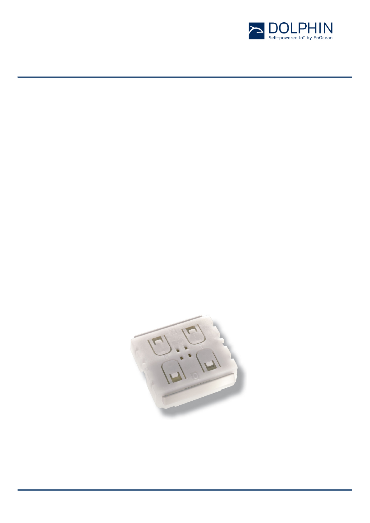
Figure 1 below shows PTM 215B.
Figure 1 – PTM 215B Product Outline
© 2016 EnOcean | www.enocean.com F-710-017, V1.0 PTM 215B User Manual | v0.8 | September 2016 | Page 5/42
Page 6

Antenna
Integrated antenna
Output Power
0 dBm
Communication Ran ge (Gui dance Only )
75 m ideal line of sight / 10 m indoor environment
Communication Standard
BLE Advertising
Radio Frequency (min / max)
2402 MHz / 2480 MHz
Default Radio Channels
BLE CH 37 / 38 / 39 (2402 MHz / 2426 MHz / 2480 MHz)
Advertising Events per action (min / max)
2 / 3
Data Rate and Modulation
1 Mbit/s GFSK
Configuration Interface
NFC Forum Type 2 Tag (ISO/IEC 14443 Part 2 and 3)
Device Identificat io n
Individual 48 Bit Device ID (factory programmed)
Security
AES128 (CBC Mode) with Sequence Code
Power Supply
Integrated Ki netic Ener gy Harvester
Button Inputs
Up to four buttons or two rockers
Module Dimensions
40.0 x 40.0 x 11.2 mm
Module Weight
20 g
Operating Temperature
-25°C ... 65°C
Storage Temperature
-25°C ... 65°C
Humidity
0% to 95% r.h. (non-condensing)
Packaging Unit 100 units
Packaging Metho d Tray / Box (10 units per tray, 10 trays per box)
Type
Ordering Code
Frequency
2.4 GHz (BLE)
USER MANUAL
PTM 215B – 2.4 GHZ Pusbutton Transmitter Module
1.2 Technical data
1.3 Physical dimensions
1.4 Environmental conditions
1.5 Packaging inf o rmation
1.6 Ordering information
PTM 215B S3221-A215
© 2016 EnOcean | www.enocean.com F-710-017, V1.0 PTM 215B User Manual | v0.8 | September 2016 | Page 6/42
Page 7
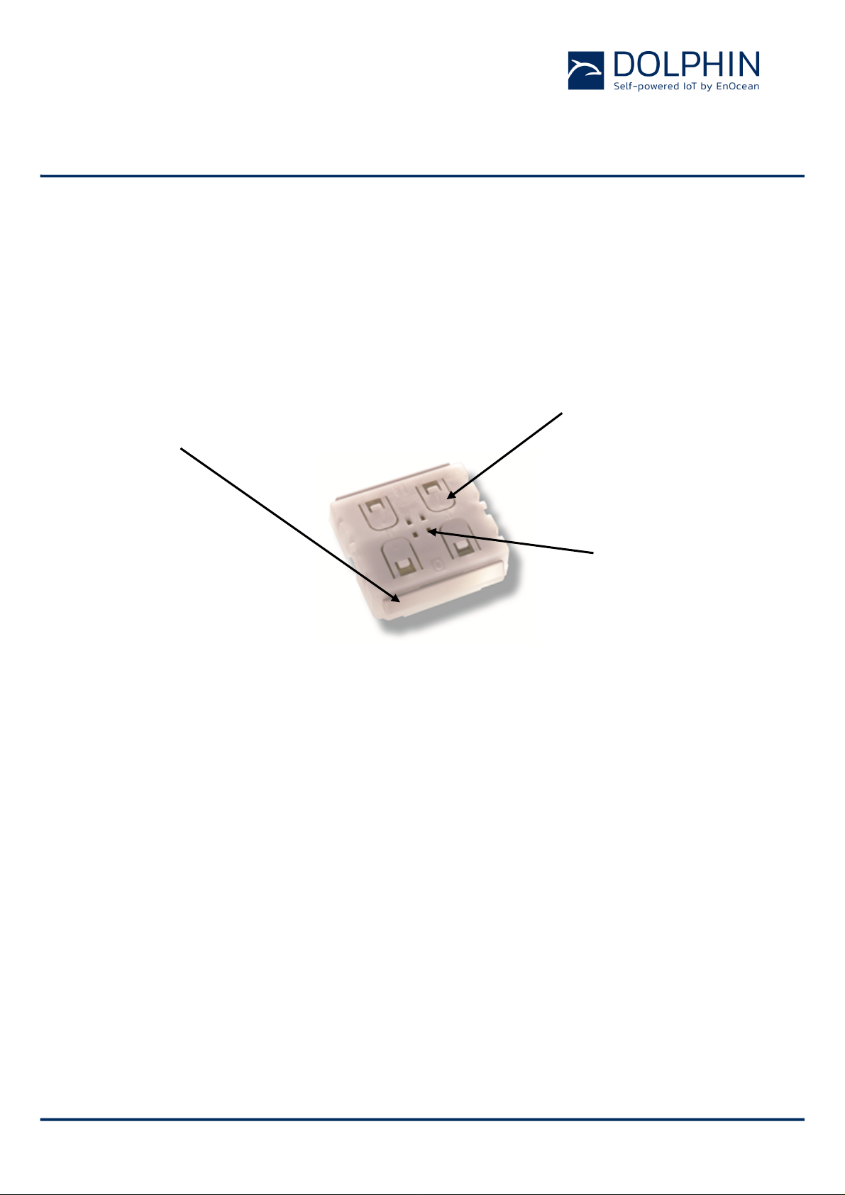
(2) Button contacts
(1) Energy bow
Rotation axis for
USER MANUAL
PTM 215B – 2.4 GHZ Pusbutton Transmitter Module
2 FUNCTIONAL INFORMATION
2.1 PTM 215B D ev ice Overview
The pushbutton transmitter module PTM 215B from EnOcean enables the implementation of
wireles s remote contr ols without batteries. P ower is provided by a built-in electro-dynamic
power generator. PTM 215B device transmits data based on the 2.4GHz BLE standard.
The outer appearance of PTM 215B is s hown on the pictur e be low.
on both device sides
Figure 2 – Electro-dynamic powered pushbutton t ransmitter module PTM 2 15B
for switch rocker
identification
pushbuttons or
switch rocker
2.2 Basic Functionality
PTM 215B devices contain an electro-dynamic energy transducer which is act uat ed by an
energy bow (1). This bow is pushed by an appropriate push button, switch rocker or a similar cons tru ction m ounte d ont o the devic e. An inte rnal s pring will re leas e th e ener gy b ow as
soon as it is not pushed down anymore.
When the energy bow is pushed down, electrical energy is created and an BLE radio telegram is transmitted which identifies the status (pressed or not pressed) of the four button
contacts (2). Releasing the energy bow similarly generates energy which is used to transmit a different radio telegram.
It is therefore possible to distinguish between radio telegrams sent when the energy bar
was pushed and radio telegrams sent when the energy bar was released.
By identifying these different telegrams types and measuring the time between pushing
and releasing of the energy bar, it is possible to distinguish between “Long” and “Short”
button contact presses. This enables simple implementation of applications such as dimming control or blinds control including slat action.
© 2016 EnOcean | www.enocean.com F-710-017, V1.0 PTM 215B User Manual | v0.8 | September 2016 | Page 7/42
Page 8
Processor
Energy
Bow
Powe
Converte
Dat
DC
Pushed
/
Released
Ant
N
S
Processor
Button Contacts
Energy
Bow
Power
Converter
Dat
DC
Push / Release
Detection
Antenna
N S N
S
NFC
RF Transmitter
USER MANUAL
PTM 215B – 2.4 GHZ Pusbutton Transmitter Module
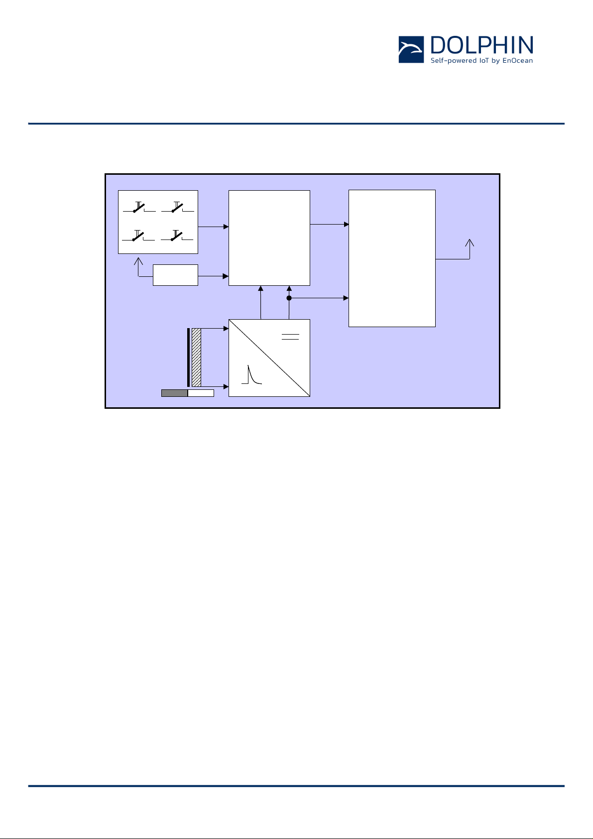
2.3 Block Diagram
Figure 3 – Functional block diagram of PTM 215B
Energy Bow / Power Genera t or
Converts the motion of the energy bow into electr ical energy
Power Converter
Converts the e nergy of the p ower gen erator into a sta ble DC s upply voltage for the device
electronics
Processor
Determines the status of the button contacts and the energy bow, encodes this status into
a data word, generates the proper radio telegram structure and sends it to the radio
transmitter
RF transmitter
Transmits the data in the form of a series of short BLE 2.4 GHz radio telegrams using the
integrated antenna
NFC interface
Allows reading and writing certain product parameters using an NFC compliant reader /
writer supporting NFC Forum Type 2 tags (as specified by ISO/IEC 14443 P art 2 and 3 ).
© 2016 EnOcean | www.enocean.com F-710-017, V1.0 PTM 215B User Manual | v0.8 | September 2016 | Page 8/42
Page 9
USER MANUAL
PTM 215B – 2.4 GHZ Pusbutton Transmitter Module
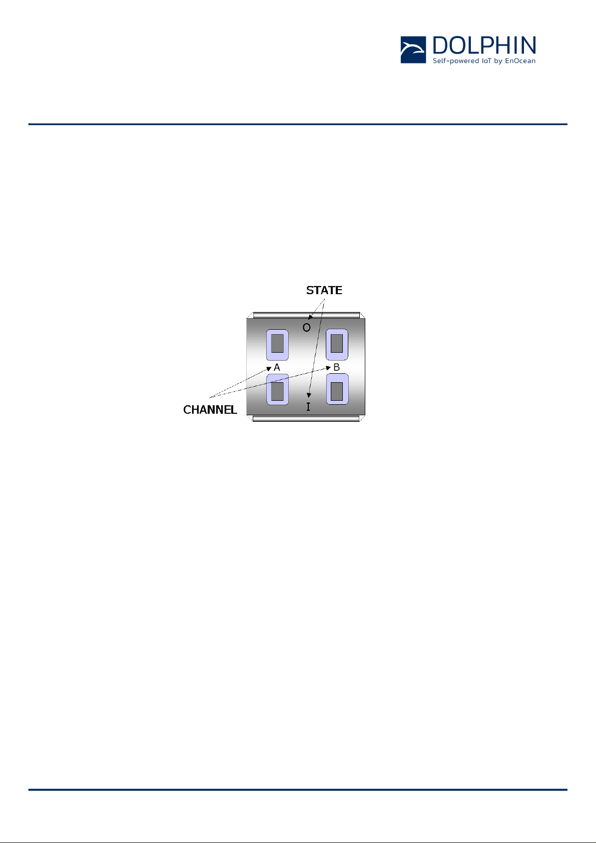
2.4 User Interface
PTM 215B devices provide four button contacts. They are grouped into two channels
(Channel A and Channel B) each containing two button contacts (S tate O and State I) .
The sta te of all four button contacts (pressed or not pressed) is transmitted together with a
unique device identification (48 Bit device ID) whenever the energy bow is pushed or released.
Figure 4 below shows the arrangement of the four button contacts and their designation:
Figure 4 – Button contact designation
© 2016 EnOcean | www.enocean.com F-710-017, V1.0 PTM 215B User Manual | v0.8 | September 2016 | Page 9/42
Page 10
USER MANUAL
PTM 215B – 2.4 GHZ Pusbutton Transmitter Module
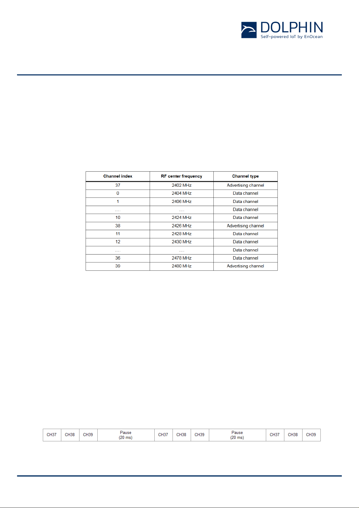
2.5 PTM 215B radio channel parameters
PTM 215B transmits advertising telegrams within the 2.4 GHz radio frequency band
(2402M Hz … 24 8 2M Hz ) using the BLE advertising frame format.
By def ault, PT M 215B w ill us e the three BLE advertisin g channels (Channel 37, 38 and 39)
defined for transmission.
Table 1 below summarizes the radio channel assignment within the BLE standard.
Table 1 – Radio channel paramet ers
The transmission of a radio telegram on all three advertising chan nel s is cal led an Advertising Event. In order to further increase communication reliability, more than one Advertising
Event might be transmitted for an individual radio telegram.
2.5.1 PTM 215B radio transmission sequence
PTM 215B transmits radio telegrams using so-called Advertising Events.
An advertising event is defined as the transmission of the same radio telegram on all se-
lected radio channels (by default this would be on BLE Channel 37, 38 and 39) one after
another with mini mum delay in between.
For reliability reasons, PTM 215B will send several (mi nimu m t wo, m axi mum thr ee) advertising events for each button input. The resulting transmission sequence is shown in Figure
5 below.
Figure 5 – Rad i o t ransmission sequence
© 2016 EnOcean | www.enocean.com F-710-017, V1.0 PTM 215B User Manual | v0.8 | September 2016 | Page 10/42
Page 11
USER MANUAL
PTM 215B – 2.4 GHZ Pusbutton Transmitter Module
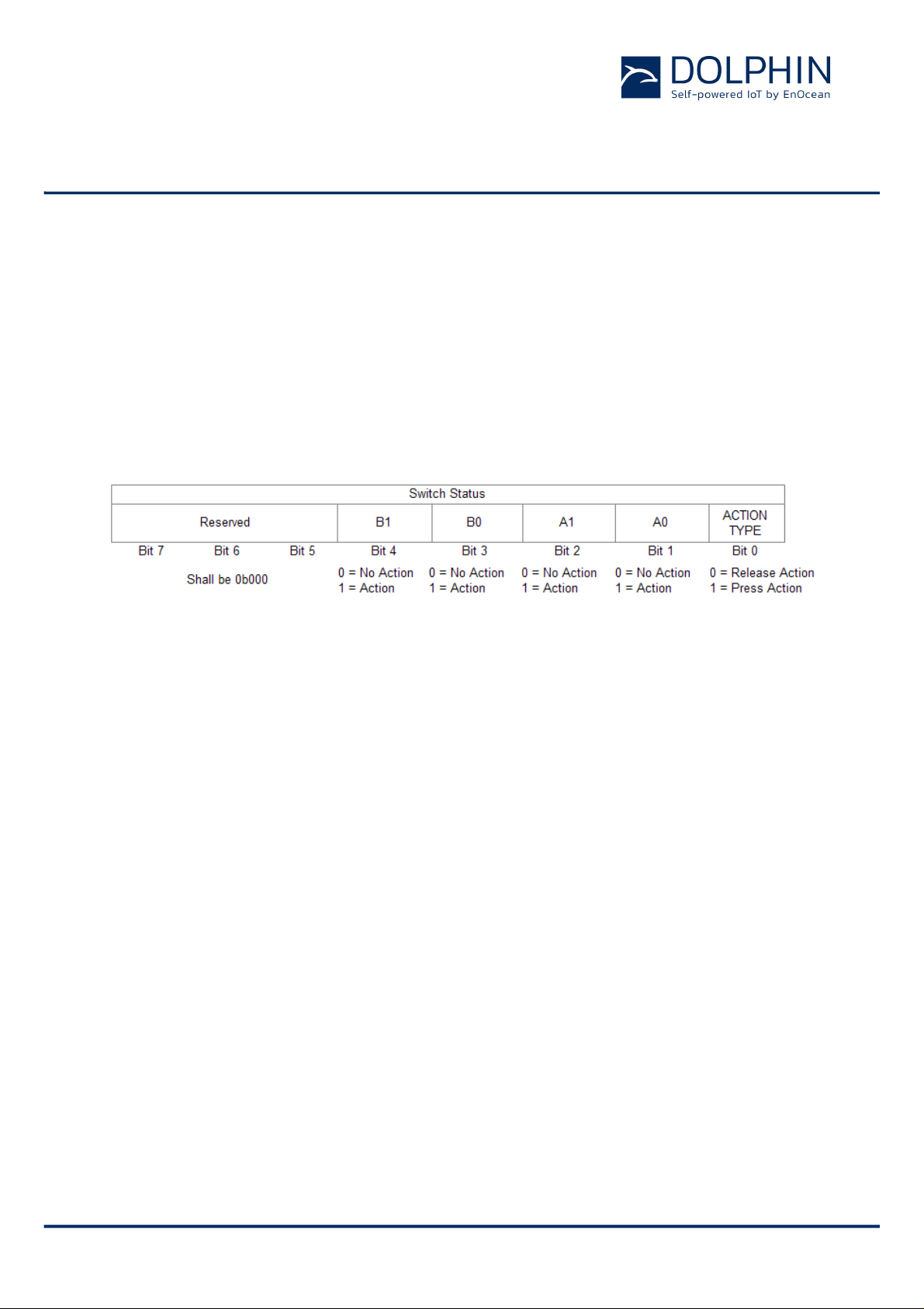
2.6 PTM 215B button action encoding
Figure 6 below shows the button action encoding used by PTM 215B.
In PTM 215B, the type of action (Press Action or Release Action) is indicated by B it 0 (Ener-
gy Bar). If a butt on contact has been actuated during Press Action or Release Action then
this is indicated by the accordi n g status bit set to ‘1’.
Note that all contacts that were pressed during Press Action will be released during Release
Action . The case of cont inuing to h old one (or sev eral) button contacts during Release Action is me chanically not poss ible.
Figure 6 - PTM 215B button action encoding
© 2016 EnOcean | www.enocean.com F-710-017, V1.0 PTM 215B User Manual | v0.8 | September 2016 | Page 11/42
Page 12

USER MANUAL
PTM 215B – 2.4 GHZ Pusbutton Transmitter Module
2.7 PTM 215B comm iss io ning
Commissioning is the process by which PTM 215B is learned into a receiver (actuator, controller, gateway, etc.).
The follow ing two tasks are required in this process:
n Device identification
The receiver needs to know how to uniquely identify this specific PTM 215B device. This
is achieved by using a unique 48 Bit ID (Source Address) for each PTM 215B device as
described in chapter 2.9.4. In addition, up to 4 b yte of Optional Data can be co nfigured
as described in chapter 2.11.4.1
n Security parame ter exchange
The receiver needs to be able to authenticate radio telegrams from PTM 2 15B in order to
ensure that they originate from this specific device and have not been modified as described in chapte r 2.10. This is achieved by exchanging t he 128 Bit random security key
used by PTM 215B to authenticate its radio telegrams.
PTM 215B pr ovides the following option s f or these tasks:
n NFC-based commissioning
The PTM 215B parameters are read by a suitable commissioning tool (e.g. NFC
smartphone) which is alr eady part of the network into which PTM 215B will be com missioned. The commissioning tool then communicates these parameters to the intended
receiver of PTM 215B radio telegrams. NFC-based commissioning is described in chapter
2.11
n Radio-based commissioning
PTM 215B can communicate i ts parameters via special radio telegrams (commissioning
telegrams) to the intended receiver. To do so, PTM 215B can be temporarily placed into
radio-based commissioning mode as described in chapter 2.8.2
n Camera-based commissioning
Each PTM 215 B m odu le contains an automatically readable Data Mat rix Code (DMC)
which identi fies its ID and its security key. This DMC can be read by a by a suitable
commissioning tool (e.g. smartphone) which is already part of the network into which
PTM 215B will be commissioned. The commis sioning tool then c ommunicates these parameters to the intended receiver of PTM 215B radio telegrams. The DMC structure is
described in chapter 3.3.1
© 2016 EnOcean | www.enocean.com F-710-017, V1.0 PTM 215B User Manual | v0.8 | September 2016 | Page 12/42
Page 13

USER MANUAL
PTM 215B – 2.4 GHZ Pusbutton Transmitter Module
2.8 Operation modes
PTM 215B can operate in two modes:
n Data mode
Data mo de is used to transmit data telegrams reporting the status of PTM 215B button
inputs
n Radio-based commis sioning mode
Radio-based commis sioning mode is used to commission (teach-in) PTM 21 5B into a
specific receiver or ne twork by means of a specific commissioning telegram.
This is an alternative for scenarios where NFC commissioning cannot be used.
2.8.1 Data mode
Data mode i s the st andard mode of op eration. In this mod e, PTM 215B will transmit radio
telegr a ms id entifying the status of its four button contacts and the energy bar.
PTM 215B uses the following sequence to identify and transmit button contact status:
1. Determine direction of the energy bar movement (Push Action or Release Action)
2. Read input status of all button contacts
3. Calculate data payload
4. Calculate security signature
5. Format BLE radio telegram
6. Transmit BLE radio telegram as sequence of Ad v e r t ising Events
© 2016 EnOcean | www.enocean.com F-710-017, V1.0 PTM 215B User Manual | v0.8 | September 2016 | Page 13/42
Page 14

USER MANUAL
PTM 215B – 2.4 GHZ Pusbutton Transmitter Module
2.8.2 Radio-based c ommissionin g mode
Radio-based commissioning mode is used to associate PTM 215B with other devices . To do
so, PTM 215B can transmit a dedicated commissioning t elegram (as described in chapter
2.9.6.2) identi fying its relevant parameters. The commissioning telegram will be transmitted on the BLE advertising channels (Channels 37, 38 and 39)
Radio-based commissioning mode is intended for applications where NFC commissioning
(as described in chapter 2.11) cannot be used.
Radio-based commissioning can be disabled by setting the Disable Radio Commissioning
flag in the Configuration register to 0b1 (see chapter 2.11.4.2).
2.8.2.1 Commissioning mode entry
Commissi onin g m ode is ent ered u s ing a spe cia l button contact sequence. This is illustrated
in Figure 7 below.
Figure 7 – Button sequence for commissioning mod e
To enter commissioning mode, start by selecting one button contact of PTM 215B. Any contact of PTM 215B ( A0, A1, B0, B 1) can be used. This contact is referred to as Button_X in
Figure 7 above.
Next, execute the following long-short-long sequence:
1. Press and hold the selected button contact together with the energy bar for more
than 7 seconds before releasing it
2. Press the selected button contact together with the energy bar quickly (hold for less
than 2 seconds)
3. Press and hold the selected button contact together with the energy bar again for
more than 7 seconds before r eleasing it
Upon de tection of this sequence, PTM 215B will enter commissionin g mode if the Disable
Radio Commissioning flag in the configuration register is not set.
© 2016 EnOcean | www.enocean.com F-710-017, V1.0 PTM 215B User Manual | v0.8 | September 2016 | Page 14/42
Page 15

USER MANUAL
PTM 215B – 2.4 GHZ Pusbutton Transmitter Module
2.8.2.2 Commissioning telegram transmission
PTM 215B will transmit a commissioning telegram (as sequence of Advertising Events on
the BLE advertising channels as described in chapter 2.5) upon entering commissioning
mode.
The format of the commissioning telegram is described in chapter 2.9.6.2.
PTM 215B will continue to transmit commissioning telegrams whenever the button used for
entry into commissioning mode (Button_X) is pressed or released again.
2.8.2.3 Exit from commissioning mode
Pressing any key except the button used for entry into commi ssioning mode (Button_X) will
cause PTM 215B to exist commissioning mode an d return to normal data mode.
© 2016 EnOcean | www.enocean.com F-710-017, V1.0 PTM 215B User Manual | v0.8 | September 2016 | Page 15/42
Page 16

USER MANUAL
PTM 215B – 2.4 GHZ Pusbutton Transmitter Module
2.9 BLE frame structure
PTM 215B transmits radio telegrams in the 2.4 GHz band according to BLE frame structure.
For detailed information about the BLE standard, please refer to the applicable specifications.
Figure 8 below summariz es the BLE frame structu re.
Figure 8 – BLE frame structure
The content of these fields is described in more detail below.
2.9.1 Preamble
The BLE Preamble is 1 byte long and identifies the start of the BLE frame. The value of the
BLE Preamble is always set to 0xAA.
2.9.2 Access Address
The 4 by te BLE Access Address identifies t he radio telegram type. For advertising frames,
the value of the Access Ad dress is always set to 0x8E89BED6.
2.9.3 Header
The BLE Header identifies certain radio telegram parameters. Figure 9 below shows the
struc tur e of the BLE header.
Figure 9 – BLE header structure
© 2016 EnOcean | www.enocean.com F-710-017, V1.0 PTM 215B User Manual | v0.8 | September 2016 | Page 16/42
Page 17

USER MANUAL
PTM 215B – 2.4 GHZ Pusbutton Transmitter Module
2.9.4 Source address
The 6 byte BLE Source Address (MAC address) uniquely identifies each PTM 215B product.
PTM 215B su pports two source address modes:
n Static Source Address mode (default)
In this mode, the source address is constant (but can be configured vi a NFC interface)
n Private Resolvable Address mode (NFC configurable)
In this mod e , the sour c e add r e s s c hanges for each tra nsm ission
PTM 215B uses by default the Static Source Address mode. The Private Resolvable Address
mode can be selected by setting the Private Source Address flag in the Configuration register (see chapter 2.11.4.2) to 0b0.
These two address modes are described in the following chapters.
2.9.4.1 Static source ad dress mo d e
By d efa ult , PT M 215 B us e s st at i c source addresses meaning that the source address is constant du ring normal operation . The static source address can be read and configured (written) via NFC as described in chapter 2.11.
The structure of PTM 215B static addresses is as follows:
n The upper 2 bytes of the source address are used to identify the device type and set to
0xE215 for all PTM 215B devices (to designate EnOcean PTM 215 device type).
n The lower 4 bytes are uniquely assigned to each device.
Figure 10 below illustra te s the static address structure used by PTM 215B.
Figure 10 – BLE static source address structure
© 2016 EnOcean | www.enocean.com F-710-017, V1.0 PTM 215B User Manual | v0.8 | September 2016 | Page 17/42
Page 18

USER MANUAL
PTM 215B – 2.4 GHZ Pusbutton Transmitter Module
2.9.4.2 Private resolvable source address mode
For some applications it is desirable to modify (rotate) the source address used by PTM
215B in order to prevent tracking of its radio transmissions. At the same time, each PTM
215B device must rema i n uniq uel y iden t ifiab le by the receiver.
To achieve these goals, PTM 215B can be configured via NFC to use random resolv able private addresses.
Using random resolvable private addresses requires that both PTM 215B and the receiver
both k now a com mon key – the so-called I den tity Re solu ti on K ey (IRK). PTM 215B uses its
device-unique random key as identity resolution key. This key can be configured via NFC
as described in chapter 2.11.
For resolvable private addresses, the 48 bit address field is split into two sub-fields:
n prand
This field contains a random number which always starts (two most significant bits) with
0b10. The prand value is changed for each telegram that is transmitted. Individual advertising events used to transmit one telegram (as described in chapter 2.5.1) use the
same prand value.
n hash
This field contains a verification value (hash) generated from prand using the IRK
The structure of a random resolvable private address is shown in Figure 11 below.
Figure 11 – BLE private r es ol v a b le source address structure
The prand value is encrypted using the IRK. The lowest 24 bit of th e r esu lt ( encrypted value) are then used as hash.
The concatenation of 24 bit prand and 24 bit hash will be transmitted as 48 bit private resolvable source address.
© 2016 EnOcean | www.enocean.com F-710-017, V1.0 PTM 215B User Manual | v0.8 | September 2016 | Page 18/42
Page 19

USER MANUAL
PTM 215B – 2.4 GHZ Pusbutton Transmitter Module
The receiving device maintains a list of IRK for all transmitters that have been commissione d t o w ork with it.
Whenever the receiving device receives a radio telegram with private resolvable source
address (identified by the most significant bits being set to 0b10), it will itself generate a 24
bit hash from th e 24 bit prand sequentially using the IRK of each device that it has been
learne d in to it.
If an IRK matches (i.e. when prand is encoded with this specific IRK then the resu lt matches hash), then the re c eiver has establ ished the ident i ty of the transmitter.
So conceptu ally th e IRK take s the rol e of sou rce ID whil e prand and hash provide a mechanism to select the corre c t IRK amo ng a set of IRK.
This mechanism is ill ustrated in Figure 12 below.
Figure 12 – Resolving p ri v a t e source addresses
2.9.5 Check Sum
The 3 byte BLE Check Sum is used to verify data integrity of received BLE radio telegrams.
It is calculated as CRC (cyclic redundancy check) of the BLE Header, Source Address and
Payload fields.
© 2016 EnOcean | www.enocean.com F-710-017, V1.0 PTM 215B User Manual | v0.8 | September 2016 | Page 19/42
Page 20

USER MANUAL
PTM 215B – 2.4 GHZ Pusbutton Transmitter Module
2.9.6 Payload
The payload st ructure is depending on the telegram type (data telegram or commissioning
telegram).
2.9.6.1 Data Telegram Payload
The payload of data telegrams is 13 … 17 byte s long and consists of the following fields:
n Length (1 byte)
The Length field specifies the combined length of the following fields. The content of th e
field depends on the size of the Optional Data fiel d (which can be 0 / 2 / 2 or 4 byte).
The resulting Length setting would be 12 / 13 / 14 or 16 byte (0x0C / 0x0D / 0x0E / 0x10)
respectively
n Type (1 byte)
The Type field identifies the data type used for this telegram. For PTM 215B data telegrams, this field is always set to 0xFF to des igna te man ufac turer-specific da ta f ield
n Manufacturer ID (2 byte)
The Man u fa cturer ID field is used to identify the manufacturer of BLE devices based on
assigned numbe rs. EnO cean has been assig ned 0x03DA as manufacturer ID code
n Sequence Counter (4 byte)
The Sequence Counter is a monotonously incrementing counter used for security processing. It is initialized to 0 at the time of production and incremented for each telegram
(data telegram or commissioning telegram) sent.
n Switch Status (1 byte)
The Switch Status field reports the button action. The encoding of this field is described
in chapter 2.6.
n Optional Data (0 / 1 / 2 or 4 byte)
PTM 215B provides the option to transmit additional user-defined data within each data
telegram. This data can be used to identify user-specific properties.
The length of the Optional Data field is defined in the Configuration register as described
in chapter 2.11.4.2.
n Security Signature (4 byte)
The Security Signature is used to authenticate PTM 215B radio telegrams as described in
chapter 2.10
Figure 13 below illustrates the data telegram payload.
© 2016 EnOcean | www.enocean.com F-710-017, V1.0 PTM 215B User Manual | v0.8 | September 2016 | Page 20/42
Page 21

USER MANUAL
PTM 215B – 2.4 GHZ Pusbutton Transmitter Module
Figure 13 – Data telegram payload structure
2.9.6.2 Commissio ning Telegra m Pay load
The payload of commissioning telegrams is 31 bytes long and consists of the following
fields:
n Length (1 byte)
The Length field specifies the combined length of the following fields. For PTM 215B
commissioning telegrams, this field is always set to 0x06 (6 byte) for the “Short Name”
field a nd to 0x17 (23 byte) for the “Manufacturer-specific Dat a” field
n Type (1 byte)
The Type field identifies the data type used for this telegram. For PTM 215B commissioning telegrams, this field is set to 0x08 for the “Short Name” fiel d and to 0xFF for the
“Manufacturer-spe c ific Data” fie ld
n Sho rt Name
The Short Name field identifies PTM 215B using the string “P215B”
n Manufacturer ID (2 byte)
The Manufactu rer ID field ca n be used to ident if y the ma nufa ct ure r of BLE dev ice s base d
on assigned numbers. EnOcean has been assigned 0x03DA as manufacturer ID code
n Sequence Counter (4 byte)
The Sequence Counter is a monotonously incrementing counter used for security processing. It is initialized to 0 at the time of production and incremented for each telegram
(data telegram or commissioning telegram) sent.
n Security Key (16 byte)
Each PTM 215B device contains its own 16 byte device-unique random security key
which is generated and programmed during manufacturing. It is transmitted during
commissioning to enable the receiver to authenticate PTM 215B data telegrams
Figure 14 below illustra te s the commissioning telegram payload.
Figure 14 – Commissioning telegram p ayload structure
© 2016 EnOcean | www.enocean.com F-710-017, V1.0 PTM 215B User Manual | v0.8 | September 2016 | Page 21/42
Page 22

USER MANUAL
PTM 215B – 2.4 GHZ Pusbutton Transmitter Module
2.10 Telegram authentication
PTM 215B implements telegram authentication to ensure that only telegrams from senders
using a previously exchanged security key will be accepted. Authentication relies on a 32
bit telegram signature which is calculated as shown in Figure 15 below and exchanged as
part of the ra d io telegram.
Figure 15 – Telegram authentication flow
Sequence counter, s ource address and the remaining telegram data together form the input data for the signature algorithm. This algorithm uses AE S 12 8 e nc ry pt io n base d on the
device-unique random security key to generate a 32 bit signature which will be transmitted
as part of the radio telegram.
The signature is therefore dependent both on the curr ent value of the sequenc e c ounter,
the device source address and the telegram pay load. Changin g any of these three parameters will therefore result in a different signature.
The receiver performs the same signature calculation based on sequence cou nte r, sou rce
address and the remaining telegram data of the received telegram using the security key it
received from PTM 215B during commissioning.
The receiver then compares the signature reported as part of the telegram with the signature it has calc u lated. If these tw o s ignatures matc h then the following statemen ts are
true:
n Sender (PTM 215B) and receiver use the same security key
n The message content (address, sequence counter, data) has not been modified
At this point, the receiver has validated that the message originates f rom a trusted sender
(as identified by its security key) and that its content is valid.
In order to avoid message repl ay (capture and retransmission of a valid message), it is
required that the receiver tracks the val u e of the sequence counter used by PTM 215B and
only accepts messages with higher sequence counter values (i.e. not accept s equal or lower
sequence coun ter va lues for subsequen t te legrams).
© 2016 EnOcean | www.enocean.com F-710-017, V1.0 PTM 215B User Manual | v0.8 | September 2016 | Page 22/42
Page 23

USER MANUAL
PTM 215B – 2.4 GHZ Pusbutton Transmitter Module
2.10.1 Authentication implementation
PTM 215B implements t elegram authenticati on based on AES128 in CCM (Counter with
CBC-MAC) mode as described in IETF RFC 3610.
The 10 Byte CCM Nonce (number used once – unique) initialization value is constructed as
concatenation of 48 bit Device ID and 32 bit Sequence Counter in little endia n format (least
signif icant byte firs t.
Figure 16 below shows the AES128 Nonce.
Figure 16 – AES128 Nonce structure
The AE S128 Nonc e and the 128 bit dev ice-unique security key are then used to calculate a
32 bit signature of the telegram payload shown in Figure 17 below.
Figure 17 – Authenticated payload
The calculated 32 bit signature is then appended to the payload as shown in
Figure 13 in chapter 2.9.6.1.
© 2016 EnOcean | www.enocean.com F-710-017, V1.0 PTM 215B User Manual | v0.8 | September 2016 | Page 23/42
Page 24

USER MANUAL
PTM 215B – 2.4 GHZ Pusbutton Transmitter Module
2.11 NFC interface
PTM 215B implements NFC Forum Type 2 Tag functionality as spe cified in the ISO/IEC
14443 Part 2 an d 3 standard.
This NFC functionality can be u sed to access (read and write) the PTM 215B configuration
memory and thereby configure the device as described in the following chapters.
2.11.1 Configuration memory organization
The P TM 215B configuration memory is divided into the following areas:
n Public data
n Protected data
In addition to that, PTM 215B maintains a private configuration memory region used to
store default parameters and confidential information which is not accessible to the user.
Figure 18 below illustrates the configuration memory organization used by PTM 215B.
Figure 18 – Configuration memory organization
© 2016 EnOcean | www.enocean.com F-710-017, V1.0 PTM 215B User Manual | v0.8 | September 2016 | Page 24/42
Page 25

Area
NFC Page
Total Byte Offse t
Byte 0 (LSB)
Byte 1
Byte 2
Byte 3 (MSB)
Public Memory Area
Public
0x00
0
Public
0x01
4
Public
0x02
8
Public
0x03
12
Public
0x04
16
Public
0x05
20
Public
0x06
24
Public
0x07
28
Public
0x08
32
Static Source Address
Public
0x09
36
Sequence Counter
Protected Memory Area
Protected
0x0A
40
Configuration
Reserved
Protected
0x0B
44
Opt Data 0
Opt Data 1
Opt Data 2
Opt Data 3
Protected
0x0C
48
Protected
0x0D
52
Protected
0x0E
56
Source ID Write
Protected
0x0F
60
Reserved
Protected
0x10
64
Protected
0x11
68
Protected
0x12
72
Protected
0x13
76
Protected
0x14
80
Protected … …
Protected
0x1F
124
Protected
0x20
128
Protected … …
Protected
0x5F
380
Protected
0x60
384
Protected … …
Protected
0xE1
900
USER MANUAL
PTM 215B – 2.4 GHZ Pusbutton Transmitter Module
2.11.2 Memor y Address Map
The NFC-accessible configuration memory is organized in memory pages where each
memory page is 4 byte wide. Each NFC access reads or writes one memory page.
The addresses map of th e confi gur ati on me mory is sh own in Figure 19 bel ow. T he byt e order is little endian, i.e. Byte 0 will be read first and Byte 3 last.
Reserved
Product Name "PTM 215B"
Product ID
Product ID Write
Security Key Write
Reserved
Figure 19 – Configuration memory address map
© 2016 EnOcean | www.enocean.com F-710-017, V1.0 PTM 215B User Manual | v0.8 | September 2016 | Page 25/42
Custom NFC Data
Reserved
Page 26

USER MANUAL
PTM 215B – 2.4 GHZ Pusbutton Transmitter Module
2.11.3 Public data
Public data can be read by any NFC-capable device supporting the ISO/IEC 14443 Part 2
and 3 standard. No specific security measures are used to restrict read acces s to this data.
The follow ing items are located in the public data area:
n PTM 215B Static Source Address (32 Bit, see chapter 2.9.4.1)
n PTM 215B Product Name (this is always “PTM 215B”)
n PTM 215B Product ID (up to 8 characters, to be assigned by the user)
n Telegram sequence counter (initialized to 0 during manufacturing and incremented for
each transmitted te legram)
Changing the Static Source Address and Produc t ID fields is only possible via protected data
access as described below to prevent unauthorized modification.
For security reasons, the telegram sequence counter cannot be w ritt en or reset by any
mechanism.
2.11.4 Protected Data
The follow ing items are located in the protected data area:
n Source Address Write register
n Produc t ID Write register
n Securi ty Key Wr i te register
n Optional Data register
n Configuration register
n Customer Data
© 2016 EnOcean | www.enocean.com F-710-017, V1.0 PTM 215B User Manual | v0.8 | September 2016 | Page 26/42
Page 27

USER MANUAL
PTM 215B – 2.4 GHZ Pusbutton Transmitter Module
2.11.4.1 PIN Code
Protected data access is only possible after unlocking the configuration memory with the
correct 32 bit PIN code.
By default, the protected area is locked and the default pin code for unlocking access is
0x0000E215. This pin code should be changed to a user-defined value as part of an y NFC -
based installation process.
2.11.4.1 Modifying product parameters
Modify ing (writing ) PTM 215B the following product parameters is not directly possible:
n Static Source Address
n Produc t ID
n Security Key
In order to modify these parameters, the user has to write the new value into specific registers (Source Ad dress Write, Product ID Write and Security Key Write) in the protected
data area and set the according Update f lag in the Configuration register.
2.11.4.2 Source Ad d ress Write register
The Source Address Write register is 6 byte wide and can be used to modify the PTM 215B
source address.
In order to d o so, follow thes e s te ps:
1. Write new source address into the Source Address Write register
2. Set the Update Source Address flag in the Configuration register to 0b1
3. Actuate (press and release) PTM 215B
PTM 215B will determine that it should modify the source address based on the setting of
the Update Source Address flag and copy t he va lue of the So urce Address Wri te reg ister to
the Source Address register.
After successful executio n, PTM 215B will clear the Updat e So urce Address flag to 0b0.
© 2016 EnOcean | www.enocean.com F-710-017, V1.0 PTM 215B User Manual | v0.8 | September 2016 | Page 27/42
Page 28

USER MANUAL
PTM 215B – 2.4 GHZ Pusbutton Transmitter Module
2.11.4.3 Security Key Write register
The Security Key Write register is 16 byte wide and contains the device-unique random
security key.
The factory programmed key can be replaced with a user defined key by following these
steps:
1. Write new security key into the Security Key Write register
Note tha t for security reasons, setting the Sec urity Key to the fo llo wing values is not
possible:
• 0x00000000000000000000000000000000
• 0xFFFFFFFFFFFFFFFFFFFFFFFFFFFFFFFF
If the Security Key Wri te register is set to one of these values then no update of the
Security Key will occur.
2. Set the Update Security Key flag in the Configuration register to 0b1
3. If the key should be write-only (not readable a fte r the key update) then set the Private Security Key flag i n th e Co n f iguration register to 0b1
4. Actuate (press and release) PTM 215B
PTM 215B will determine tha t it s ho u ld m o d if y t he security key based on the s etting of the
Update Security Key flag and copy the value of the Security Key Write register to the Security Key register in private mem ory.
After successful executio n, PTM 215B will clear the Updat e Security Key flag to 0b0.
If the Private Key flag in the Configuration register is set to 0b0 then the content of the Se-
curity Key Write register will be maintained at its current value. This addresses use ca ses
where the security key shall be readable for users having the correct PIN c ode.
If the Private Key flag in the Configuration register is set to 0b1 then the content of the Security Key Write register will be cleared to 0x00000000000000000000000000000000 afte r suc-
cessful execution. This addresses use cases where the security key shall never be readable
(even for users having the correct PIN code). The Security Key Write register will maintain
this value of 0x00000000000000000000000000000000 even if the Private Key flag in the Con-
figura t io n register is subseq ue n tly cleared to 0b0. This ensures that it is not possible to
read a security key whi ch was written with t he If the Private Key flag in the Configuration
register being set.
Note tha t it is not possible to read the current securit y key via NFC if the Security Key Write
register has been accidentally overwritten or cleared via NFC write. In this case it is necessary to write a n ew security key (as described above) or to reset the device to its default
security key by means of a factory reset.
The protected memo ry is designed to support 1000 modi fications of the security key .
© 2016 EnOcean | www.enocean.com F-710-017, V1.0 PTM 215B User Manual | v0.8 | September 2016 | Page 28/42
Page 29

USER MANUAL
PTM 215B – 2.4 GHZ Pusbutton Transmitter Module
2.11.4.4 Product ID Write register
The Product ID register is 8 byte wide and can be used to specify a publicly-accessible parameter (e.g. a u ser-specific ID or name).
In order to d o so, follow thes e s te ps:
1. Write new product ID (using ASCII encoding) into the Product ID Write register.
2. Set the Update Product ID flag in the Configuration register to 0b1
3. Actuate (press and release) PTM 215B
PTM 215B will determine that it should update the shor t na m e based on the sett ing of the
Update Product ID flag and copy the value of the Product ID Write regis te r to the Product
ID register.
After successful executio n, PTM 215B will clear the Updat e Product ID flag to 0b0.
2.11.4.1 Optional Data register
The Optional Data regi ster can be used to specify up to 4 byte of custom data that will be
transmitted as part of each data telegram. This optional data can store user-specific or application-specific information.
The size of the Optional Data field is specified in the Configuration register and can be 0
byte (not present, default), 1 byte, 2 byte or 4 byte.
If the size of the Optional Data field is set to a non-zero value in the Configuration register
then PTM 215B will read the corresponding amount of data from the Optional Data register
beginning with the least sig nificant byte (Byte 0) .
Note tha t using the Optional Data feature requires add itional ener g y for the radio telegram
transmission and might therefore reduce the total number of redundant telegrams which
are transmitted.
© 2016 EnOcean | www.enocean.com F-710-017, V1.0 PTM 215B User Manual | v0.8 | September 2016 | Page 29/42
Page 30

USER MANUAL
PTM 215B – 2.4 GHZ Pusbutton Transmitter Module
2.11.4.2 Configuration register
The Configuration register is 1 byte wide and contains configuration flags. Figure 20 below
shows the structure of the Configuration register.
Figure 20 – C onfiguration register st ructure
2.11.4.3 Customer Data
PTM 215B allocates 64 pages (256 byte) for customer data that can be read and written via
the NFC interface i n protected mode.
The main intention is to enable storing OEM-specific information such as product type, revision, date code or similar. There is however no restriction (other than the maximum size of
256 byte) on the type of content that can be stored in this memory region.
PTM 215B will not access or modify this memory region.
Users should keep in mind that the content of this memory region will not be affected by a
factory reset. This means that after a factory reset, the content of this memory region can
be read using the default PIN code. This regi on should therefore not be used to store sensitive data.
© 2016 EnOcean | www.enocean.com F-710-017, V1.0 PTM 215B User Manual | v0.8 | September 2016 | Page 30/42
Page 31

USER MANUAL
PTM 215B – 2.4 GHZ Pusbutton Transmitter Module
2.11.5 Private Data
The priva te data area stores the following items:
n Security Key
n Default settings
The content of the private data area is not externally accessible.
2.11.5.1 Security Key
The Security Key fie ld co n tai ns the 12 8-B it ke y used for authenticating PTM 215B telegrams
and for resolving private source addresses.
2.11.5.2 Default Settings
The Default Settings field contains a backup of the following PTM 215B factory settings:
n Sou rce Address
n Security Key
n NFC PIN Code
These default settings can be restored by means of a factory reset as described in chapter
2.12 below.
© 2016 EnOcean | www.enocean.com F-710-017, V1.0 PTM 215B User Manual | v0.8 | September 2016 | Page 31/42
Page 32

USER MANUAL
PTM 215B – 2.4 GHZ Pusbutton Transmitter Module
2.12 Factory Reset
PTM 215B can be reset to its default set tings by means of a factory reset.
This ensures that PTM 215B can be reset to a known configuration in case the PIN for the
NFC access has been lost or NFC access is not possible for other reasons
In order to execute such fact ory reset, the rocker(s) and the switch housing have to be
removed from the PTM 215B module. Then, all four button contacts (A0, A1, B0 and B1)
have to be pressed at the same time while the energy bow is pressed down.
The energy bow must then be held at the down position for at least 10 seconds before being released. The button contacts A0, A1, B0 and B1 can be released at any time after
pressing the energy bow down, i.e. it is no requirement to hold them as well for at least 10
seconds.
Upon detecting this input, PTM 215B will restore the default settings of the following i tems:
n Sou rce Address
n Security Key and Secu ri ty Key Wr i te register
Both registers will b e restored to the value of the factory-programme d se cu rity key
n NFC PIN Code
After such factory reset, Source Address and Security Key will again match the content of
the DMC code on the unit label as described in chapter 3.3.
In addition, PTM 215B will reset the following register:
n Configuration register (to 0x00)
© 2016 EnOcean | www.enocean.com F-710-017, V1.0 PTM 215B User Manual | v0.8 | September 2016 | Page 32/42
Page 33

Energy bow travel / o
N
Restoring force at energy bow
Number of operations at 25°C typ. 100.000 actuations tested according to VDE 0632 / EN 60669
Cover material Hostaform (POM)
Energy bow material PBT (50% GV)
USER MANUAL
PTM 215B – 2.4 GHZ Pusbutton Transmitter Module
3 Device Integration
PTM 215B is designed for integration into button or rocker based switches. It implements
the established PTM 2xx mechanical form factor and can therefore be used with a wide variety of existing designs.
3.1 Mechanical Interface Characteristics
perating force 1.8 mm / typ. 10
Only one of the two energ y b ows may b e actuated at the same time!
At room temperature
typ. 0.7 N
Minimum restoring f orce of 0.5 N is required for correct o p e rati on
3.2 Mechanical Interface Drawings
Figure 21 – P TM 215B, tilted view (including rocker catwalks)
© 2016 EnOcean | www.enocean.com F-710-017, V1.0 PTM 215B User Manual | v0.8 | September 2016 | Page 33/42
Page 34

USER MANUAL
PTM 215B – 2.4 GHZ Pusbutton Transmitter Module
1) these catwalks are not needed when using one single rocker only 2) dimensions of rocker part
Figure 22 – P TM 215B, top view (note cut A, B and C marking)
© 2016 EnOcean | www.enocean.com F-710-017, V1.0 PTM 215B User Manual | v0.8 | September 2016 | Page 34/42
Page 35

USER MANUAL
PTM 215B – 2.4 GHZ Pusbutton Transmitter Module
Figure 23 – P TM 215B, cut A
2) dimensions of rocker part
Figure 24 – P TM 215B, cut B and C
© 2016 EnOcean | www.enocean.com F-710-017, V1.0 PTM 215B User Manual | v0.8 | September 2016 | Page 35/42
Page 36

USER MANUAL
PTM 215B – 2.4 GHZ Pusbutton Transmitter Module
Hatched areas: support planes
Figure 25 – P TM 215B rear view
© 2016 EnOcean | www.enocean.com F-710-017, V1.0 PTM 215B User Manual | v0.8 | September 2016 | Page 36/42
Page 37

If th e rocker i s not m ounted on the r otation axis of PTM 215B several tolerances
have to be considered! The measure from support plane to top of the energy bow
The movement of the energy bow mu st not be limited by mounted rockers!
Catwalks of the switch rocker must not exert continuous forces on the button con-
USER MANUAL
PTM 215B – 2.4 GHZ Pusbutton Transmitter Module
2) dimensions of rocker part
is 7.70 mm +/- 0.3 mm!
tacts!
Figure 26 – P TM 215B, side view
© 2016 EnOcean | www.enocean.com F-710-017, V1.0 PTM 215B User Manual | v0.8 | September 2016 | Page 37/42
Page 38

USER MANUAL
PTM 215B – 2.4 GHZ Pusbutton Transmitter Module
3.3 Device Label
Each PTM 215ZE module c o n ta i ns a device label as shown in Figure 27 below.
Figure 27 – P TM 215B d ev ice label
This device label identifies the following parameters in writing:
n Manufacturing date (WEEK / YEAR)
n Sou rce Address (SOURCE_ID)
Note that the device label also contains a DMC code in the lower right corner as described
below.
© 2016 EnOcean | www.enocean.com F-710-017, V1.0 PTM 215B User Manual | v0.8 | September 2016 | Page 38/42
Page 39

USER MANUAL
PTM 215B – 2.4 GHZ Pusbutton Transmitter Module
3.3.1 Device DMC
Each PTM 215B module contains a data matrix code (DMC) on the lower right hand side of
the device label which can be used to automaticall y scan device parameters.
The DMC uses the ECC200 standard to encode up to 52 characters. The content of the DMC
uses the following forma t:
<PRODUCT_NAME>ID<SOURCE_ID>OOB<DEVICE_KEY>
This identifies the following para meters:
n Product name
n 32 Bit Sourc e Address (different for each device, excludes “E215” Prefix)
n 128 Bit device-unique random security key (different for each device)
One possible DMC readin g could for instance be:
PTM215BID01500100OOB0123456789ABCDEF0123456789ABCDEF
This wou ld identify the fol lowing parameters:
n Product name = PTM 215B
n Source Address = E21501500100
n Device-unique random security key = 0123456789ABCDEF0123456789ABCDEF
© 2016 EnOcean | www.enocean.com F-710-017, V1.0 PTM 215B User Manual | v0.8 | September 2016 | Page 39/42
Page 40

USER MANUAL
PTM 215B – 2.4 GHZ Pusbutton Transmitter Module
4 APPLICATION INFORMATION
4.1 Transmission rang e
The main factors that influence the system transmission range are:
- Type and location of the antennas of receiver and transmitter
- Type of t errain and degre e of ob struction of the link path
- Sources of interference affecting the receiver
- “Dead spots” caused by signal reflections from nearby conductive objects.
Since the expect ed transmission range strongly depends on thi s system conditions, range
tests should always be performed to determine the reliably achievable range under the given conditions.
The follow ing figures should be treat e d as a rough guide only :
- Line-of-sight connections
Typically 10 m range in corridors, up to 30 m in hal ls
- Plasterboard walls / dry wood
Typically 10 m range, through max. 2 walls
- Ferro c oncrete walls / ce ilings
Typically 5 m range, t hrough max. 1 cei li ng (depending on thickness)
- Fire-safety walls, elevator shafts, st aircases and similar areas sh ould be considered
as shielded
The angle at which the transmitted signal hits the wall is very important. The effective wall
thickness – and with it the signal attenuation – varies according to this angle. Signals
should be transmitted as directly as possible through the wall. Wall niches should be avoided.
Other factors restricting transmission range include:
- Switch mounting on metal surfaces (up to 30 % loss of transmission range)
- Hollow lightweight wal ls filled with insulating wool on metal foil
- False ceilings with pan els of metal or ca rbon fibre
- Lead glass or glass with metal coating, steel furniture
The distance between the receiver and other transmitting devices such as computers, audio
and video equipment that also emit high-fr e quency signa ls s hould be at least 0. 5 m .
© 2016 EnOcean | www.enocean.com F-710-017, V1.0 PTM 215B User Manual | v0.8 | September 2016 | Page 40/42
Page 41

USER MANUAL
PTM 215B – 2.4 GHZ Pusbutton Transmitter Module
5 REGULATORY INFORMATION
PTM 215B has been certified according to FCC, IC and CE regulations.
Changes or modifications not expressly approved by EnOcean could void the user's authority to oper ate the equipm ent.
5.1 FCC (United States) Certificate
<To be inserted>
5.1.1 FCC (United States) Regulatory Statement
This device complies with part 15 of the FCC Rules. Operation is subject to the following
two condi tions:
(1) this device may not cause harmful interference, and
(2) this device must accept any interference received, including interference that may
cause undesired operation.
© 2016 EnOcean | www.enocean.com F-710-017, V1.0 PTM 215B User Manual | v0.8 | September 2016 | Page 41/42
Page 42

USER MANUAL
PTM 215B – 2.4 GHZ Pusbutton Transmitter Module
5.2 IC (Industry Canada) Certificate
<To be inserted>
5.2.1 IC (Industry Canada) Regulatory Statement
This device complies with Industry Canada licence-exempt RSS standard(s).
Operation is subject to the following two conditions:
(1) this device may not cause interference, an d
(2) this device must accept any interference, including interference that may cause unde-
sired operation of th e device.
Le présent appareil est conforme aux CNR d'Industrie Canada applicables aux appareils
radio exempts de licence.
L'exp lo i ta tion est autor is ée aux deux conditions suivantes :
(1) l'appareil ne doit pas produire de brouillage, et
(2) l'utilisateur de l'appareil doit accepter tout brouillage radioélectrique subi, même si le
broui lla ge est susceptible d'en comprom e t tre le fonctionnement.”
© 2016 EnOcean | www.enocean.com F-710-017, V1.0 PTM 215B User Manual | v0.8 | September 2016 | Page 42/42
 Loading...