

Page 1

USER MANUAL V0.9
EnOcean GmbH
Kolpingring 18a
82041 Oberhaching
Germany
Phone +49.89.67 34 689-0
Fax +49.89.67 34 689-50
[email protected]
www.enocean.com
Subject to modifications
PTM 210 / 210C step EA User Manual V0.9
October 18, 2011 4:33 PM
Page 1/17
Pushbutton Transmitter Device
PTM 210 / 210C
October 18, 2011
Patent protected:
US 6,747,573
US 7,019,241
Further patents pending
Page 2

USER MANUAL V0.9
EnOcean GmbH
Kolpingring 18a
82041 Oberhaching
Germany
Phone +49.89.67 34 689-0
Fax +49.89.67 34 689-50
[email protected]
www.enocean.com
Subject to modifications
PTM 210 / 210C step EA User Manual V0.9
October 18, 2011 4:33 PM
Page 2/17
PTM 210 / 210C STEP EA
No
Major Changes
0.95
New EEP naming included (EEP 2.1)
REVISION HISTORY
The following major modifications and improvements have been made to the first version of
this document:
Published by EnOcean GmbH, Kolpingring 18a, 82041 Oberhaching, Germany
www.enocean.com, [email protected], phone ++49 (89) 6734 6890
© EnOcean GmbH
All Rights Reserved
Important!
This information describes the type of component and shall not be considered as assured
characteristics. No responsibility is assumed for possible omissions or inaccuracies. Circuitry
and specifications are subject to change without notice. For the latest product specifications, refer to the EnOcean website: http://www.enocean.com.
As far as patents or other rights of third parties are concerned, liability is only assumed for
modules, not for the described applications, processes and circuits.
EnOcean does not assume responsibility for use of modules described and limits its liability
to the replacement of modules determined to be defective due to workmanship. Devices or
systems containing RF components must meet the essential requirements of the local legal
authorities.
The modules must not be used in any relation with equipment that supports, directly or
indirectly, human health or life or with applications that can result in danger for people,
animals or real value.
Components of the modules are considered and should be disposed of as hazardous waste.
Local government regulations are to be observed.
Packing: Please use the recycling operators known to you. By agreement we will take packing material back if it is sorted. You must bear the costs of transport. For packing material
that is returned to us unsorted or that we are not obliged to accept, we shall have to invoice you for any costs incurred.
Page 3

USER MANUAL V0.9
EnOcean GmbH
Kolpingring 18a
82041 Oberhaching
Germany
Phone +49.89.67 34 689-0
Fax +49.89.67 34 689-50
[email protected]
www.enocean.com
Subject to modifications
PTM 210 / 210C step EA User Manual V0.9
October 18, 2011 4:33 PM
Page 3/17
PTM 210 / 210C STEP EA
TABLE OF CONTENT
1 GENERAL DESCRIPTION .................................................................................... 4
1.1 Basic Functionality ........................................................................................... 4
1.2 Typical Applications .......................................................................................... 5
1.3 Technical Data ................................................................................................. 5
1.4 Mechanical Interface ......................................................................................... 5
1.5 Environmental Conditions ................................................................................ 10
1.6 Ordering Information ...................................................................................... 10
2 FUNCTIONAL DESCRIPTION ............................................................................. 10
2.1 Block Diagram ............................................................................................... 10
2.2 Contact Nipples Designation ............................................................................ 11
2.3 Transmission timing ....................................................................................... 12
3 APPLICATIONS INFORMATION ......................................................................... 13
3.1 Laying the antenna (PTM 210C only) ................................................................ 13
3.2 Construction of application specific Switch Rockers ............................................. 14
3.3 Device Mounting ............................................................................................ 14
3.4 Transmission Range ....................................................................................... 15
4 AGENCY APPROVALS ...................................................................................... 16
4.1 CE Approval (PTM 210 only) ............................................................................ 16
4.2 FCC/IC Approval (PTM 210C only) .................................................................... 16
4.3 Japanese Type Approval (PTM 210C only) ......................................................... 17
Page 4
USER MANUAL V0.9
EnOcean GmbH
Kolpingring 18a
82041 Oberhaching
Germany
Phone +49.89.67 34 689-0
Fax +49.89.67 34 689-50
[email protected]
www.enocean.com
Subject to modifications
PTM 210 / 210C step EA User Manual V0.9
October 18, 2011 4:33 PM
Page 4/17
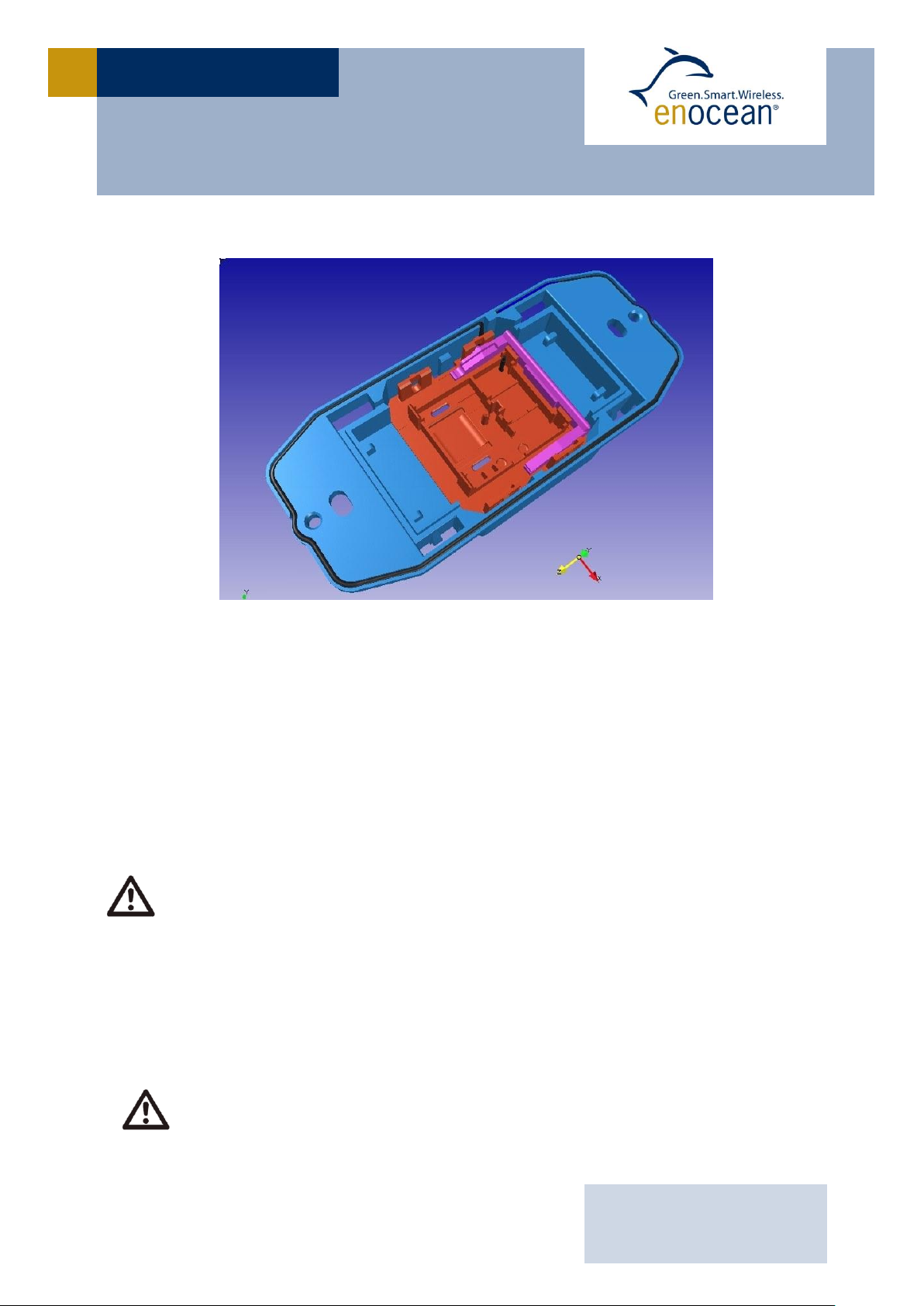
PTM 210 / 210C STEP EA
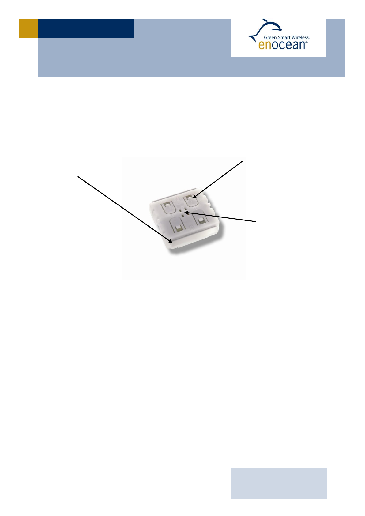
(2) Contact nipples
for switch rocker
identification
(1) Energy bow
on both device sides
Rotation axis for
pushbuttons or
switch rocker
1 GENERAL DESCRIPTION
The radio transmitter device PTM 210 / PTM 210C from EnOcean enables the implementation of wireless remote controls without batteries. Power is provided by a built-in electrodynamic power generator. The PTM 210 / PTM 210C device serves the 868 MHz / 315 MHz
air interface protocol of EnOcean.
Electro-dynamic powered radio transmitter device PTM 210
1.1 Basic Functionality
A common electro-dynamic energy transducer is actuated by a bow (1), which can be
pushed from outside the device by an appropriate push button or switch rocker. When the
energy bow is pushed down, electrical energy is created and an RF telegram is transmitted
including a 32-bit device ID. Releasing the energy bow generates different telegram data,
so every PTM telegram contains the information that the bow was pressed or released.
“Long” or “Short” push button operation (the time between pushing and releasing the
pushbutton) can be easily detected by the receiver. By doing that, applications such as
dimming control or blinds control including slat action are simple to implement.
In addition, the PTM telegram transmits the operating status of the contact nipples (2)
when pressing the bow. This enables the identification of up to 2 appropriate switch rockers
or up to 4 pushbuttons.
Page 5

USER MANUAL V0.9
EnOcean GmbH
Kolpingring 18a
82041 Oberhaching
Germany
Phone +49.89.67 34 689-0
Fax +49.89.67 34 689-50
[email protected]
www.enocean.com
Subject to modifications
PTM 210 / 210C step EA User Manual V0.9
October 18, 2011 4:33 PM
Page 5/17
PTM 210 / 210C STEP EA
Power supply power generation by rocker operating (Electrodynamic Power Generator)
Antenna PTM 210C external whip antenna 26.8 cm, ø1.3
0.1
mm
Antenna PTM 210 internal PCB antenna
Frequency 315.0 MHz (PTM 210C) / 868.3 MHz (PTM 210)
Data rate / Modulation type 125 kbps / ASK
Channels 2 with 4 action states each (upper/lower pushbutton is pressed/released)
EnOcean Equipment Profile supported EEP F6-02-xx, F6-03-xx, F6-04-xx
Transmission range typ. 300 m free field, typ. 30 m indoor
Telegram packet length (sub telegram) 0.7 ms +/- 5%
Number of channels 2 channels with action states each
(upper/lower contact nipple is pressed/released)
Device-identifier individual 32-bit ID (factory programmed)
No. of (redundant) packets PTM 210: 3 / PTM 210C: 3–5 (depending on residual energy)
Module dimensions (inclusive rotation axis and energy bow) 40.0 x 40.0 x 11.2 mm
Device weight 20 g ± 1 g
Energy bow travel / operating force 1.8 mm / approx. 7 N *)
*) at room temperature, only one energy bow may be actuated at the same time!
Restoring force at energy bow 0.5 N to 4 N
For the correct function of the application, the specified minimal restoring force of 0.5 N must be considered!
Number of operations typ. 50.000 actuations tested according to VDE 0632 / EN 60669
Cover material Hostaform (POM)
Energy bow material PBT (50% GV)
1.2 Typical Applications
Building installation
Industrial automation
Consumer electronics
Key applications are wall-mounted flat rocker switches with 1 or 2 rockers, as well as handheld remote controls with up to 4 single pushbuttons. Because the RF transmitters are selfpowered (no batteries), maintenance-free RF systems are possible.
1.3 Technical Data
1.4 Mechanical Interface
Page 6
USER MANUAL V0.9
EnOcean GmbH
Kolpingring 18a
82041 Oberhaching
Germany
Phone +49.89.67 34 689-0
Fax +49.89.67 34 689-50
[email protected]
www.enocean.com
Subject to modifications
PTM 210 / 210C step EA User Manual V0.9
October 18, 2011 4:33 PM
Page 6/17
PTM 210 / 210C STEP EA
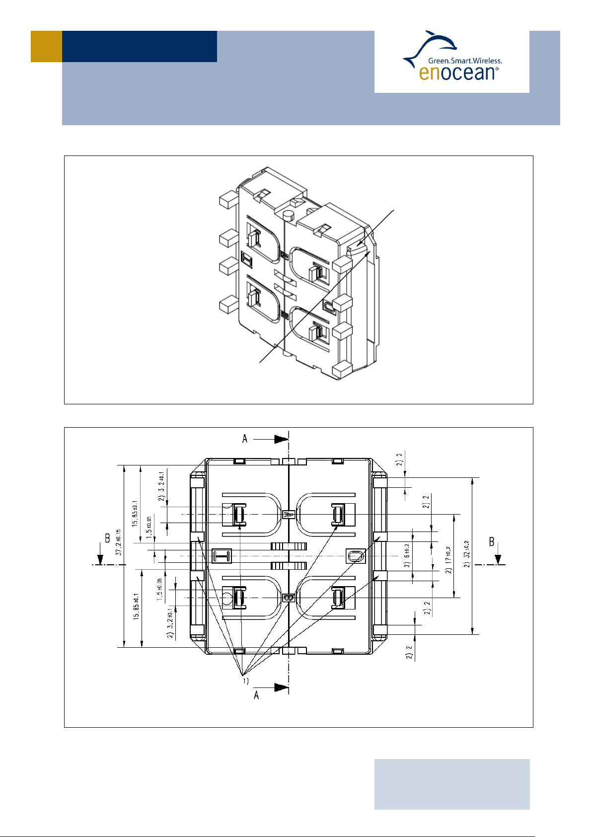
Energy Bow
Stopper
PTM 210 without antenna, tilted view (including rocker catwalks)
1) this catwalks are not needed when using one single rocker only 2) dimensions of rocker part
PTM 210 without antenna, top view (note cut A, B and C marking)
Page 7
USER MANUAL V0.9
EnOcean GmbH
Kolpingring 18a
82041 Oberhaching
Germany
Phone +49.89.67 34 689-0
Fax +49.89.67 34 689-50
[email protected]
www.enocean.com
Subject to modifications
PTM 210 / 210C step EA User Manual V0.9
October 18, 2011 4:33 PM
Page 7/17
PTM 210 / 210C STEP EA
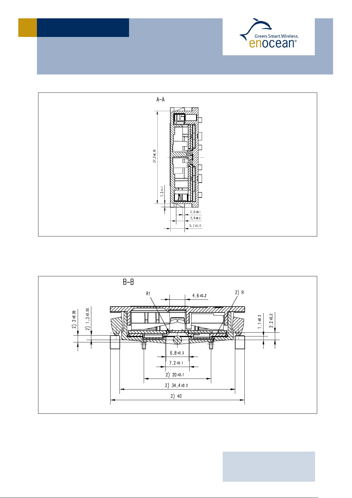
PTM 210 without antenna, cut A
2) dimensions of rocker part
PTM 210 without antenna, cut B and C
Page 8
USER MANUAL V0.9
EnOcean GmbH
Kolpingring 18a
82041 Oberhaching
Germany
Phone +49.89.67 34 689-0
Fax +49.89.67 34 689-50
[email protected]
www.enocean.com
Subject to modifications
PTM 210 / 210C step EA User Manual V0.9
October 18, 2011 4:33 PM
Page 8/17
PTM 210 / 210C STEP EA
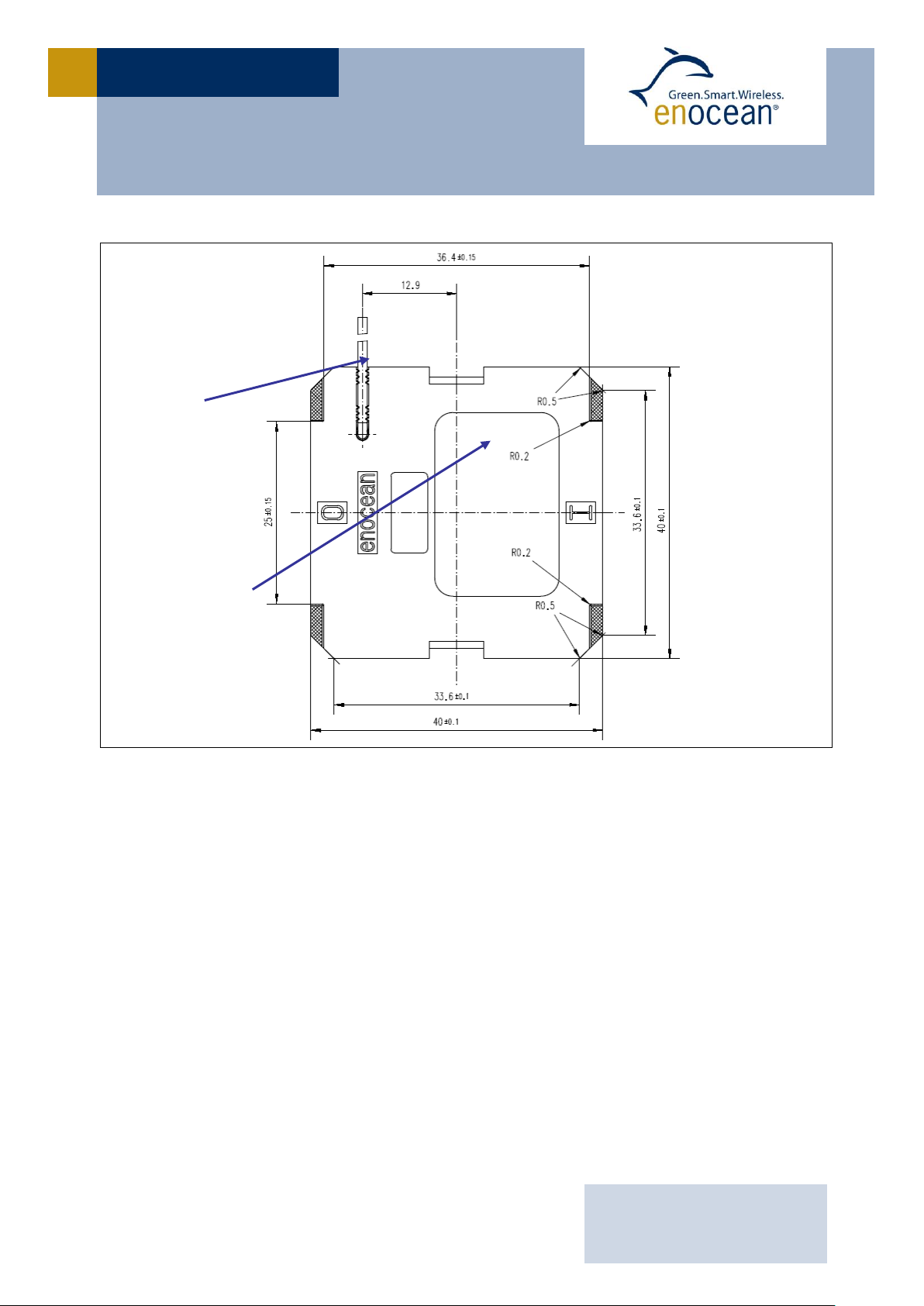
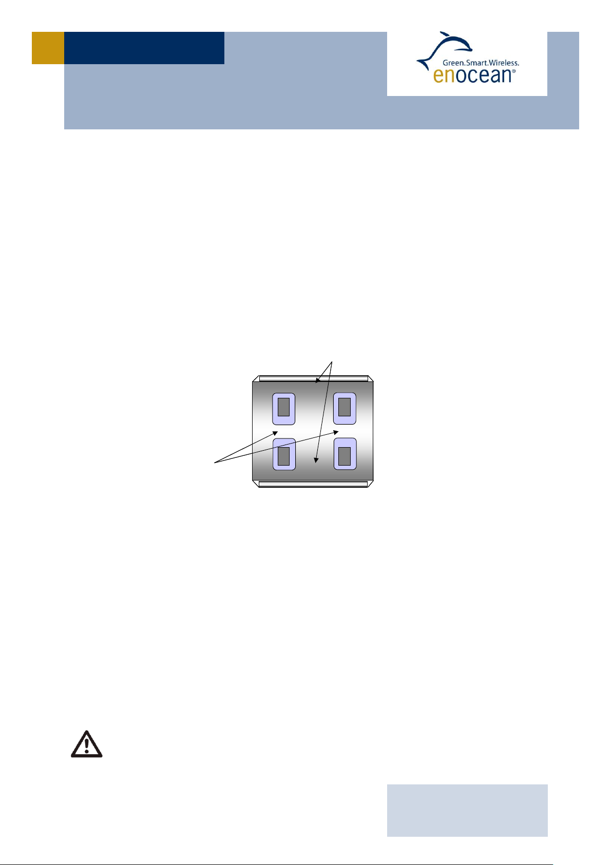
labeling area
antenna
Hatched areas: support planes
PTM 210C with antenna (PTM 210 provides internal antenna), rear view
Page 9
USER MANUAL V0.9
EnOcean GmbH
Kolpingring 18a
82041 Oberhaching
Germany
Phone +49.89.67 34 689-0
Fax +49.89.67 34 689-50
[email protected]
www.enocean.com
Subject to modifications
PTM 210 / 210C step EA User Manual V0.9
October 18, 2011 4:33 PM
Page 9/17
PTM 210 / 210C STEP EA
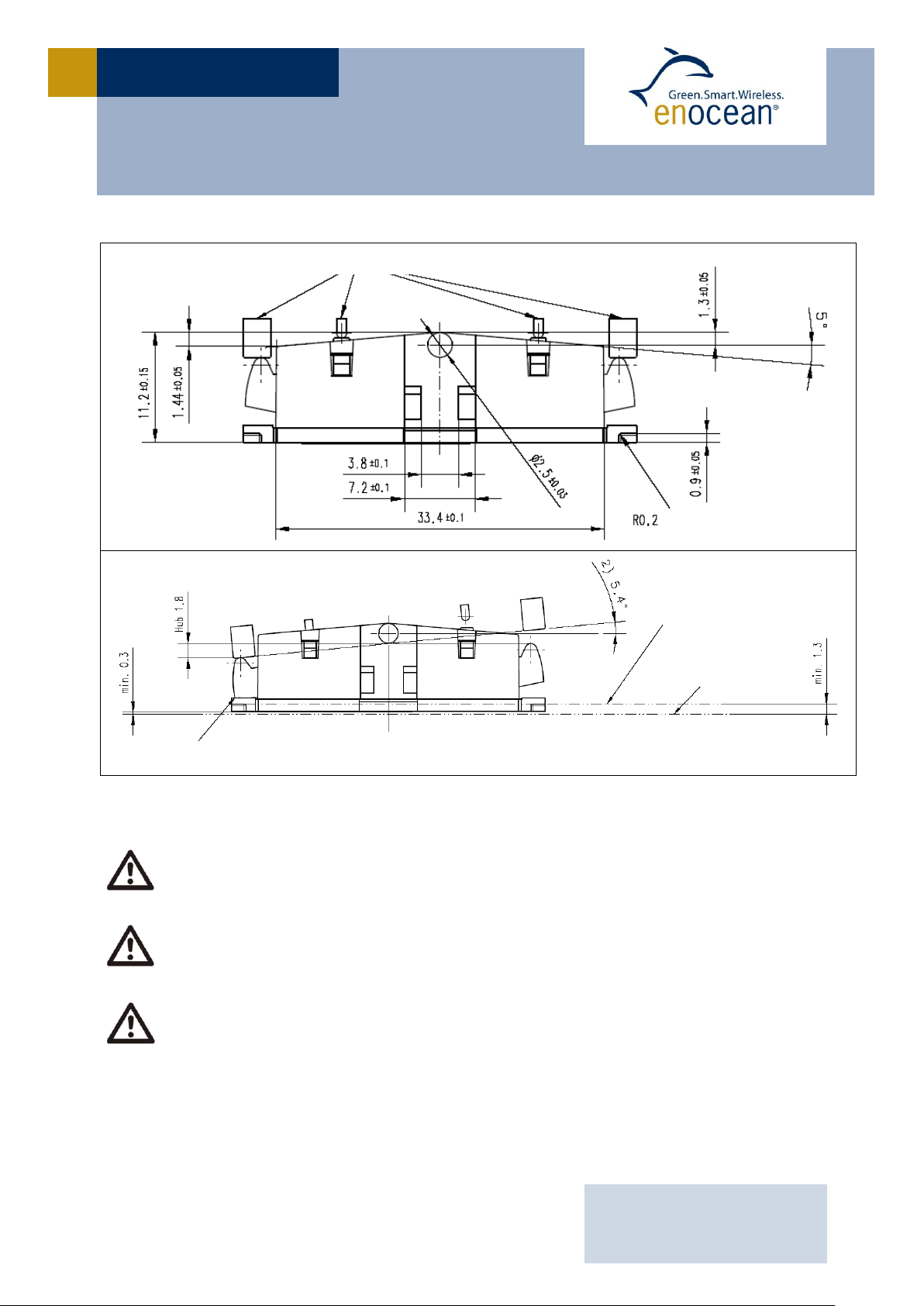
If the rocker is not mounted on the rotation axis of PTM 210 several tolerances
have to be considered!
The measure from support plane to top of the energy bow is 7.70 mm +/- 0.3
mm!
The movement of the energy bow must not be limited by mounted rockers!
Catwalks of switch rocker must not exert continuous forces on contact nipples!
catwalks of switch rocker
rocker tilted to 5.4 degrees (corresponds to 1.8 mm energy bow travel)
press bow to stopper
support plane
mounting plane
rotary
2) dimensions of rocker part
PTM 210 without antenna, side view
Page 10
USER MANUAL V0.9
EnOcean GmbH
Kolpingring 18a
82041 Oberhaching
Germany
Phone +49.89.67 34 689-0
Fax +49.89.67 34 689-50
[email protected]
www.enocean.com
Subject to modifications
PTM 210 / 210C step EA User Manual V0.9
October 18, 2011 4:33 PM
Page 10/17
PTM 210 / 210C STEP EA
Operating temperature -25 °C up to +65 °C
Storage temperature -25 °C up to +65 °C
Humidity 0% to 95% r.h.
Type
Ordering Code
PTM 210
S3001-A210
PTM 210C
S3031-A211
Processor
HF
Contact Nipples
Energy
Bow
Power
Converter
Data
DC Power
Pushed/Released
Ant
N
S
Processor
HF
Contact Nipples
Energy
Bow
Power
Converter
Data
DC Power
Pushed/Released
Ant
NSN
S
1.5 Environmental Conditions
1.6 Ordering Information
2 FUNCTIONAL DESCRIPTION
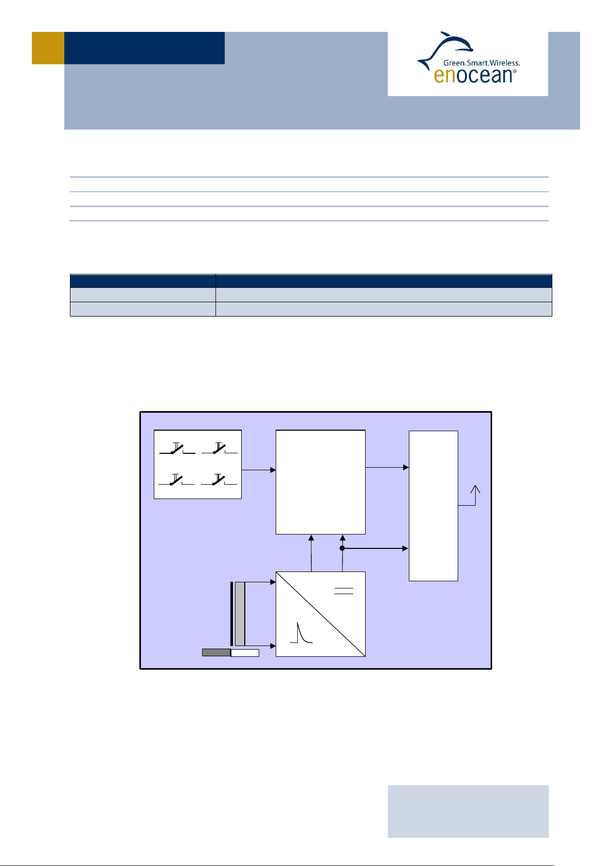
2.1 Block Diagram
Block diagram of PTM 210
Energy Bow / Power Generator
Converts pressure on the energy bow into electrical energy.
Power Converter
Electronic converter unit for generating the device DC power supply
Page 11
USER MANUAL V0.9
EnOcean GmbH
Kolpingring 18a
82041 Oberhaching
Germany
Phone +49.89.67 34 689-0
Fax +49.89.67 34 689-50
[email protected]
www.enocean.com
Subject to modifications
PTM 210 / 210C step EA User Manual V0.9
October 18, 2011 4:33 PM
Page 11/17
PTM 210 / 210C STEP EA
Due to the mechanical hysteresis of the energy bow, in most rocker switch device
implementations, pressing the rocker sends an N-message and releasing the rocker sends a U-message!
O
I
BA
CHANNEL
STATE
O
I
BA
CHANNEL
STATE
Processor
Converts the contact nipples’ status and pushed/released data from the power generator
into a reliable and energy-efficient serial telegram structure.
HF transmitter
Sends the data in the form of a series of short radio signals.
2.2 Contact Nipples Designation
With 4 contact nipples, the PTM 210 offers 2 channels with 4 action states each (upper/lower nipple is pressed/released when activating the energy bow). The nipples’ designation is as follows:
Contact nipple designation
Radio signals of the PTM 210 device are event-controlled (energy bow is pressed/released)
with contact nipple code (channel/state) and unique device identification (fixed 32-bit ID).
When operating more than one nipple at the same time, note that PTM 210 sends multiplebutton code combinations:
N-message: One or two contact nipples have been pressed when activating the energy
generator Message with nipple code and pressed/released event status of the energy
bow is sent.
U-message: No contact nipple was pressed when activating the energy generator, or 3
or 4 nipples have been pressed Message with pressed/released event status of the
energy bow is sent and the information if either none or more than two nipples have
been pressed. Note that it can’t be differentiated if 3 or if 4 nipples have been pressed.
Page 12

USER MANUAL V0.9
EnOcean GmbH
Kolpingring 18a
82041 Oberhaching
Germany
Phone +49.89.67 34 689-0
Fax +49.89.67 34 689-50
[email protected]
www.enocean.com
Subject to modifications
PTM 210 / 210C step EA User Manual V0.9
October 18, 2011 4:33 PM
Page 12/17
PTM 210 / 210C STEP EA
2.3 Transmission timing
The transmission timing of the radio device PTM 210C has been developed to avoid possible
collisions with data packages of other EnOcean transmitters as well as disturbances from
the environment.
With each transmission cycle, at least three identical subtelegrams are transmitted. The
transmission of a subtelegram lasts approximately 0.7 ms. To optimize data security, each
telegram is repeated twice within about 40 ms, whereas the delay between the second and
the third transmission burst is effected at random.
If some residual energy is available after transmission of three subtelegrams, up to 2 further subtelegrams are sent (PTM 210C only).
Page 13
USER MANUAL V0.9
EnOcean GmbH
Kolpingring 18a
82041 Oberhaching
Germany
Phone +49.89.67 34 689-0
Fax +49.89.67 34 689-50
[email protected]
www.enocean.com
Subject to modifications
PTM 210 / 210C step EA User Manual V0.9
October 18, 2011 4:33 PM
Page 13/17
PTM 210 / 210C STEP EA
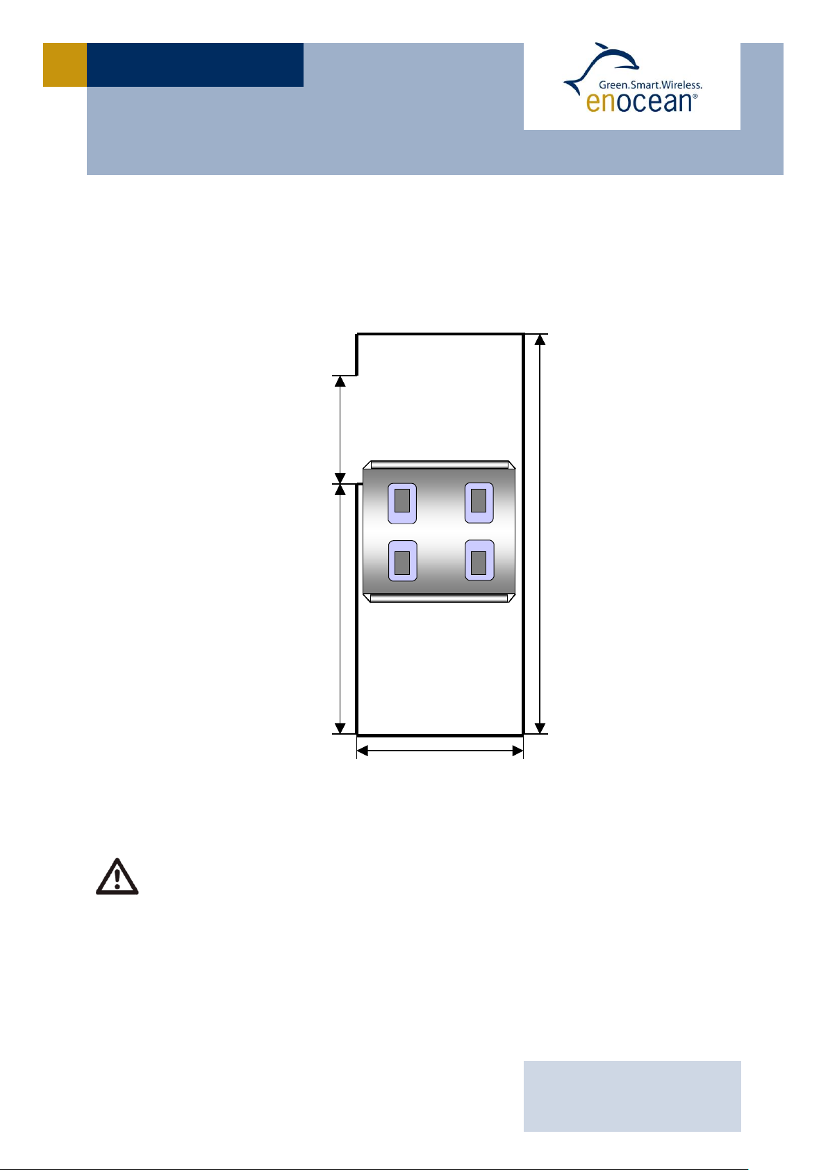
The distance between antenna foot point and antenna end must be > 25 mm
The antenna area should be maximized
The antenna should be placed at the same height above the ground plane as
the rotation axis for the switch rocker (see example below)
O
I
BA
O
I
BA
~ 102mm
~ 42mm
~ 63mm > 25mm
O
I
BA
O
I
BA
O
I
BA
O
I
BA
~ 102mm
~ 42mm
~ 63mm > 25mm
3 APPLICATIONS INFORMATION
3.1 Laying the antenna (PTM 210C only)
For best performance the antenna cable should be layed as shown in the figure below.
Laying the 315 MHz whip antenna
Page 14
USER MANUAL V0.9
EnOcean GmbH
Kolpingring 18a
82041 Oberhaching
Germany
Phone +49.89.67 34 689-0
Fax +49.89.67 34 689-50
[email protected]
www.enocean.com
Subject to modifications
PTM 210 / 210C step EA User Manual V0.9
October 18, 2011 4:33 PM
Page 14/17
PTM 210 / 210C STEP EA
Please note that the rockers should be of nonmetal for best transmission range!
Please also avoid plastic materials with conducting ingredients like graphite!
Mounting the module back side on metal surfaces directly or mounting the module
into metal frames can lead to up to typical 30% loss of transmission range within
a building.
Example of a well suited antenna
3.2 Construction of application specific Switch Rockers
For CAD system development support, 3D construction data is available from EnOcean (IGS
data). Using this data, the mechanical interface is fixed, and the shape and surface of the
rocker(s) can be changed according to requirements. Recommendation for suitable rocker
material is polycarbonate (buckling resistant and wear-proof material). It is recommended
to apply teflon varnish in the areas of actuation.
3.3 Device Mounting
For mounting the PTM 210 device into an application specific case, the package outline
drawings of the device are roughly dimensioned in chapter 1.4. If more detailed dimensioning data device case is necessary, 3D construction data is available from EnOcean (IGS
data).
Page 15

USER MANUAL V0.9
EnOcean GmbH
Kolpingring 18a
82041 Oberhaching
Germany
Phone +49.89.67 34 689-0
Fax +49.89.67 34 689-50
[email protected]
www.enocean.com
Subject to modifications
PTM 210 / 210C step EA User Manual V0.9
October 18, 2011 4:33 PM
Page 15/17
PTM 210 / 210C STEP EA
3.4 Transmission Range
The main factors that influence the system transmission range are type and location of the
antennas of the receiver and the transmitter, type of terrain and degree of obstruction of
the link path, sources of interference affecting the receiver, and “dead” spots caused by
signal reflections from nearby conductive objects. Since the expected transmission range
strongly depends on this system conditions, range tests should categorically be performed
before notification of a particular range that will be attainable by a certain application.
The following figures for expected transmission range are considered by using a PTM, a
STM or a TCM radio transmitter device and the TCM radio receiver device with preinstalled
whip antenna and may be used as a rough guide only:
Line-of-sight connections: Typically 30 m range in corridors, up to 100 m in halls
Plasterboard walls / dry wood: Typically 30 m range, through max. 5 walls
Line-of-sight connections: Typically 30 m range in corridors, up to 100 m in halls
Ferro concrete walls / ceilings: Typically 10 m range, through max. 1 ceiling
Fire-safety walls, elevator shafts, staircases and supply areas should be considered as
screening.
The angle at which the transmitted signal hits the wall is very important. The effective wall
thickness – and with it the signal attenuation – varies according to this angle. Signals
should be transmitted as directly as possible through the wall. Wall niches should be
avoided. Other factors restricting transmission range:
Switch mounted on metal surfaces (up to 30% loss of transmission range)
Hollow lightweight walls filled with insulating wool on metal foil
False ceilings with panels of metal or carbon fibre
Lead glass or glass with metal coating, steel furniture
The distance between EnOcean receivers and other transmitting devices such as computers, audio and video equipment that also emit high-frequency signals should be at least
0.5 m
A summarized application note to determine the transmission range within buildings is
available as download from www.enocean.com.
Page 16

USER MANUAL V0.9
EnOcean GmbH
Kolpingring 18a
82041 Oberhaching
Germany
Phone +49.89.67 34 689-0
Fax +49.89.67 34 689-50
[email protected]
www.enocean.com
Subject to modifications
PTM 210 / 210C step EA User Manual V0.9
October 18, 2011 4:33 PM
Page 16/17
PTM 210 / 210C STEP EA
Trade Name: PTM 210C
Model No: PTM 210C
This device complies with Part 15 of the FCC Rules and with RSS-210 of Industry Canada.
Operation is subject to the following two conditions. (1) this device may not cause harmful
interference, and (2) this device must accept any interference received, including interfe-
rence that may cause undesired operation.
FCC ID: SZV-PTM211C
IC: 5713A-PTM211C
4 AGENCY APPROVALS
4.1 CE Approval (PTM 210 only)
The devices bear the EC conformity marking CE and conform to the R&TTE EU-directive on
radio equipment. The assembly conforms to the European and national requirements of
electromagnetic compatibility. The conformity has been proven and the corresponding documentation has been deposited at EnOcean. The PTM devices can be operated without
notification and free of charge in the area of the European Union, and in Switzerland. The
following provisos apply:
EnOcean RF devices must not be modified or used outside their specification limits.
EnOcean RF devices may only be used to transfer digital or digitized data. Analog speech
and/or music are not permitted.
The final product incorporating EnOcean RF devices must itself meet the essential re-
quirement of the R&TTE Directive and a CE marking must be affixed on the final product
and on the sales packaging each. Operating instructions containing a Declaration of Conformity has to be attached.
If transmitters are used according to the regulations of the 868.3 MHz band, a so-called
“Duty Cycle” of 1% per hour for each transmitter must not be exceeded. Permanent transmitters such as radio earphones are not allowed. For conventional applications, i t must be
ensured that the PTM 210 radio device is not operated more than 6000 times within one
hour (one operation: energy bow is pressed and released). Within this calculation, the extraordinary short telegram length is considered including three subtelegrams. Also a tolerance of 5% in the telegram length is included.
4.2 FCC/IC Approval (PTM 210C only)
This device complies with Part 15 of the FCC Rules and with RSS-210 of Industry Canada. If
this device is operated in compliance with the following requirements it can be operated
without notification and free of charge in the area of the United States of America and in
Canada. Operation is subject to the following two conditions:
(1) this device may not cause harmful interference, and
(2) this device must accept any interference received, including interference that
may cause undesired operation.
Page 17

USER MANUAL V0.9
EnOcean GmbH
Kolpingring 18a
82041 Oberhaching
Germany
Phone +49.89.67 34 689-0
Fax +49.89.67 34 689-50
[email protected]
www.enocean.com
Subject to modifications
PTM 210 / 210C step EA User Manual V0.9
October 18, 2011 4:33 PM
Page 17/17
PTM 210 / 210C STEP EA
Changes or modifications made to this equipment not expressly approved by EnOcean may void the FCC authorization to operate this equipment.
4.3 Japanese Type Approval (PTM 210C only)
PTM 210C complies with the Japanese radio law. It carries the following marking on the
back side label (MIC marking):
+++ in preparation +++
If the certification label cannot be recognized from outside (e.g. installation in a host) appropriate information must be referenced in the user manual.
 Loading...