

EnOcean PTM210U User Manual

USER MANUAL
EnOcean GmbH
Kolpingring 18a
82041 Oberhaching
Germany
Phone +49.89.67 34 689-0
Fax +49.89.67 34 689-50
info@enocean.com
www.enocean.com
Subject to modifications
PTM 210 / PTM 215 / PTM 21U User Manual
January 2013
OctoberPage 1/19
Pushbutton Transmitter Device
PTM 210 / PTM 215 / PTM 210 U
January 10, 2013
Patent protected:
US 6,747,573
US 7,019,241
Further patents pending

USER MANUAL
EnOcean GmbH
Kolpingring 18a
82041 Oberhaching
Germany
Phone +49.89.67 34 689-0
Fax +49.89.67 34 689-50
info@enocean.com
www.enocean.com
Subject to modifications
PTM 210 / PTM 215 / PTM 21U User Manual
January 2012
Page 2/19
PTM 210 / PTM 215 / PTM 210 U
No
Major Changes
1
Updated operating force to typ. 8 N
2
Merged PTM 210, PTM 215 and PTM 210U into one user manual
REVISION HISTORY
The following major modifications and improvements have been made to the first version of
this document:
Published by EnOcean GmbH, Kolpingring 18a, 82041 Oberhaching, Germany
www.enocean.com, info@enocean.com, phone ++49 (89) 6734 6890
© EnOcean GmbH
All Rights Reserved
Important!
This information describes the type of component and shall not be considered as assured
characteristics. No responsibility is assumed for possible omissions or inaccuracies. Circuitry
and specifications are subject to change without notice. For the latest product specifications, refer to the EnOcean website: http://www.enocean.com.
As far as patents or other rights of third parties are concerned, liability is only assumed for
devices, not for the described applications, processes and circuits.
EnOcean does not assume responsibility for use of devices described and limits its liability
to the replacement of devices determined to be defective due to workmanship. Devices or
systems containing RF components must meet the essential requirements of the local legal
authorities.
The devices must not be used in any relation with equipment that supports, directly or indirectly, human health or life or with applications that can result in danger for people, animals or real value.
Components of the devices are considered and should be disposed of as hazardous waste.
Local government regulations are to be observed.
Packing: Please use the recycling operators known to you. By agreement we will take packing material back if it is sorted. You must bear the costs of transport. For packing material
that is returned to us unsorted or that we are not obliged to accept, we shall have to invoice you for any costs incurred.

USER MANUAL
EnOcean GmbH
Kolpingring 18a
82041 Oberhaching
Germany
Phone +49.89.67 34 689-0
Fax +49.89.67 34 689-50
info@enocean.com
www.enocean.com
Subject to modifications
PTM 210 / PTM 215 / PTM 21U User Manual
January 2012
Page 3/19
PTM 210 / PTM 215 / PTM 210 U
TABLE OF CONTENT
1 GENERAL DESCRIPTION .................................................................................... 4
1.1 Basic Functionality ........................................................................................... 4
1.2 Typical Applications .......................................................................................... 5
1.3 Technical Data ................................................................................................. 5
1.4 Mechanical Interface ......................................................................................... 6
1.5 Environmental Conditions ................................................................................ 11
1.6 Ordering Information ...................................................................................... 11
2 FUNCTIONAL DESCRIPTION ............................................................................. 12
2.1 Block Diagram ............................................................................................... 12
2.2 Contact Nipples Designation ............................................................................ 13
2.3 Operating modes ........................................................................................... 13
2.3.1 Normal mode (PTM 210, PTM 210U, PTM 215) ................................................ 13
2.3.2 Secure mode (PTM 215)............................................................................... 14
2.3.3 Switching between modes ............................................................................ 15
3 APPLICATIONS INFORMATION ......................................................................... 16
3.1 Construction of application specific Switch Rockers ............................................. 16
3.2 Device Mounting ............................................................................................ 16
3.3 Transmission Range ....................................................................................... 17
4 AGENCY APPROVALS ...................................................................................... 18
4.1 PTM 210 and PTM 215 CE Approval .................................................................. 18
4.2 FCC and Industry Canada Regulatory Statements ............................................... 19
USER MANUAL
EnOcean GmbH
Kolpingring 18a
82041 Oberhaching
Germany
Phone +49.89.67 34 689-0
Fax +49.89.67 34 689-50
info@enocean.com
www.enocean.com
Subject to modifications
PTM 210 / PTM 215 / PTM 21U User Manual
January 2012
Page 4/19
PTM 210 / PTM 215 / PTM 210 U
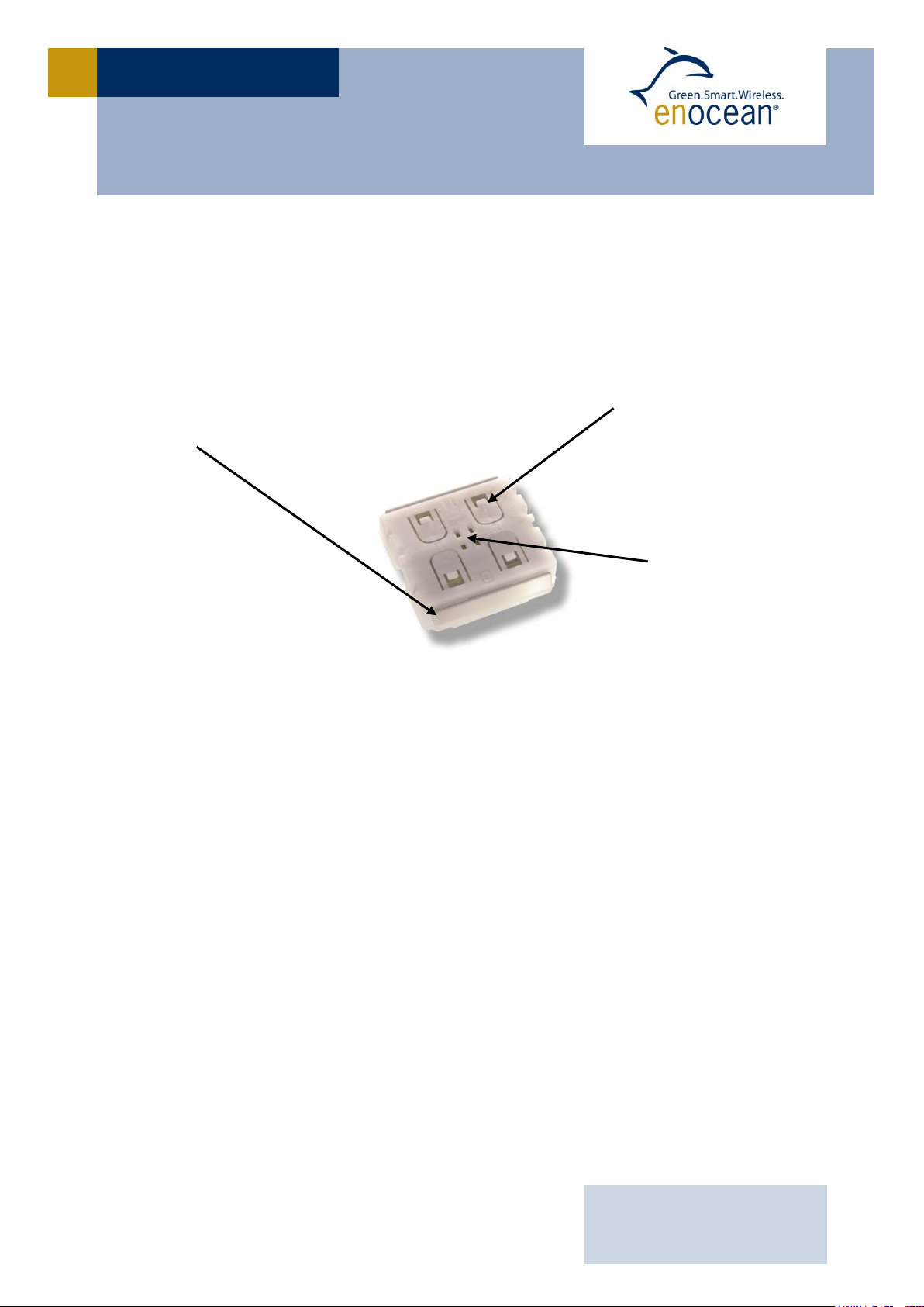
(2) Contact nipples
for switch rocker
identification
(1) Energy bow
on both device sides
Rotation axis for
pushbuttons or
switch rocker
1 GENERAL DESCRIPTION
The radio transmitter device PTM 21x from EnOcean enables the implementation of wireless
remote controls without batteries. Power is provided by a built-in electro-dynamic power
generator. The PTM 21x device serves the 868 MHz and 902 MHz radio interface protocol of
EnOcean.
Electro-dynamic powered radio transmitter device PTM 21x
Following variants are available:
PTM 210 868,300 MHz
PTM 215 868,300 MHz with encryption
PTM 210U 902,875 MHz
1.1 Basic Functionality
A common electro-dynamic energy transducer is actuated by a bow (1), which can be
pushed from outside the device by an appropriate push button or switch rocker. When the
energy bow is pushed down, electrical energy is created and an RF telegram is transmitted
including a 32-bit device ID. Releasing the energy bow generates different telegram data,
so every PTM telegram contains the information that the bow was pressed or released.
“Long” or “Short” push button operation (the time between pushing and releasing the
pushbutton) can be easily detected by the receiver. By doing that, applications such as
dimming control or blinds control including slat action are simple to implement.

USER MANUAL
EnOcean GmbH
Kolpingring 18a
82041 Oberhaching
Germany
Phone +49.89.67 34 689-0
Fax +49.89.67 34 689-50
info@enocean.com
www.enocean.com
Subject to modifications
PTM 210 / PTM 215 / PTM 21U User Manual
January 2012
Page 5/19
PTM 210 / PTM 215 / PTM 210 U
Power supply power generation by rocker operating,
electro-dynamic power generator
Antenna internal PCB antenna
Frequency PTM 210: 868.300 MHz (ASK)*
PTM 215: 868,300 MHz (ASK)*
PTM 210U: 902,875 MHz (FSK)
Data rate 125 kbps
Channels 2 with 4 action states each
upper/lower pushbutton is pressed/released
EnOcean Equipment Profile supported EEP F6-02-xx, F6-04-xx
Security mode rolling code with AES128 (PTM 215 only)
Transmission range typ. 300 m free field, typ. 30 m indoor
Device-identifier individual 32-bit ID (factory programmed)
In addition, the PTM telegram transmits the operating status of the contact nipples (2)
when pressing the bow. This enables the identification of up to 2 appropriate switch rockers
or up to 4 pushbuttons.
PTM 215 supports 2 operating modes. A normal mode and a secure mode with additional
rolling code mechanism which allows to prevent replay attacks in sensible applications.
1.2 Typical Applications
Building installation
Industrial automation
Consumer electronics
Key applications are wall-mounted flat rocker switches with 1 or 2 rockers, as well as
handheld remote controls with up to 4 single pushbuttons. Because the RF transmitters are
self-powered (no batteries), maintenance-free RF systems are possible.
1.3 Technical Data
*) According the international standard for energy harvesting wireless radio protocol for self-powered applications:
ISO/IEC 14543-3-10

USER MANUAL
EnOcean GmbH
Kolpingring 18a
82041 Oberhaching
Germany
Phone +49.89.67 34 689-0
Fax +49.89.67 34 689-50
info@enocean.com
www.enocean.com
Subject to modifications
PTM 210 / PTM 215 / PTM 21U User Manual
January 2012
Page 6/19
PTM 210 / PTM 215 / PTM 210 U
Device dimensions (inclusive rotation axis and energy bow) 40.0 x 40.0 x 11.2 mm
Device weight 20 g ± 1 g
Energy bow travel / operating force 1.8 mm / typ. 8 N
*) at room temperature, only one energy bow may be actuated at the same time!
Restoring force at energy bow typ. 0.7 N to 4 N
For the correct function of the application, the specified minimal restoring force of 0.5 N must be considered!
Number of operations at 25°C typ. 100.000 actuations tested according to VDE 0632 / EN 60669
Cover material Hostaform (POM)
Energy bow material PBT (50% GV)
1.4 Mechanical Interface
 Loading...