

EnOcean PTM200C User Manual

Pushbutton Transmitter Device 315 MHz
PTM 200C
User Manual V1.01
July 2007

Revision History
The following major modifications and improvements have been made to the first version of
this document (User Manual PTM 200, V1.0):
No Major Changes
V1.01 Note added in chapter 1.4: Movement of energy bows must not be limited by
mounted rockers
Published by EnOcean GmbH, Kolpingring 18a, 82041 Oberhaching, Germany
www.enocean.com, info@enocean.com, phone ++49 (89) 6734 6890
© EnOcean GmbH
All Rights Reserved
Important!
This information describes the type of component and shall not be considered as assured characteristics. No
responsibility is assumed for possible omissions or inaccuracies. Circuitry and specifications are subject to change
without notice. For the latest product specifications, refer to the EnOcean website: http://www.enocean.com.
As far as patents or other rights of third parties are concerned, liability is only assumed for devices, not for the
described applications, processes and circuits.
EnOcean does not assume responsibility for use of devices described and limits its liability to the replacement of
devices determined to be defective due to workmanship. Devices or systems containing RF components must meet the
essential requirements of the local legal authorities. The approval requirements described in this document are of best
knowledge without any warranty.
The devices must not be used in any relation with equipment that supports, directly or indirectly, human health or life
or with applications that can result in danger for people, animals or real value.
Components of the devices are considered and should be disposed of as hazardous waste. Local government
regulations are to be observed.
Packing: Please use the recycling operators known to you. By agreement we will take packing material back if it is
sorted. You must bear the costs of transport. For packing material that is returned to us unsorted or that we are not
obliged to accept, we shall have to invoice you for any costs incurred.
©EnOcean GmbH, W. Heller
Page 2 of 19
PTM 200C User Manual V1.01

Table of Contents
Revision History _________________________________________________________________________ 2
Table of Contents________________________________________________________________________ 3
1. GENERAL DESCRIPTION________________________________________________________________ 4
1.1 Functional Principle _________________________________________________________________ 4
1.2 Typical Applications_________________________________________________________________ 5
1.3 Features Overview __________________________________________________________________ 5
1.4 Mechanical Interface________________________________________________________________ 5
1.5 Environmental Conditions __________________________________________________________ 9
1.6 Ordering Information _______________________________________________________________ 9
2. FUNCTIONAL DESCRIPTION __________________________________________________________ 10
2.1 Block Diagram ______________________________________________________________________ 10
2.2 Contact Nipples Designation_______________________________________________________ 11
2.3 PTM 200C Radio Telegram _________________________________________________________ 12
3. APPLICATIONS INFORMATION _______________________________________________________ 14
3.1 Laying the antenna_________________________________________________________________ 14
3.2 Construction of application specific Switch Rockers _____________________________ 15
3.3 Device Mounting ___________________________________________________________________ 15
3.4 Transmission Range _______________________________________________________________ 16
3.5 FCC/IC Approval Requirements ___________________________________________________ 17
4. DEVELOPMENT TOOLS_________________________________________________________________ 18
4.1 Evaluation Kit EVA 105C ___________________________________________________________ 18
4.2 Field Intensity Meter EPM 100C (available soon) ________________________________ 18
5. Patent protection ______________________________________________________________________ 19
©EnOcean GmbH, W. Heller
Page 3 of 19
PTM 200C User Manual V1.01
1. GENERAL DESCRIPTION
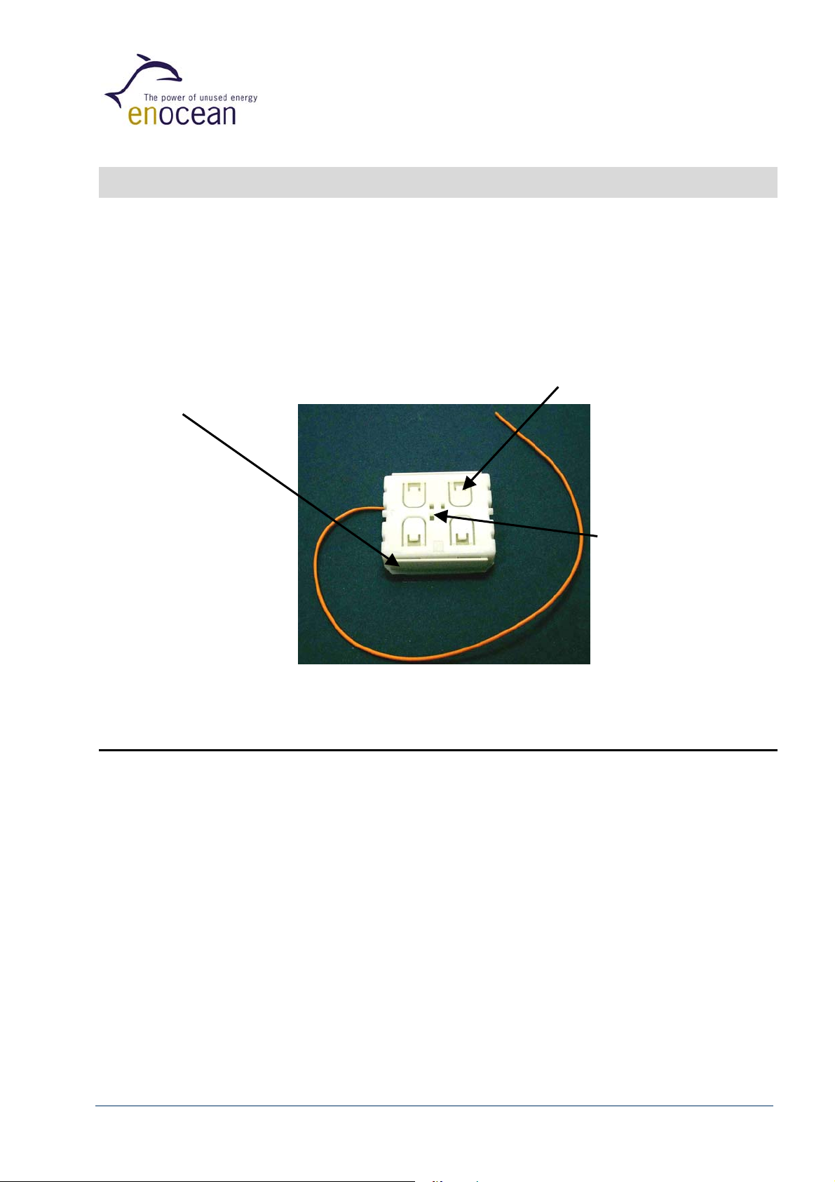
The radio transmitter device PTM 200C from EnOcean enables the implementation of
wireless remote controls without batteries. Power is provided by a built-in electrodynamic power generator.
The PTM 200C device serves the 315 MHz air interface protocol of EnOcean. Together with the
receiver device RCM 130C, this device can be easily integrated in operation and control units
for the implementation of different application specific system solutions.
(1) Energy bow
on both device sides
Figure 1: Electro-dynamic powered radio transmitter device PTM 200C
1.1 Functional Principle
(2) Contact nipples
for switch rocker
identification
Rotation axis for
pushbuttons or
switch rocker
A common electro-dynamic energy transducer is actuated by a bow (1), which can be pushed
from outside the device by an appropriate push button or switch rocker. When the energy bow
is pushed down, electrical energy is created and an RF telegram is transmitted including a 32bit device ID. Releasing the energy bow generates different telegram data, so every PTM
telegram contains the information that the bow was pressed or released.
“Long” or “Short” push button operation (the time between pushing and releasing the
pushbutton) can be easily detected by the receiver. By doing that, applications such as
dimming control or blinds control including slat action are simple to implement.
In addition, the PTM telegram transmits the operating status of the contact nipples (2) when
pressing the bow. This enables the identification of up to 2 appropriate switch rockers or up to
4 pushbuttons.
©EnOcean GmbH, W. Heller
Page 4 of 19
PTM 200C User Manual V1.01

1.2 Typical Applications
• Building installation
• Industrial automation
• Consumer electronics
Key applications are wall-mounted flat rocker switches with 1 or 2 rockers, as well as handheld
remote controls with up to 4 single pushbuttons. Because the RF transmitters are self-powered
(no batteries), maintenance-free RF systems are possible.
1.3 Features Overview
Power supply: ............................................................. Electro-dynamic Power Generator
(power generation by rocker operation)
Frequency / transmission power:....................... 315.0 MHz / typ. 3dBm at antenna input
Modulation type / data rate: ................................................................. ASK / 125 kbps
±0.1
Antenna:........................................................external whip antenna 26.8 cm,
ø1.3
mm
Transmission range: ..........................................up to 200 m free field, up to 30m indoor
Telegram packet length (sub-telegram):................................................ 0.7 ms +/-5%
No. of (redundant) packets:................................... 3 – 5 (depending on residual energy),
3 packets within about 20 ms, delay effected at random
Number of channels:................................................ 2 channels with 4 action states each
(upper/lower contact nipple is pressed/released)
Telegram type: ........................................................................................RPS of type 2
(allows interpretation of operating two buttons simultaneously)
Device identifier: ............................................ individual 32-bit ID (factory programmed)
1.4 Mechanical Interface
Device dimensions: ................................................................ 40.0 x 40.0 x 11.2*) mm
*) Height without label
Device weight: .............................................................................................20 g ± 1g
Energy bow travel / operating force: ...................................... 1.8 mm / approx. 7 N *)
*) at room temperature, only one energy bow may be actuated at the same time!
Restoring force at energy bow: .................................................................. 0.5N to 4N
For the correct function of the application, the specified minimal restoring force of 0.5N must be considered!
Number of operations: ...... typ 50.000 actuations tested according to VDE 0632 / EN 60669
Cover material: .................................................................................. Hostaform (POM)
Energy bow material: ............................................................................ PBT (50% GV)
©EnOcean GmbH, W. Heller
Page 5 of 19
PTM 200C User Manual V1.01
Energy Bow
Stopper
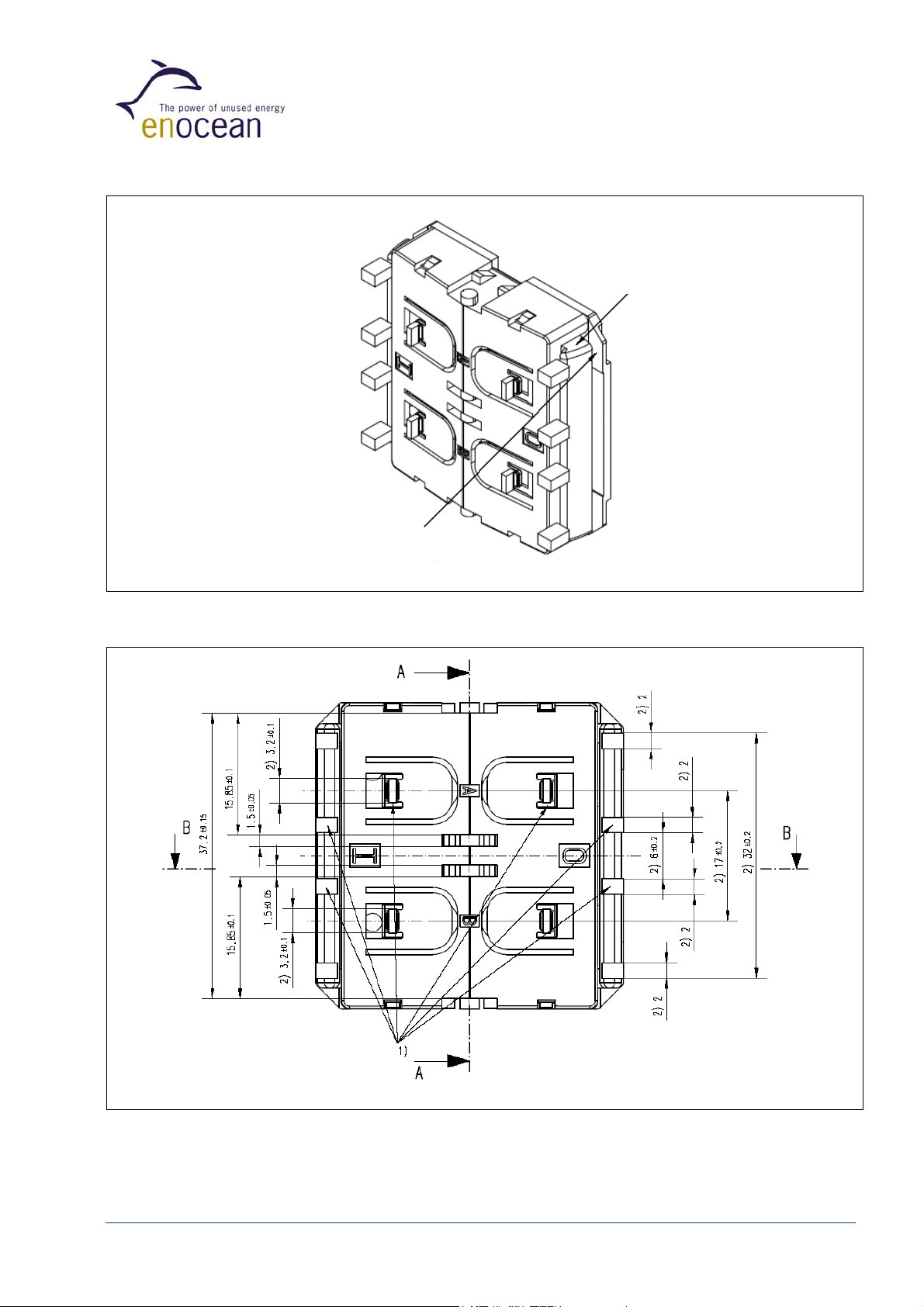
Figure 2: PTM 200C without antenna, tilted view (including rocker catwalks)
1) this catwalks are not needed when using one single rocker only 2) dimensions of rocker part
Figure 3: PTM 200C without antenna, top view (note cut A, B and C marking)
©EnOcean GmbH, W. Heller
Page 6 of 19
PTM 200C User Manual V1.01
 Loading...