

Page 1

USER MANUAL
EMDC – ENOCEAN MOTION DETECTOR AND LIGHT LEVEL SENSOR
© 2020 EnOcean | www.enocean.com EMDC User Manual | v1.1 | September 2020 | Page 1/77
Patent protected:
WO98/36395, DE 100 25 561, DE 101 50 128,
WO 2004/051591, DE 103 01 678 A1, DE 10309334,
WO 04/109236, WO 05/096482, WO 02/095707,
US 6,747,573, US 7,019,241
Observe precautions! Electrostatic sensitive devices!
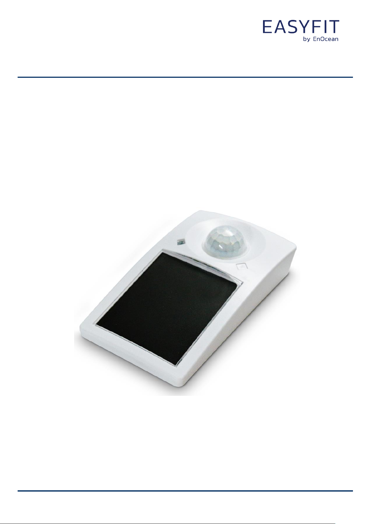
EMDC
EnOcean Motion Detector And Light Level Sensor
Page 2

USER MANUAL
EMDC – ENOCEAN MOTION DETECTOR AND LIGHT LEVEL SENSOR
© 2020 EnOcean | www.enocean.com EMDC User Manual | v1.1 | September 2020 | Page 2/77
REVISION HISTORY
The following major modifications and improvements have been made to this document:
Version
Author
Reviewer
Date
Major Changes
1.0
MKA
TM, MHe, LC
31 Mar 2020
Initial release
1.1
MKA
MKA
09 Sep 2020
Added ARIB certificate
Published by EnOcean GmbH, Kolpingring 18a, 82041 Oberhaching, Germany
www.enocean.com, info@enocean.com, phone +49 (89) 6734 6890
© EnOcean GmbH, All Rights Reserved
Important!
This information describes the type of component and shall not be considered as assured
characteristics. No responsibility is assumed for possible omissions or inaccuracies. Circuitry
and specifications are subject to change without notice. For the latest product specifications,
refer to the EnOcean website: http://www.enocean.com.
As far as patents or other rights of third parties are concerned, liability is only assumed for
modules, not for the described applications, processes and circuits.
EnOcean does not assume responsibility for use of modules described and limits its liability
to the replacement of modules determined to be defective due to workmanship. Devices or
systems containing RF components must meet the essential requirements of the local legal
authorities.
The modules must not be used in any relation with equipment that supports, directly or
indirectly, human health or life or with applications that can result in danger for people,
animals or real value.
Recycling information
Components of the modules are considered and should be disposed of as hazardous waste.
Please use suitable recycling operators for modules, components or packaging.
Page 3

USER MANUAL
EMDC – ENOCEAN MOTION DETECTOR AND LIGHT LEVEL SENSOR
© 2020 EnOcean | www.enocean.com EMDC User Manual | v1.1 | September 2020 | Page 3/77
TABLE OF CONTENT
1 General description ........................................................................................ 7
1.1 Basic functionality ......................................................................................... 7
1.2 Technical data ............................................................................................... 8
1.3 Environmental conditions ............................................................................... 9
1.4 Packaging information .................................................................................... 9
1.5 Ordering information ..................................................................................... 9
2 Functional description .................................................................................. 10
2.1 EMDC product overview ............................................................................... 10
2.2 Basic functionality ....................................................................................... 11
2.3 External product interface ............................................................................ 11
2.4 Internal product interface ............................................................................. 12
2.5 Functional modes ........................................................................................ 13
2.5.1 Standard operation mode ..................................................................... 13
2.5.2 Standby (Sleep) mode .......................................................................... 13
2.5.3 Walk test mode ................................................................................... 14
2.5.4 Learn mode......................................................................................... 14
2.5.5 Ambient light test mode ....................................................................... 14
2.5.6 Factory reset mode .............................................................................. 14
2.6 Reporting interval ........................................................................................ 15
2.6.1 Energy considerations .......................................................................... 15
2.6.2 Standard reporting interval ................................................................... 16
2.6.3 Occupancy-controlled reporting interval .................................................. 17
2.6.4 Illumination-controlled reporting interval ................................................ 18
2.6.5 Arbitration between reporting intervals ................................................... 18
3 Sensor functionality ..................................................................................... 19
3.1 Motion detection ......................................................................................... 19
3.1.1 PIR detection characteristics ................................................................. 19
3.2 Illumination measurement (light level sensor) ................................................. 20
3.3 Illumination measurement (solar cell) ............................................................ 20
3.4 Temperature ............................................................................................... 21
3.5 Energy level ............................................................................................... 21
3.6 Backup battery voltage ................................................................................ 21
4 User interface ............................................................................................. 22
4.1 LRN button and LED .................................................................................... 22
4.2 Factory Reset .............................................................................................. 23
4.3 Backup battery interface .............................................................................. 23
4.3.1 Safety remarks .................................................................................... 23
4.4 Sensitivity selection switch ........................................................................... 24
4.5 Device label ................................................................................................ 24
5 Radio communication ................................................................................... 25
5.1 Radio frame format ..................................................................................... 25
Page 4

USER MANUAL
EMDC – ENOCEAN MOTION DETECTOR AND LIGHT LEVEL SENSOR
© 2020 EnOcean | www.enocean.com EMDC User Manual | v1.1 | September 2020 | Page 4/77
5.1.1 ERP1 frame format .............................................................................. 25
5.1.2 ERP2 frame format .............................................................................. 25
5.2 EnOcean Equipment Profiles (EEP) and SIGNAL telegrams ................................ 26
5.2.1 EEP structure ...................................................................................... 26
5.2.2 4BS telegram structure ........................................................................ 27
5.2.3 Signal telegram structure ..................................................................... 27
5.2.4 Supported EEP types ............................................................................ 28
5.2.5 Supported SIGNAL types ...................................................................... 29
6 Security ..................................................................................................... 30
6.1 Basic concepts ............................................................................................ 30
6.2 Telegram encryption .................................................................................... 30
6.2.1 Telegram authentication ....................................................................... 31
6.2.2 Dynamic security key modification ......................................................... 32
6.3 Security parameters .................................................................................... 33
6.3.1 EURID ................................................................................................ 33
6.3.2 Security key ........................................................................................ 33
6.3.3 Rolling code ........................................................................................ 33
6.3.4 Security algorithm ............................................................................... 33
6.4 Secure teach-in telegram ............................................................................. 34
6.4.1 Security level format (SLF) ................................................................... 35
6.5 EMDC security implementation ...................................................................... 35
7 EMDC commissioning ................................................................................... 36
7.1 Radio-based commissioning .......................................................................... 37
7.2 QR code commissioning ............................................................................... 37
7.2.1 Commissioning QR code structure .......................................................... 37
7.2.2 Commissioning QR code format ............................................................. 38
7.3 Commissioning via NFC interface ................................................................... 38
8 NFC interface .............................................................................................. 39
8.1 NFC interface parameters ............................................................................. 39
8.2 NFC access protection .................................................................................. 39
8.3 Using the NFC interface ................................................................................ 40
8.3.1 PC with dedicated NFC reader ............................................................... 40
8.3.2 Smartphones with NFC ......................................................................... 40
8.4 NFC interface functions ................................................................................ 41
8.4.1 NFC interface state machine .................................................................. 41
8.4.2 IDLE state ........................................................................................... 42
8.4.3 READY 1 state ..................................................................................... 42
8.4.4 READY 2 state ..................................................................................... 42
8.4.5 ACTIVE state ....................................................................................... 42
8.4.6 Read command ................................................................................... 43
8.4.7 Write command ................................................................................... 43
8.4.8 Password authentication (PWD_AUTH) command ..................................... 44
9 NFC registers .............................................................................................. 45
9.1 NFC memory areas ...................................................................................... 45
9.2 PRODUCT NDEF........................................................................................... 46
Page 5

USER MANUAL
EMDC – ENOCEAN MOTION DETECTOR AND LIGHT LEVEL SENSOR
© 2020 EnOcean | www.enocean.com EMDC User Manual | v1.1 | September 2020 | Page 5/77
9.3 USER NDEF................................................................................................. 46
9.4 NFC HEADER............................................................................................... 47
9.4.1 NFC HEADER area structure .................................................................. 47
9.5 CONFIGURATION ......................................................................................... 48
9.5.1 Using the NFC configuration functionality ................................................ 48
9.5.2 CONFIGURATION area structure ............................................................ 48
9.5.3 NFC_PIN_CODE ................................................................................... 49
9.5.4 PRODUCT_ID ...................................................................................... 49
9.5.5 USER_KEY .......................................................................................... 50
9.5.6 SECURITY_KEY_MODE .......................................................................... 50
9.5.7 SECURITY_MODE ................................................................................. 51
9.5.8 EEP .................................................................................................... 52
9.5.9 SIGNAL .............................................................................................. 53
9.5.10 LED_MODE ......................................................................................... 54
9.5.11 FUNCTIONAL_MODE ............................................................................. 55
9.5.12 STANDARD_TX_INTERVAL .................................................................... 56
9.5.13 OCCUPIED_TX_INTERVAL ..................................................................... 57
9.5.14 THRESHOLD_CFG ................................................................................ 58
9.5.15 LIGHT_SENSOR_CFG ........................................................................... 59
9.5.16 TEMP_SENSOR_CFG ............................................................................. 60
9.5.17 SOLAR_THRESHOLD............................................................................. 61
9.5.18 SOLAR_TX_INTERVAL .......................................................................... 62
9.5.19 LIGHT_THRESHOLD ............................................................................. 63
9.5.20 LIGHT_TX_INTERVAL ........................................................................... 64
9.5.21 AMBIENT_LIGHT_TEST_RESULT ............................................................ 65
9.6 USER DATA ................................................................................................ 65
10 Installation recommendations ....................................................................... 66
10.1 Setup instructions ....................................................................................... 66
10.2 Motion detection ......................................................................................... 67
10.3 Light level measurement .............................................................................. 68
10.3.1 Ambient light sensor ............................................................................ 68
10.3.2 Solar cell ............................................................................................ 69
10.4 Energy harvesting ....................................................................................... 69
10.5 NFC configuration ........................................................................................ 70
11 Regulatory notes ......................................................................................... 71
11.1 European Union........................................................................................... 71
11.1.1 Declaration of conformity ...................................................................... 71
11.1.2 Waste treatment .................................................................................. 71
11.2 FCC (United States) ..................................................................................... 72
11.2.1 FCC Grant Of Equipment Authorization ................................................... 72
11.2.2 FCC (United States) Regulatory Statement .............................................. 73
11.3 ISED (former Industry Canada) Certification ................................................... 74
11.3.1 ISED Technical Acceptance Certificate .................................................... 74
11.3.2 ISED Usage Conditions ......................................................................... 75
11.4 ARIB (Japan) .............................................................................................. 76
11.4.1 ARIB construction type conformity certificate .......................................... 76
Page 6

USER MANUAL
EMDC – ENOCEAN MOTION DETECTOR AND LIGHT LEVEL SENSOR
© 2020 EnOcean | www.enocean.com EMDC User Manual | v1.1 | September 2020 | Page 6/77
12 Product history ............................................................................................ 77
Page 7

USER MANUAL
EMDC – ENOCEAN MOTION DETECTOR AND LIGHT LEVEL SENSOR
© 2020 EnOcean | www.enocean.com EMDC User Manual | v1.1 | September 2020 | Page 7/77
1 General description
This user manual describes the functionality of the family of ceiling-mounted motion detectors and light level sensors EMDC.
The EMDC product family consists of the following members:
◼ EMDCA using 868.300 MHz radio (main market Europe)
◼ EMDCU using 902.875 MHz radio (main market US / Canada)
◼ EMDCJ using 928.350 MHz radio (main market Japan)
The term “EMDC” is used throughout this user manual to describe all three variants unless
otherwise noted.
1.1 Basic functionality
EMDC enables the realization of energy harvesting wireless occupancy and light level sensors
for light, building or industrial control systems communicating with the 868.3 MHz (EMDCA),
902.875 MHz (EMDCU) or 928.35 MHz (EMDCJ) versions of the EnOcean radio standard.
EMDC uses a passive infrared (PIR) sensor to detect motion and a dedicated illumination
sensor to measure the amount of ambient light.
EMDC reports periodically (approximately every 2 minutes when no motion is detected, approximately every 1 minute when motion is detected) the latest motion detection status
(motion detected, or no motion detected). EMDC will report immediately if motion is detected
for the first time after a period without detected motion (e.g. when a person is entering a
room).
EMDC will use EnOcean Equipment Profiles (EEP) of the EnOcean radio standard for the reporting of the motion detection status. Depending on the selected EEP, EMDC can additionally
report the measured ambient light level and the measured temperature status.
EMDC is self-supplied via an integrated solar cell which generates the energy required for its
operation. EMDC requires 50 lux illumination for 6 hours per day directly at the solar cell
which typically is equivalent 200 lux for 6 hours per day to at room level. EMDC is fully selfpowered (no batteries required) under these lighting conditions.
For cases where sufficient ambient light is not available, EMDC provides the option to mount
a CR2032 backup battery.
EMDC supports both standard and high security mode as specified by EnOcean Alliance. In
high security mode, radio telegrams transmitted by EMDC are both encrypted and authenticated using AES-128 with a device-unique private key and a sequence counter. This ensures
confidentiality, integrity and authenticity of the transmitted telegrams and prevents telegram
replay (retransmission of previously transmitted telegrams).
Page 8

USER MANUAL
EMDC – ENOCEAN MOTION DETECTOR AND LIGHT LEVEL SENSOR
© 2020 EnOcean | www.enocean.com EMDC User Manual | v1.1 | September 2020 | Page 8/77
1.2 Technical data
Transmission Frequency / Power
EMDCA: 868.300 MHz / +5 dBm
EMDCU: 902.875 MHz / + 99dBuV
EMDCJ: 928.350 MHz / 0 dBm
Transmission Data Rate
125 kbit / s
Communication Range (for guidance only)
200 m free range
30 m for indoor environment
Recommended Installation
Ceiling-mounted at 2.5 m (8.5 ft) … 3 m (10 ft) height
Motion Detection Radius
typ. 5 m (16 ft.) when mounted 2.5 m (8.5 ft.) high
Light Level Sensor Range / Accuracy
0 … 65000 Lux / +- 10 %
Update Rate With / Without Detected Motion
Approximately every 2 minutes / every 1 minute
Configurable via NFC
Initial motion detection is reported immediately
Supported EEP (Selectable Via NFC)
A5-07-03 (default)
A5-07-01
A5-08-01, A5-08-02, A5-08-03
User interface
LRN button
Sensitivity selection switch
Notification LED
Configuration interface
NFC (ISO 14443)
Power supply
Integrated solar cell
Required illumination to sustain operation
200 lux for 6 hours per day
Charge time from empty to first transmission
5 minutes at 400 Lux
Operating time in darkness
96 hours (after full charge)
Backup power supply (optional)
CR2032
Backup battery life
Infrequent bright light (200 lux for 2 hrs every day)
Consistent low light (65 lux for 5 hrs every day)
Total Darkness
Up to 15 years
Up to 12.5 years
Up to 5 years
Dimensions
113,2 mm L x 65,5 mm W x 30,7 mm H
(4.46” L x 2.58” W x 1.21” H)
Page 9

USER MANUAL
EMDC – ENOCEAN MOTION DETECTOR AND LIGHT LEVEL SENSOR
© 2020 EnOcean | www.enocean.com EMDC User Manual | v1.1 | September 2020 | Page 9/77
1.3 Environmental conditions
Maximum Operating Temperature
(1)
0 … 60°C / 32 … 140 F (indoor use only)
Recommended Operating Temperature
(1)
0 … 30°C / 32 … 85 F (indoor use only)
Humidity
20% to 85% r.h. (non-condensing)
Note 1: PIR detection requires that the moving object to be detected is significantly warmer
than its environment. For the case of human motion, this means that the environment needs
to be significantly colder than the human body temperature of 36.5 °C / 98 F.
1.4 Packaging information
Packaging Unit 12 units
Packaging Method Box / pallet
1.5 Ordering information
Type
Ordering Code
Frequency
EMDCA
E6201-K515
863.300 MHz
EMDCU
E6251-K515
902.875 MHz
EMDCJ
E6261-K515
928.350 MHz
Page 10
USER MANUAL
EMDC – ENOCEAN MOTION DETECTOR AND LIGHT LEVEL SENSOR
© 2020 EnOcean | www.enocean.com EMDC User Manual | v1.1 | September 2020 | Page 10/77
2 Functional description
2.1 EMDC product overview
The energy harvesting ceiling-mounted motion and illumination sensor EMDC from EnOcean
provides wireless motion and illumination sensing functionality without batteries. Power is
provided by a built-in solar cell harvesting available light from the environment.
EMDC transmits sensor data based on the EnOcean radio standard using EnOcean Equipment
Profiles (EEP).
The outer appearance of EMDC is shown in Figure 1 below.
Figure 1 – EMDC external view
Page 11

USER MANUAL
EMDC – ENOCEAN MOTION DETECTOR AND LIGHT LEVEL SENSOR
© 2020 EnOcean | www.enocean.com EMDC User Manual | v1.1 | September 2020 | Page 11/77
2.2 Basic functionality
EMDC devices contain a passive infrared sensor that detects changes in the received infrared
radiation which are characteristic for the movement of persons. In addition, EMDC measures
the ambient light level via a dedicated sensor and the temperature using its integrated microcontroller.
EMDC integrates a solar cell that generates the required energy for its operation from available ambient light.
The user interface of EMDC consists of one button for simple configuration tasks and one LED
to provide user feedback. Configuration of EMDC parameters is possible via an integrated
NFC (ISO 14443) interface.
EMDC is designed for ceiling mounting. It can be mounted on most ceilings with suitable
screws or mounted on dropped ceilings using wire brackets.
2.3 External product interface
The external product interface consists of the following items:
◼ Infrared lens in conjunction with a passive infrared sensor for motion detection
◼ Ambient light sensor for light measurement
◼ Solar cell can for powering the device in normal lighting conditions
◼ User interface. With one button (LRN) and one LED simple configuration and test
◼ Internal NFC antenna (not visible) providing access to the NFC configuration
◼ Wall mount plate (with opening slot for removal) for product mounting
Figure 2 below shows the location of these items.
Figure 2 – EMDC front and rear view
Page 12
USER MANUAL
EMDC – ENOCEAN MOTION DETECTOR AND LIGHT LEVEL SENSOR
© 2020 EnOcean | www.enocean.com EMDC User Manual | v1.1 | September 2020 | Page 12/77
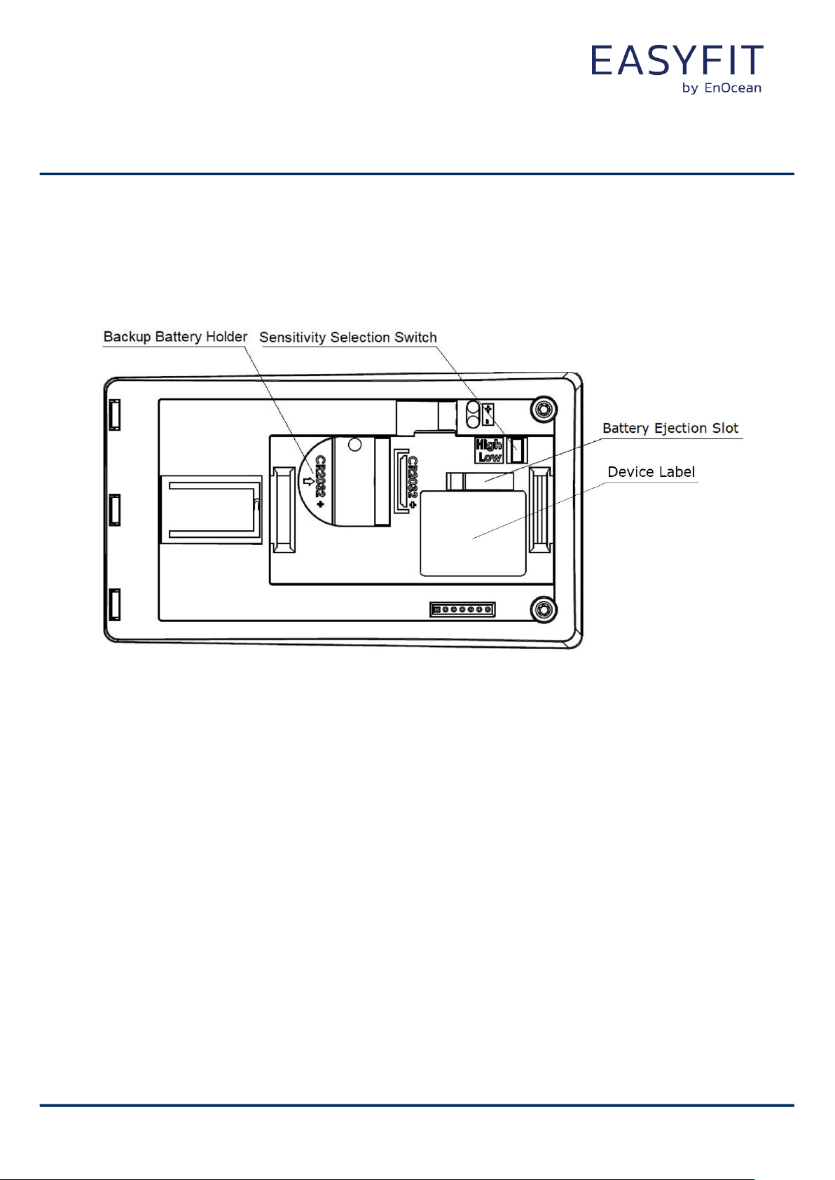
2.4 Internal product interface
EMDC contains a holder for a CR2032 battery and a PIR sensitivity selection switch as shown
in Figure 3 below.
Figure 3 – EMDC internal view
The internal product interface is accessible after removing the wall mount plate.
If EMDC has not yet been mounted onto the ceiling, then the wall mount plate can be removed
by inserting a screwdriver (or similar tool) into the opening slot shown in Figure 2 and pushing
the wall mount plate outwards.
If the EMDC wall mount plate is already attached to the ceiling, then EMDC can be removed
by gently pulling the housing.
A backup battery can be inserted into the backup battery holder and removed by inserting a
suitable tool into the battery ejection slot as described in chapter 4.3.
Page 13

USER MANUAL
EMDC – ENOCEAN MOTION DETECTOR AND LIGHT LEVEL SENSOR
© 2020 EnOcean | www.enocean.com EMDC User Manual | v1.1 | September 2020 | Page 13/77
2.5 Functional modes
EMDC supports six types of functional modes:
◼ Standard operation mode
◼ Standby (sleep) mode
◼ Learn mode
◼ Walk test mode
◼ Ambient light test mode
◼ Factory reset mode
These modes are described below.
2.5.1 Standard operation mode
During standard operation, EMDC wakes up periodically and reports the motion detection
status and – depending on the selected EEP also the current light level and the temperature
status - using data telegrams.
The motion detection functionality is described in chapter 3.1 and the light level sensing
functionality in chapter 3.2 and chapter 3.3 respectively.
The EMDC wake-up timer is configured to wake-up EMDC approximately every 2 minutes
during periods without detected motion and approximately every 1 minute during periods
with detected motion. If motion is detected for the first time after a period without motion,
then EMDC wakes up immediately.
Both the occupied and the unoccupied wake-up intervals are affected at random in order to
increase the robustness of the radio transmission and to comply with regulatory requirements.
It is possible to change the wake-up intervals using the NFC interface. In case of reducing
the reporting interval, the resulting increase in required energy (provided by the available
light or a backup battery) has to be considered.
2.5.2 Standby (Sleep) mode
Standby (Sleep) mode is used to conserve as much energy as possible during periods of
storage or transport. All functionality – except those needed to return to standard operation
mode – is disabled in this mode.
Standby mode can be selected using the LRN button as described in chapter 4.1 or using the
NFC interface as described in chapter 9.5.11.
Page 14

USER MANUAL
EMDC – ENOCEAN MOTION DETECTOR AND LIGHT LEVEL SENSOR
© 2020 EnOcean | www.enocean.com EMDC User Manual | v1.1 | September 2020 | Page 14/77
2.5.3 Walk test mode
Walk test mode is used to verify the motion detection coverage of the device via visual feedback from the LED which will blink whenever motion is detected.
Walk test mode can be selected using the LRN button as described in chapter 4.1 or using
the MODE field of the FUNCTIONAL_MODE NFC register as described in chapter 9.5.11.
Walk test mode will be active for a period of 120 seconds; it will end immediately if the LRN
button is pressed while walk test mode is active.
2.5.4 Learn mode
In learn mode, EMDC will transmit a Teach-in telegram to communicate the device source
address, the security key and the EnOcean Equipment Profile (EEP) used by EMDC to a receiver. After that transmission, EMDC will return back to standard operation mode.
Learn mode can be selected using the LRN button as described in chapter 4.1 or using the
MODE field of the FUNCTIONAL_MODE NFC register as described in chapter 9.5.11.
2.5.5 Ambient light test mode
During installation, EMDC can measure and report the amount of ambient light available at
its solar cell in order to determine a suitable installation location as discussed in chapter 10.4.
Upon activation of ambient light test mode, EMDC will first wait for 15 seconds so that the
installer can leave the area to ensure a relevant measurement result.
After that, EMDC will take measurements of the ambient light level using its solar cell every
5 seconds for a period of one minute and compute the average illumination based on those
measurements. The computed average illumination is then available in the NFC register ILLUMINATION_TEST_RESULT as described in chapter 9.5.21.
Illumination test mode can be selected using the MODE field of the FUNCTIONAL_MODE NFC
register as described in chapter 9.5.11.
2.5.6 Factory reset mode
EMDC can be reset to its standard settings using factory reset mode. Upon entering this
mode, EMDC will reset all configuration registers to their default settings and then restart
operation in standard operation mode.
Factory reset mode can be selected using the LRN button as described in chapter 4.1 or using
the MODE field of the FUNCTIONAL_MODE NFC register as described in chapter 9.5.11.
Page 15

USER MANUAL
EMDC – ENOCEAN MOTION DETECTOR AND LIGHT LEVEL SENSOR
© 2020 EnOcean | www.enocean.com EMDC User Manual | v1.1 | September 2020 | Page 15/77
2.6 Reporting interval
EMDC will always report the initial motion detection after a period without detected motion
immediately. The rate of subsequent updates (reporting interval = time between two data
telegrams) can be configured by the user based on different conditions.
The minimum configurable reporting interval is 3 seconds and the maximum possible transmission interval is 65535 seconds.
2.6.1 Energy considerations
The default reporting interval of 120 seconds (one update every two minutes) when unoccupied (no motion detected) and 60 seconds (one update every minute) when occupied (motion
detected) is adjustable using the NFC interface as discussed in the subsequent chapters.
Lowering the reporting interval will increase its power consumption since EMDC will measure
and transmit more often. Likewise, increasing the reporting interval will reduce power consumption since it will measure and transmit less often.
To select the right reporting interval, it is essential to determine the amount of harvestable
energy. EMDC harvests energy from the available ambient light; therefore, the amount of
available energy is determined mainly by the intensity of the available light and the amount
of time during which the light is available.
The amount of available ambient light can be determined by executing an ambient light test
as described in chapter 2.5.5. The light availability period (the time during which the ambient
light is available) has to be determined based on the lighting scheme used for the environment where EMDC is installed.
EMDC is designed to provide one update per minute while a room is occupied based on 200
lux of ambient light available for 6 hours per day.
The minimum supported update interval (for the case of a room being occupied) for selfsupplied operation based on other conditions is summarized in Table 1 below. This table
assumes that the update interval for the case of an unoccupied room will be double this
value.
6 hrs / day
8 hrs / day
10 hrs / day
12 hrs / day
50 lux
Not supported
Not supported
180 s
120 s
100 lux
120 s
90 s
90 s
60 s
150 lux
90 s
60 s
60 s
45 s
200 lux
60 s
45 s
45 s
30 s
300 lux
45 s
30 s
30 s
20 s
400 lux
30 s
25 s
25 s
15 s
500 lux
25 s
20 s
20 s
15 s
Table 1 – Minimum self-supplied reporting intervals
Page 16
USER MANUAL
EMDC – ENOCEAN MOTION DETECTOR AND LIGHT LEVEL SENSOR
© 2020 EnOcean | www.enocean.com EMDC User Manual | v1.1 | September 2020 | Page 16/77
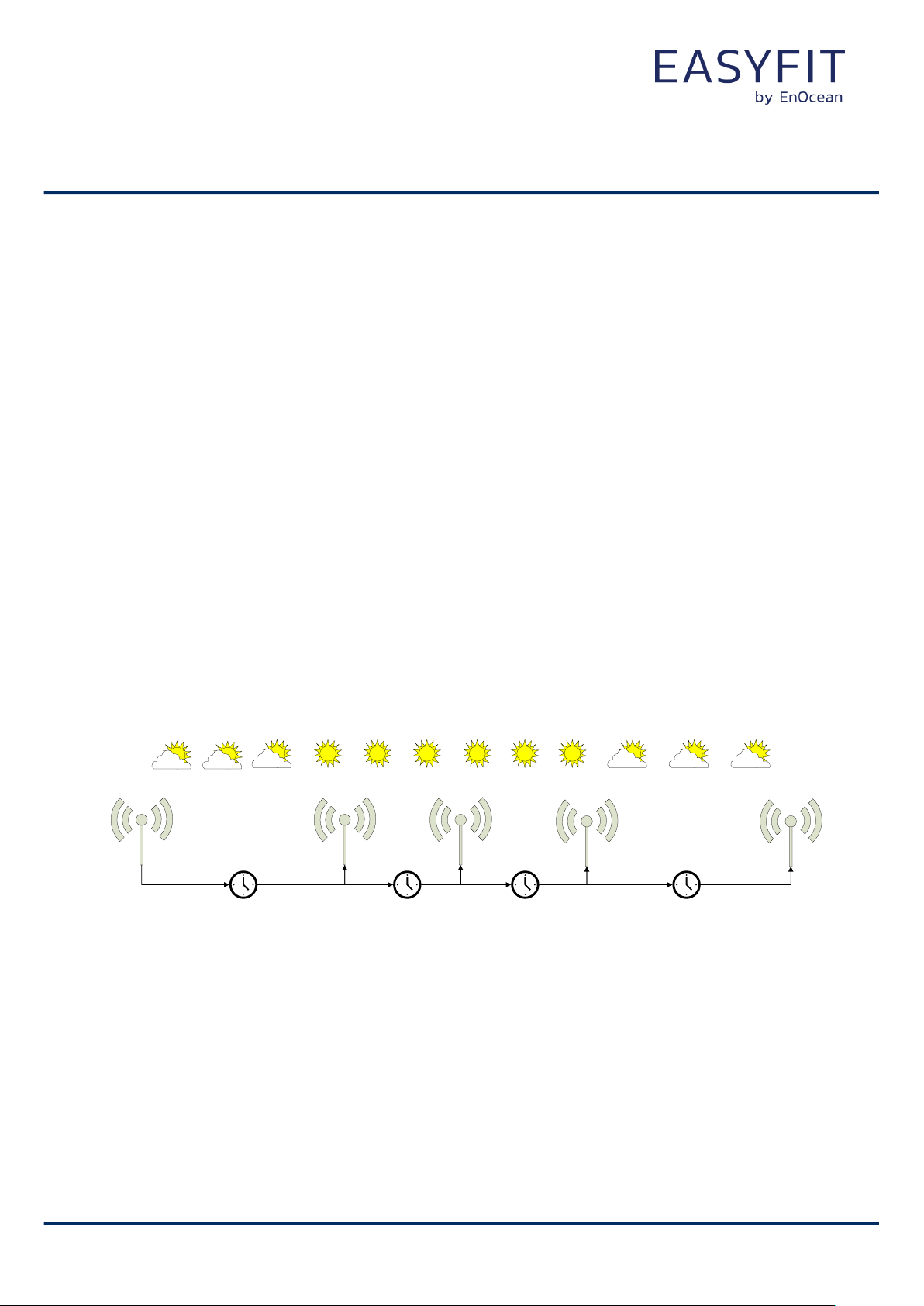
2.6.2 Standard reporting interval
The standard reporting interval determines the longest interval between two status updates
of EMDC, i.e. the minimum update rate.
EMDC can be configured to use a lower reporting interval, i.e. a higher update rate, based
on occupancy and available light as described below. But under no circumstances will EMDC
report with a longer reporting interval, i.e. a lower update rate, than the standard reporting
interval.
The default setting for the standard reporting interval is one status update once every 120
seconds (2 minutes). This means that under all conditions, EMDC will at least report its status
once every 120 seconds.
The standard reporting interval can be adjusted using the STANDARD_TX_INTERVAL NFC
register as described in chapter 9.5.12.
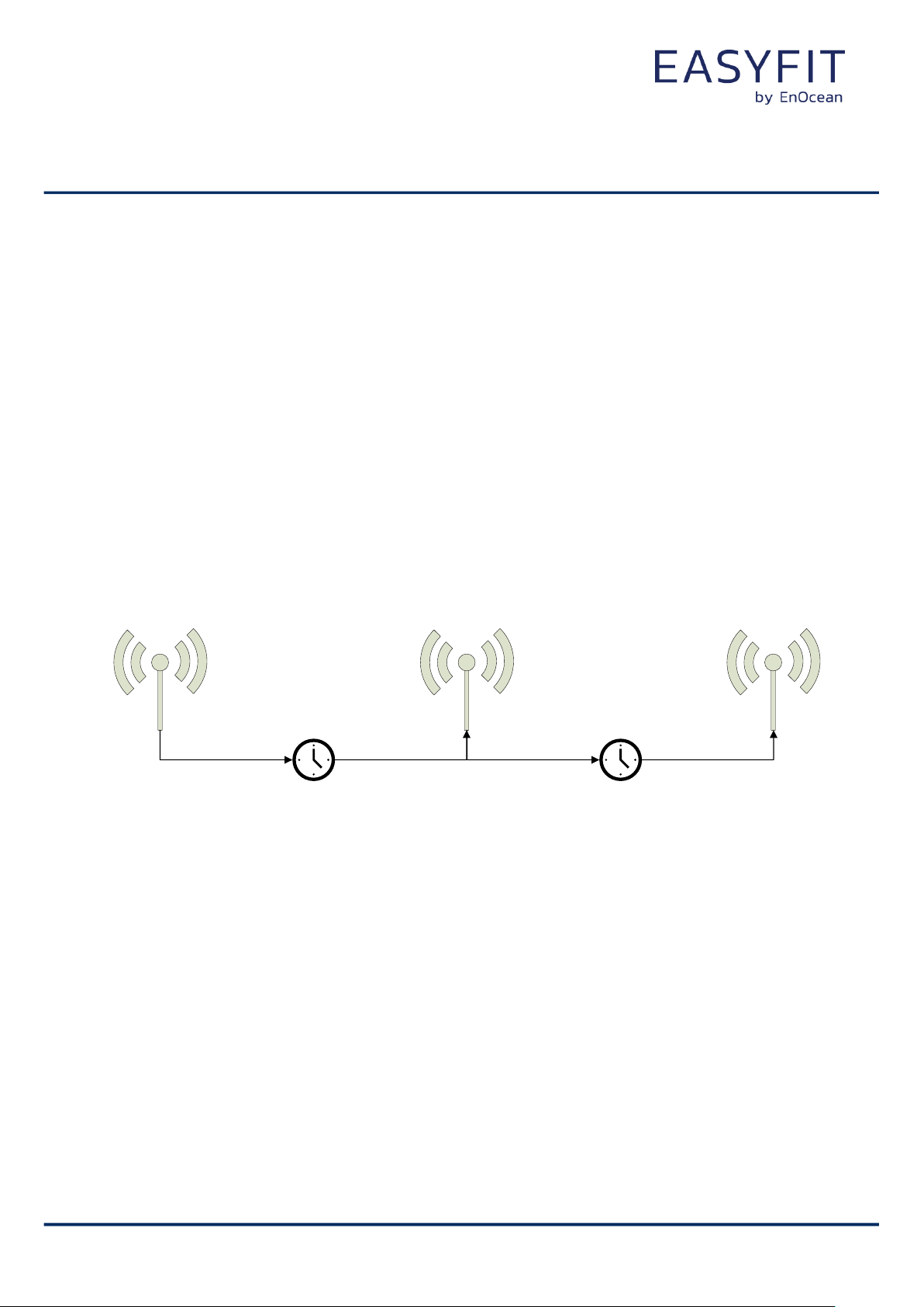
Figure 4 below illustrates the use of the standard reporting interval.
STANDARD_TX_INTERVAL STANDARD_TX_INTERVAL
Figure 4 – Standard reporting interval
Page 17
USER MANUAL
EMDC – ENOCEAN MOTION DETECTOR AND LIGHT LEVEL SENSOR
© 2020 EnOcean | www.enocean.com EMDC User Manual | v1.1 | September 2020 | Page 17/77
2.6.3 Occupancy-controlled reporting interval
If a room is occupied, then it might be desirable to receive status updates more often to
determine the current light level. EMDC can therefore be configured to use a lower reporting
interval, i.e. a higher update rate, while motion is detected.
The default setting of the occupied reporting interval is 60 seconds. This setting can be
changed using the OCCUPIED_TX_INTERVAL NFC register as described in chapter 9.5.13.
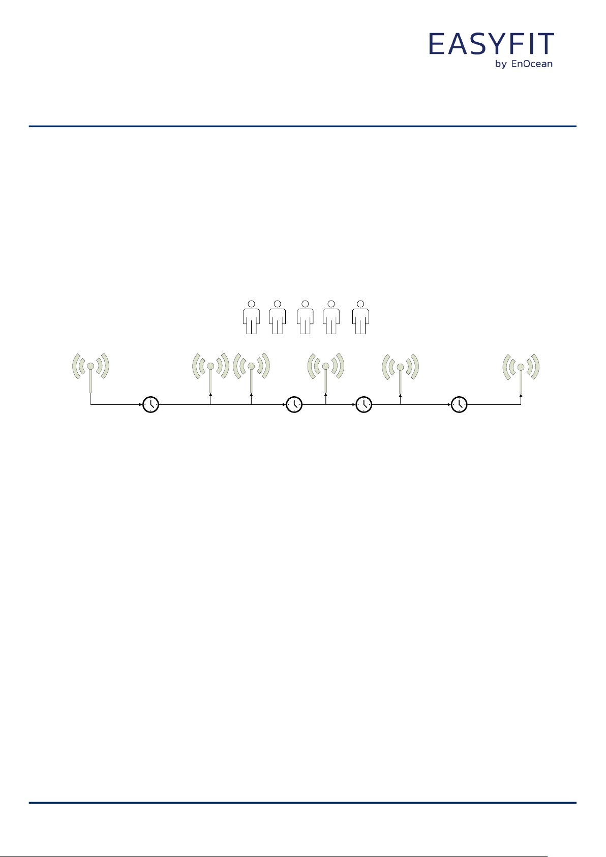
Figure 5 below illustrates the use of the occupancy-controlled reporting interval.
STANDARD_ TX_INTERVAL OCCUPIED_T X_INTERVAL
OCCUPIED_T X_INTERVAL STANDARD_ TX_INTERVAL
Immediately
Figure 5 – Occupancy-controlled reporting interval
Page 18
USER MANUAL
EMDC – ENOCEAN MOTION DETECTOR AND LIGHT LEVEL SENSOR
© 2020 EnOcean | www.enocean.com EMDC User Manual | v1.1 | September 2020 | Page 18/77
2.6.4 Illumination-controlled reporting interval
If sufficient ambient light is available, then it might be desirable to receive status updates
more often. For this, there are typically two main use cases:
◼ Adjust the update rate based on the ambient light available for harvesting
◼ Report more often during daytime (or when an office is lit) and less often during
night-time (or when an office is dark) to adapt the reporting to the usage pattern
In both cases, the lower update rate (defined by the standard reporting interval) would be
used whenever the ambient light level is below a certain threshold. The higher update rate
(defined by the light level-controlled reporting interval) would be used whenever the ambient
light level is above a certain threshold.
In EMDC, the light threshold and the reporting interval rate to be used when the measured
light level is above the threshold can be configured using the NFC interface as defined in
chapter 9.5.
It is possible to define different thresholds and reporting intervals for the solar cell (harvested
energy) and the light level sensor (measured light level).
Figure 6 below illustrated the use of the illumination-controlled reporting interval.
STANDARD_TX_INTERVAL SOLAR_CELL_TX_INTERVAL STANDARD_TX_INTERVALSOLAR_CELL_TX_INTERVAL
LIGHT_SENSOR_TX_INTERVAL LIGHT_SENSOR_TX_INTERVAL
Figure 6 – Illumination-controlled reporting interval
2.6.5 Arbitration between reporting intervals
If more than one condition for a lower reporting interval applies – e.g. if a room is both occupied and brightly lit – then the lowest of the corresponding reporting intervals will be selected.
Page 19
USER MANUAL
EMDC – ENOCEAN MOTION DETECTOR AND LIGHT LEVEL SENSOR
© 2020 EnOcean | www.enocean.com EMDC User Manual | v1.1 | September 2020 | Page 19/77
3 Sensor functionality
EMDC implements the following sensor functions:
◼ Motion detection using the passive infrared sensor (PIR)
◼ Illumination measurement using the light level sensor
◼ Illumination measurement using the solar cell
◼ Energy level of the energy store
◼ Supply voltage of the backup battery (if present)
These functions are described in detail in the subsequent chapters.
3.1 Motion detection
EMDC contains an integrated passive infrared (PIR) sensor that can detect moving objects
based on the temperature difference between the moving object and its environment.
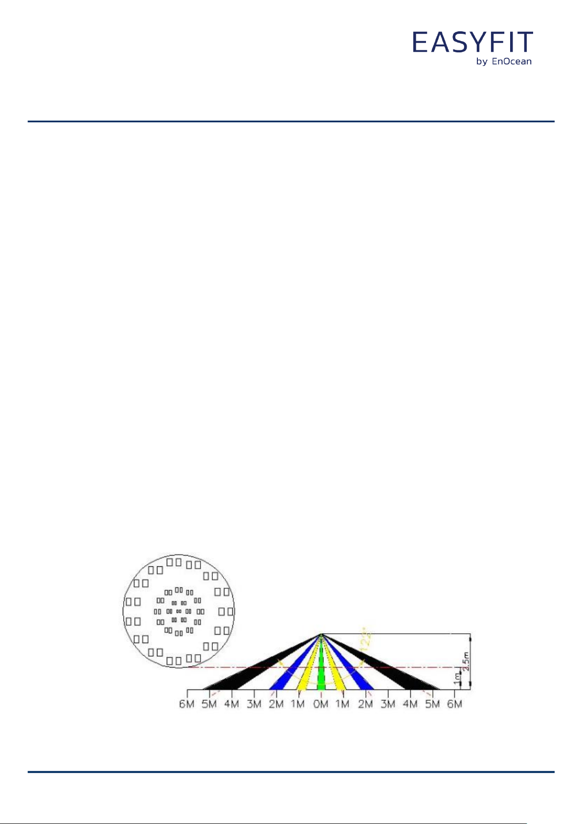
3.1.1 PIR detection characteristics
EMDC is designed to detect movement within a radius of up to 5 m (16 ft.) when mounted
at a ceiling of 3 m (10 ft.) height. The recommended coverage area for best detection performance is within a radius of 3 m (10 ft).
Figure 7 shows the PIR detection pattern.
Figure 7 – EMDC PIR detection pattern
Page 20
USER MANUAL
EMDC – ENOCEAN MOTION DETECTOR AND LIGHT LEVEL SENSOR
© 2020 EnOcean | www.enocean.com EMDC User Manual | v1.1 | September 2020 | Page 20/77
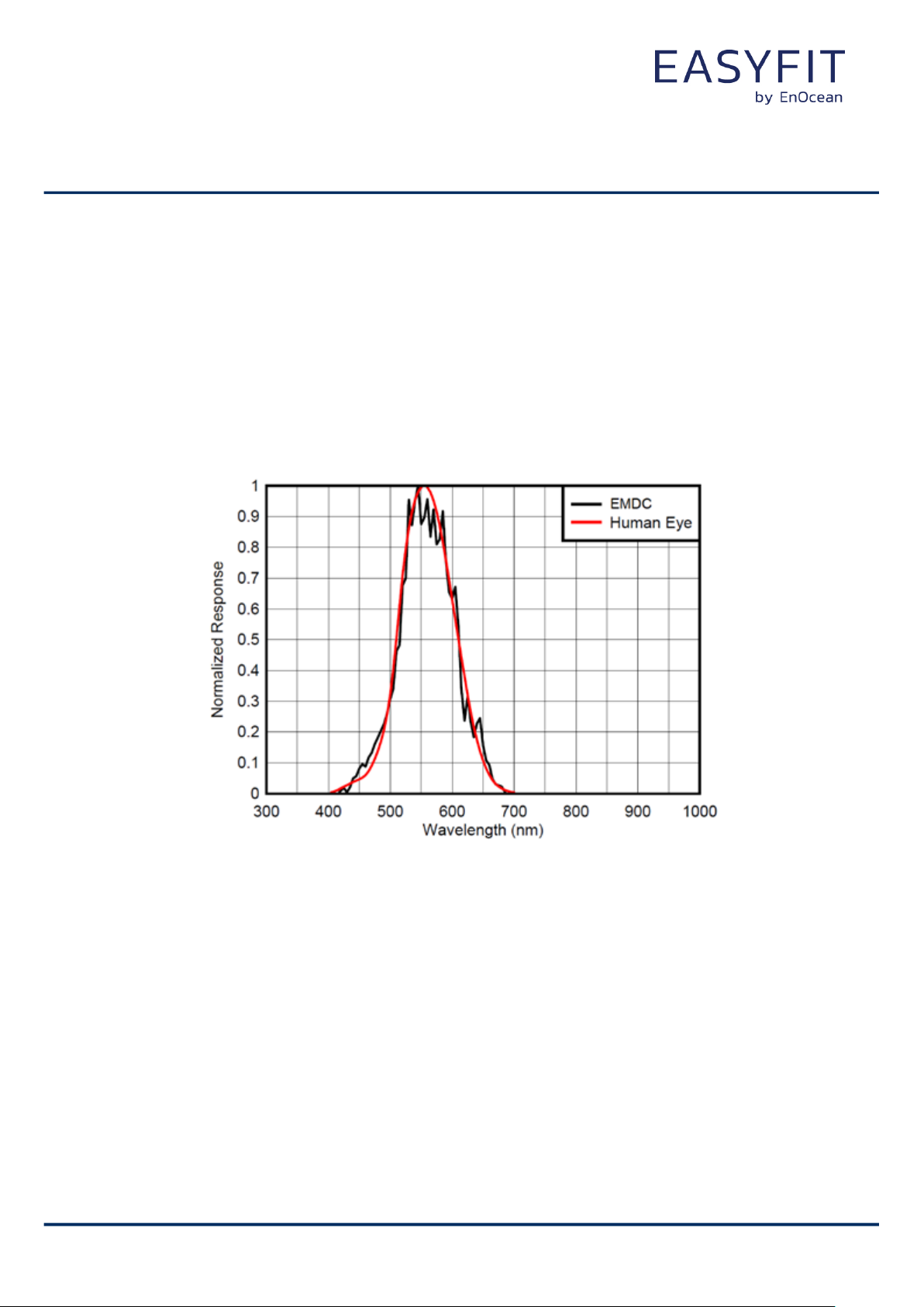
3.2 Illumination measurement (light level sensor)
EMDC integrates a dedicated illumination sensor used to accurately measure and report the
light level directly underneath (e.g. on the desk surface).
This sensor has a narrow aperture and a spectral response optimized to mimic the human
eye’s perception of ambient light. It reports the light level directly underneath the sensor
(spot measurement).
Figure 8 shows the spectrum response of the EMDC illumination sensor compared to that of
the human eye.
Figure 8 – Spectrum response of the illumination sensor
3.3 Illumination measurement (solar cell)
EMDC can use SIGNAL telegrams - as described in chapter 5.2 - to report the light level by
measuring the energy generated by the solar cell. This functionality can be used both to
ensure that sufficient ambient light is available to power the device and to measure incoming
light if the solar cell is oriented towards the window.
Reporting of the solar cell light level can be enabled and disabled via SIGNAL register of the
NFC interface as described in chapter 9.5.9. By default, the reporting is disabled.
In addition, the light level of the solar cell can be reported instead of the light level of the
ambient light level sensor. The selection is done using the LIGHT_SENSOR_CFG register of
the NFC interface as described in chapter 9.5.15.
Page 21

USER MANUAL
EMDC – ENOCEAN MOTION DETECTOR AND LIGHT LEVEL SENSOR
© 2020 EnOcean | www.enocean.com EMDC User Manual | v1.1 | September 2020 | Page 21/77
3.4 Temperature
EMDC uses the temperature monitor within the microcontroller to detect abnormal temperature conditions (very hot, very cold, quick change of temperature). This temperature monitor
provides a resolution of 1°C, i.e. it reports only integer values. EMDC provide the option for
offset calibration of the temperature monitor as described in chapter 9.5.16.
Due to the limited accuracy of the temperature monitor, the temperature reporting of EMDC
is not suitable for high accuracy HVAC control.
3.5 Energy level
EMDC can measure the voltage of the internal energy store which stores the harvested energy to supply the device when the ambient light is insufficient to power the device.
Based on the measured voltage, EMDC will estimate the energy level (amount of remaining
energy) and report this as a percentage between 0% (empty) and 100% (fully charged).
The calculated energy level can be reported using SIGNAL telegrams as described in chapter
5.2. The measurement and reporting can be enabled and disabled via the SIGNAL register of
the NFC interface as described in chapter 9.5.9. By default, the reporting of the remaining
energy is enabled and will be executed once for every 32 data telegrams.
Note that the reported energy level can only provide rough guidance as the actual energy
level depends on several factors (most notably the ambient temperature).
3.6 Backup battery voltage
EMDC can measure the supply voltage level of external backup battery used to supply the
device when the available ambient light is insufficient for energy harvesting operation.
The measured backup battery voltage can be reported using SIGNAL telegrams as described
in chapter 5.2. The measurement and reporting can enabled and disabled via the SIGNAL
register of the NFC interface as described in chapter 9.5.9. By default, the reporting is disabled.
Page 22

USER MANUAL
EMDC – ENOCEAN MOTION DETECTOR AND LIGHT LEVEL SENSOR
© 2020 EnOcean | www.enocean.com EMDC User Manual | v1.1 | September 2020 | Page 22/77
4 User interface
The user interface of EMDC consists of the following items:
◼ LRN button and LED
◼ Backup battery interface
◼ Sensitivity selection switch
◼ Device label
Please refer to chapter 2.3 and 2.4 to identify the location of these items. They are described
in more detail below.
4.1 LRN button and LED
Most EMDC device parameters can be configured using the NFC interface as described in
chapter 9.5. Some of the most common parameters or states can additionally be configured
using the LRN button with the LED providing visual feedback.
Table 2 below lists those configuration actions.
Type
Timing
EMDC Response
LED Response
Single
Short
< 1s Press
Exit from Sleep Mode
Send Learn Telegram
Success: 1 short blink
Error: No feedback
Double
Short
< 1s Press,
Start Walk Test
(End after 2 min or upon any
button press)
1 short blink every time
motion is detected
< 1s Release,
< 1s Press
Triple
Short
< 1s Press,
Toggle LED indication
LED enabled: 4 short blinks
LED disabled: No feedback
< 1s Release,
< 1s Press,
< 1s Release,
< 1s Press
Single
Long
3s < Press < 5s
Enter Sleep Mode
(Disable LED and Radio)
Success: 3 short blinks
Error: No feedback
Double
Long
3s < Press < 5s,
Enter Secure Mode
Send Secure Teach-in Telegram
Success: 2 short blinks
Error: No feedback
< 1s Release,
3s < Press < 5s
Very
Long
> 8s Press
Factory Reset
Success: 5 short blinks
Error: No feedback
Table 2 – EMDC LRN button actions
Page 23
USER MANUAL
EMDC – ENOCEAN MOTION DETECTOR AND LIGHT LEVEL SENSOR
© 2020 EnOcean | www.enocean.com EMDC User Manual | v1.1 | September 2020 | Page 23/77
4.2 Factory Reset
The EMDC configuration can be reset to the factory default values by means of a factory reset. Factory reset is triggered by pressing and holding the LRN button for more than 8 seconds as described above.
4.3 Backup battery interface
The backup batter interface allows supplying EMDC with a CR2032 battery in case the available ambient light is insufficient for energy harvesting operation. EnOcean recommends using
Renata batteries due to their low self-discharge characteristics.
The CR2032 backup battery can be inserted by gently pushing it into the backup battery
slot. Note that the positive terminal (+) must face upwards (away from the PCB).
The backup battery can be removed (ejected) by using a small, non-conductive item (e.g.
wooden toothpick) to push the battery out via the battery ejection slot shown in Figure 2.
4.3.1 Safety remarks
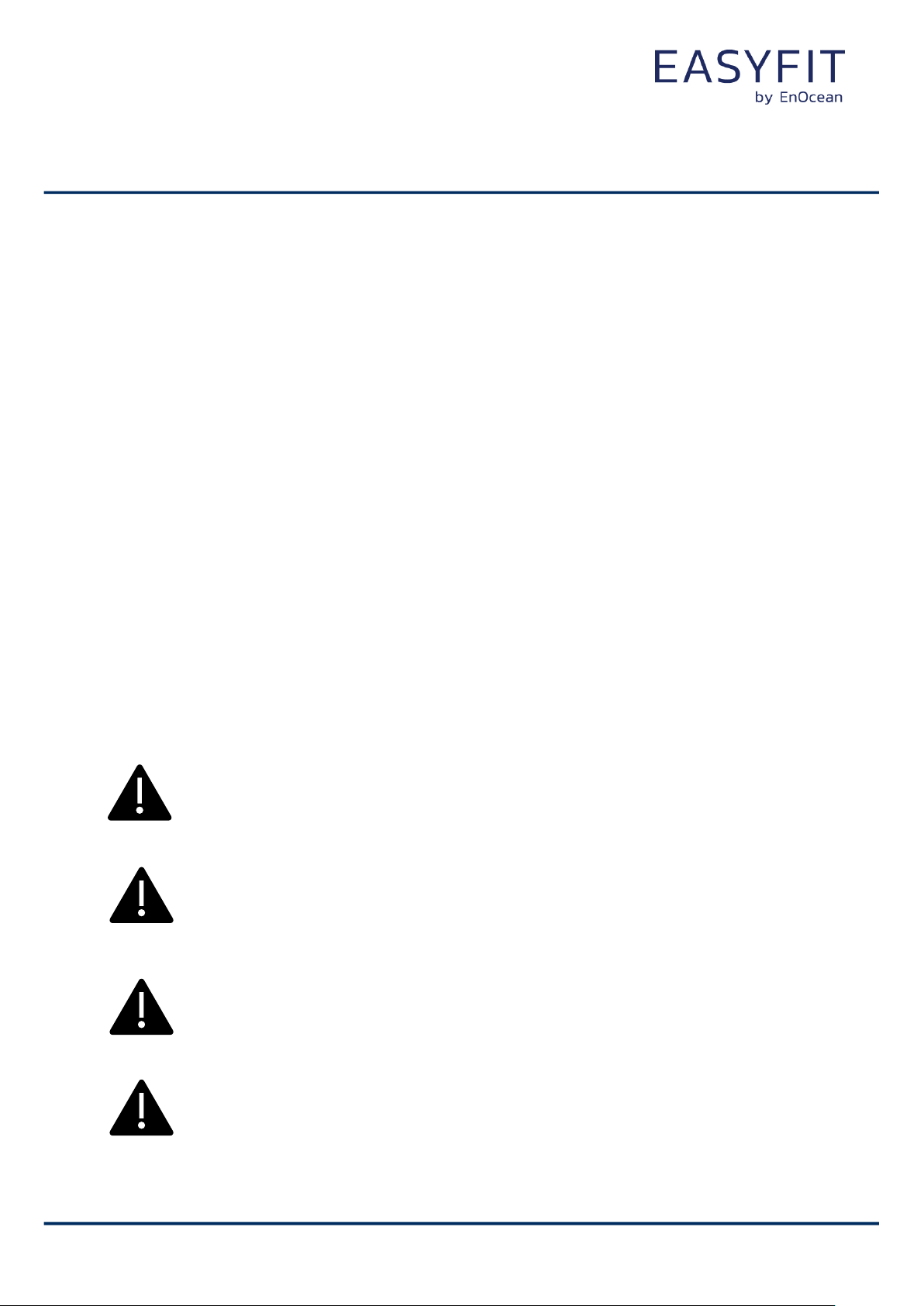
Please familiarize yourself with the following safety remarks before using a backup battery:
Do not insert any tools into the battery slot or the battery ejection slot. Doing so
could create a short circuit or damage the PCB resulting in permanent damage.
CAUTION: Risk of damage or explosion if a battery of incorrect type is used.
This product can contain a coin/button cell battery. If the coin/button cell battery
is swallowed, it can cause severe internal burns in just 2 hours and can lead to
death.
Keep new and used batteries away from children.
Page 24
USER MANUAL
EMDC – ENOCEAN MOTION DETECTOR AND LIGHT LEVEL SENSOR
© 2020 EnOcean | www.enocean.com EMDC User Manual | v1.1 | September 2020 | Page 24/77
4.4 Sensitivity selection switch
The sensitivity selection switch allows reducing the detection range from its default radius of
up to 5 m to a reduced radius of up to 3 m.
Note that the exact detection radius depends on a number of factors including the mounting
height and the ambient temperature.
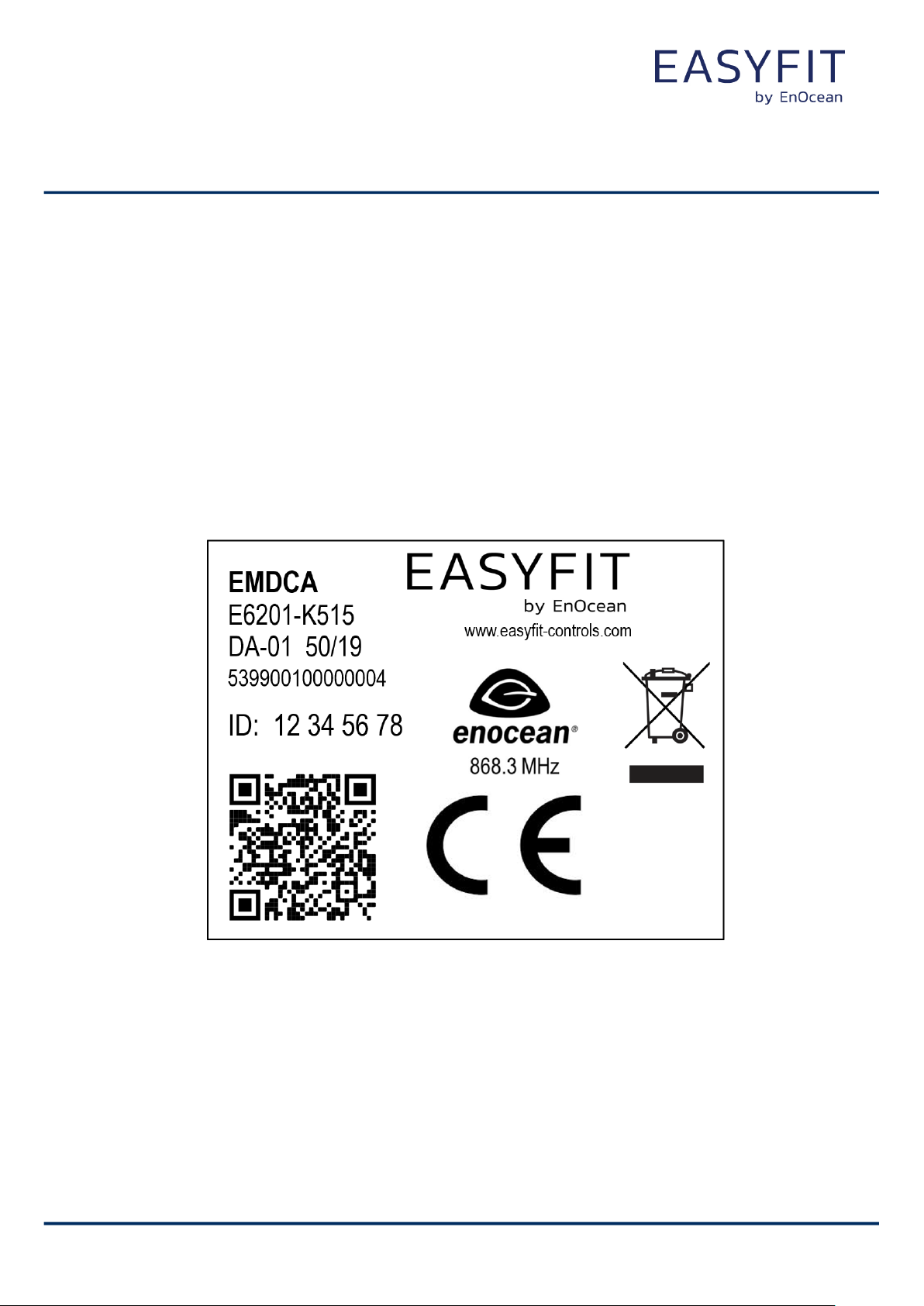
4.5 Device label
Each EDMCx device contains a product label identifying the product revision, the manufacturing date, the frequency and the device radio address. Figure 9 below shows the EMDC
device label for the case of EMDCA (868.3 MHz).
Figure 9 – EMDCA Device Label
The label in this example identifies the following parameters:
◼ Device type: EMDCA
◼ Product Revision: DA-01
◼ Manufacturing Date: Week 50, 2019
◼ Radio address (EURID): 12345678
◼ Operating frequency: 868.3 MHz
In addition to that, the QR code in the bottom left corner that can be used for commissioning
as described in chapter 7.2.
Page 25

USER MANUAL
EMDC – ENOCEAN MOTION DETECTOR AND LIGHT LEVEL SENSOR
© 2020 EnOcean | www.enocean.com EMDC User Manual | v1.1 | September 2020 | Page 25/77
5 Radio communication
EMDC communicates using radio telegrams encoded according to the EnOcean Equipment
Profile (EEP) specification and the EnOcean Alliance Signal Telegram specification on a radio
link according to the EnOcean Alliance Radio Protocol (ERP).
5.1 Radio frame format
EMDCA uses the ERP1 standard (ISO 14543-3-10) while EMDCU and EMDCJ use the ERP2
(ISO 14543-3-11) standard.
Note that EnOcean radio transceivers such as TCM 310 or TCM 515 will convert both ERP1
and ERP2 into the same EnOcean Serial Protocol (ESP3) format so that this difference is
normally not noticeable.
5.1.1 ERP1 frame format
The ERP1 radio frame format is shown in Figure 10 below.
RORG DATA SENDER EURID STATUS CRC
Figure 10 – ERP1 Frame Format
The most relevant fields of the ERP1 frame are the following:
◼ RORG (containing the EEP or SIGNAL RORG)
◼ SENDER EURID (Device address of the sender)
◼ DATA (Telegram payload containing the EEP)
5.1.2 ERP2 frame format
The ERP2 radio frame format is shown in below.
LENGTH HEADER EXT_HEADER SENDER EURID DATA CRC
Figure 11 – ERP2 Frame Format
The most relevant fields of the ERP2 frame are the following:
◼ HEADER (including the EEP or SIGNAL RORG)
◼ SENDER EURID (Device address of the sender)
◼ DATA (Telegram payload containing the EEP)
Page 26

USER MANUAL
EMDC – ENOCEAN MOTION DETECTOR AND LIGHT LEVEL SENSOR
© 2020 EnOcean | www.enocean.com EMDC User Manual | v1.1 | September 2020 | Page 26/77
5.2 EnOcean Equipment Profiles (EEP) and SIGNAL telegrams
The data section within EnOcean radio telegrams uses one of the EnOcean Equipment Profiles (EEP) or one of the SIGNAL telegram types defined by EnOcean Alliance to encode
sensor information. The EEP used is selected by the sender and must be supported by the
receiver.
5.2.1 EEP structure
Each EEP is identified using three fields:
◼ RORG
RORG identifies the high-level telegram type, e.g. rocker switch telegram (RPS), onebyte sensor telegram (1BS), four-byte sensor telegram (4BS), variable length telegram (VLD), Universal Teach-in with EEP (UTE), etc.
◼ FUNC
FUNC identifies the function group to which this telegram belongs, e.g. the function
group of temperature sensors within the four-byte sensor telegram type
◼ VARIANT (or TYPE)
VARIANT (which is confusingly also called TYPE) identifies the exact sensor variant
within the function group, e.g. a 0 °C – 40 °C temperature sensor that is defined
within the function group of temperature sensors
Figure 12 below shows the structure of the EEP identifier.
Figure 12 – EEP identifier structure
The EEP identifier is typically only transmitted during the initial teach-in (paring) between
devices. For special cases (e.g. devices using more than one EEP), data telegrams might
specify the EEP that is used.
Page 27

USER MANUAL
EMDC – ENOCEAN MOTION DETECTOR AND LIGHT LEVEL SENSOR
© 2020 EnOcean | www.enocean.com EMDC User Manual | v1.1 | September 2020 | Page 27/77
5.2.2 4BS telegram structure
4 Byte Sensor (4BS) telegrams are identified by the RORG field being set to 0xA5 which is
followed by four bytes of payload (Bit0 … Bit31).
The payload of 4BS telegrams encodes either the sensor status (4BS Data Telegram) during normal operation or identifies EEP and manufacturer of the device during teach-in (4BS
Teach-in Telegram).
The distinction between data and teach-in telegrams is made based on the status of Bit28.
If this bit is set to 0 then the telegram is a 4BS Teach-in Telegram; if this bit is set to 1
then the telegram is a 4BS Data Telegram.
5.2.3 Signal telegram structure
SIGNAL telegrams are used to encode generic system conditions independent of specific
sensor functionality of the device. Examples of such system conditions are internal energy
level, available ambient energy and backup battery status.
SIGNAL telegrams are identified by having the RORG field of the data telegram set to 0xD0.
After that, the SIGNAL type (what is reported) is identified by the 1 byte long MID field
which is followed by the data corresponding to this SIGNAL type. Figure 13 below shows
the structure of a SIGNAL telegram.
Figure 13 – SIGNAL Telegram Structure
Page 28

USER MANUAL
EMDC – ENOCEAN MOTION DETECTOR AND LIGHT LEVEL SENSOR
© 2020 EnOcean | www.enocean.com EMDC User Manual | v1.1 | September 2020 | Page 28/77
5.2.4 Supported EEP types
EMDC supports a wide range of EEP suitable for different use cases. Table 3 below lists the
supported EEP.
Profile
Type
Reported Parameters
Parameter Range
Size / Resolution
A5-07-01
4BS
Motion Detection Status
Motion Detected
Motion Not Detected
1 Bit
A5-07-03
(Default)
4BS
Motion Detection Status
Motion Detected
Motion Not Detected
1 bit
Light Level
0 … 1000 lx
10 bit
A5-08-01
4BS
Motion Detection Status
Motion Detected
Motion Not Detected
1 bit
Light Level
0 … 510 lx
8 bit
Temperature
0 … 51 °C
8 bit
A5-08-02
4BS
Motion Detection Status
Motion Detected
Motion Not Detected
1bit
Light Level
0 … 1020 lx
8 bit
Temperature
0 … 51 °C
8 bit
A5-08-03
4BS
Motion Detection Status
Motion Detected
Motion Not Detected
1 bit
Light Level
0 … 1530 lx
8 bit
Temperature
-30 … 50 °C
8 bit
Table 3 – Supported EEP types
The default EEP used by EMDC is A5-07-03. It is possible to select a different supported EEP
via the EEP register of the NFC configuration interface described in chapter 9.5.8.
Page 29

USER MANUAL
EMDC – ENOCEAN MOTION DETECTOR AND LIGHT LEVEL SENSOR
© 2020 EnOcean | www.enocean.com EMDC User Manual | v1.1 | September 2020 | Page 29/77
5.2.5 Supported SIGNAL types
Table 4 below lists the SIGNAL types supported by EMDC together with their reported data.
MID
Content
Data
0x06
Energy status (remaining energy)
Enabled by default
1 byte integer value (expressing %)
Valid values: 0 … 100
0x0D
Energy delivery of the harvester
Disabled by default
1 byte Enumeration
Valid values: 0x00 (best) ... 0x04 (worst)
0x10
Backup battery status
Disabled by default
1 byte integer value (expressing %)
Valid values: 0 … 100
Table 4 – Supported SIGNAL Types
The transmission of each supported SIGNAL telegram can be individually enabled and disabled using the via the SIGNAL configuration register of the NFC interface as described in
chapter 9.5.9. By default, the transmission of SIGNAL telegram type 0x06 (energy status)
is enabled while the transmission of SIGNAL telegram type 0x0D (energy delivery) and
0x10 (backup battery status) is disabled.
EMDC will transmit each of the enabled SIGNAL telegram types once for every n EEP (data)
telegrams with n being the configurable transmission interval that can be set via the SIGNAL configuration register of the NFC interface as described in 9.5.9.
The default setting is that one SIGNAL telegram per enabled type (energy status, energy
delivery or backup battery status) will be transmitted every 32 EEP (data) telegrams meaning that the transmission interval is approximately 32 minutes when a room is occupied and
approximately 64 minutes when a room is unoccupied.
If more than one SIGNAL type is enabled, then the individual SIGNAL telegrams will be
transmitted at different times within the selected transmission interval.
Page 30

USER MANUAL
EMDC – ENOCEAN MOTION DETECTOR AND LIGHT LEVEL SENSOR
© 2020 EnOcean | www.enocean.com EMDC User Manual | v1.1 | September 2020 | Page 30/77
6 Security
EMDC supports both standard and high security modes as defined by EnOcean Alliance according to the EnOcean security specification: https://www.enocean-alliance.org/sec/.
6.1 Basic concepts
Security for radio transmission addresses two main issues:
◼ Unauthorized interception (reception and correct interpretation) of transmitted data
In doing so, a third (unauthorized) party is able to understand the content of a received content.
◼ Unauthorized transmission of radio telegrams
In doing so, a third (unauthorized) party is able to transmit a radio telegram that is
treated by a receiver as valid request.
Somewhat loosely speaking, the goal of security has to be preventing an unauthorized person
(often referred to as an Attacker) both from learning about the current state of a system and
from actively changing it.
These goals can be achieved via techniques such as telegram encryption, telegram authorization and dynamic security key modification. All three techniques will be reviewed in the
subsequent chapters for reference.
6.2 Telegram encryption
The goal of telegram encryption is to prevent unauthorized receivers from correctly interpreting the content of a telegram.
In order to do so, the original (plain text) data is encrypted with a key thus transforming it
into encrypted, unreadable data. Only when the correct key is known it is possible to transform – decrypt - the encrypted data into readable data again.
Figure 14 below shows the concept.
Figure 14 – Telegram encryption
Decryption
Decryption Key
Unencrypted Data
(Plain Text)
Encryption
Unencrypted Data
(Plain Text)
Encrypted Data
Encryption Key
Encrypted Data
Page 31

USER MANUAL
EMDC – ENOCEAN MOTION DETECTOR AND LIGHT LEVEL SENSOR
© 2020 EnOcean | www.enocean.com EMDC User Manual | v1.1 | September 2020 | Page 31/77
6.2.1 Telegram authentication
The goal of telegram authentication is to prevent unauthorized senders to transmit apparently
valid commands causing the receiver to perform unauthorized actions.
Telegram authentication works by creating a message signature (often called Cipher-based
Message Authentication Code or CMAC in short) based on the content of the telegram and
the secret key.
Essentially, the telegram data is transformed via a defined algorithm using the secret key
into a unique, fixed size signature which identifies this specific message. EMDC by default
uses a 32 bit value for this signature; a legacy mode of 24 bit is also supported and can be
selected via NFC.
For an optimal signature algorithm, the likelihood of two different messages creating the
same message signature is inversely proportional to the signature size, so for instance for
32 bit signatures the likelihood would be one approximately in 4 billion.
For message authentication purposes, the message signature (CMAC) is typically appended
to the message itself and transmitted together with it.
When the receiver receives such a message, it will itself calculate the CMAC based on the
secret key and the content of the received message. The receiver then compares the CMAC
it calculated with the CMAC it received as part of the message.
If both CMAC are the same, then the receiver can establish two important facts:
1. The message originates from an owner of the secret key
2. The content of the message has not been modified
Figure 15 below illustrates the content authorization via a CMAC signature.
Figure 15 – Telegram authentication
Signature
Calculation
Input Data
Secret Key
Signature
Data
Signature
Data
Signature
Calculation
Secret Key
Compare
OK
Page 32

USER MANUAL
EMDC – ENOCEAN MOTION DETECTOR AND LIGHT LEVEL SENSOR
© 2020 EnOcean | www.enocean.com EMDC User Manual | v1.1 | September 2020 | Page 32/77
6.2.2 Dynamic security key modification
One fundamental problem with both content protection and content authorization is that using the same input data (plain text) with the same key always yields the same encrypted
data and the same signature.
This enables attacks based on monitoring previous system behaviour. If an attacker has
observed that a certain data telegram results in a certain light being turned on then he could
use this information to identify - or even actively send - similar telegrams in the future. This
type of attack is often called Replay Attack since it works by reusing (replaying) previously
used data telegrams.
In order to prevent this type of attack, either the telegram data or the security key must
change to ensure that identical input data does not create identical encrypted radio telegrams. The mechanism used by the transmitter to change the telegram data or the security
key has to be known to the receiver in order to correctly decrypt and authenticate received
data telegrams.
The change of telegram data or security key is typically ensured by means of monotonously
incrementing counters (often called Rolling Code or RLC in short).
The value of such counter is then used to either modify the telegram payload (usually by
appending it to the payload) or the security key. EnOcean systems use the latter approach.
Figure 16 below illustrates the concept of dynamic key modification used by EnOcean radio
systems.
Figure 16 – Dynamic security key modification
Decryption
Dynamic Key
Unencrypted Data
(Plain Text)
Encryption
Unencrypted Data
(Plain Text)
Encrypted Data
Dynamic Key
Encrypted Data
Secret Key
Incrementing
Counter
Secret Key
Incrementing
Counter
Data Valid?
NO
YES
Page 33

USER MANUAL
EMDC – ENOCEAN MOTION DETECTOR AND LIGHT LEVEL SENSOR
© 2020 EnOcean | www.enocean.com EMDC User Manual | v1.1 | September 2020 | Page 33/77
6.3 Security parameters
The following security parameters are used to define secure communication based on
EnOcean Alliance security specification between a sender and a receiver:
◼ EURID (Device ID of the sender)
◼ Rolling code size and current value
◼ Signature (MAC) size
◼ Security algorithm
Those parameters are communicated from EMDC to the receiver during teach-in either via a
secure teach-in telegram, via NFC configuration or via the QR code of EMDC.
6.3.1 EURID
The EURID identifies the sender of each radio telegram using a unique 6 byte value. The
EURID of an EnOcean device is assigned at manufacturing and cannot be changed.
6.3.2 Security key
The security key is a random 128 Bit (16 byte) value that is known only to the sender and
the receiver(s). It is used to encrypt, decrypt and authenticate telegrams.
6.3.3 Rolling code
The rolling code is a monotonously incrementing counter used to modify the encryption key
of secure telegrams as described in chapter 6.2.2. The rolling code is generated by the sender
and monitored by the receiver. EMDC uses by default a 32 bit rolling code counter which will
be initialized to 0 at the time of production and increment whenever a telegram is transmitted.
The receiver will store the most recently received rolling code value and only accept telegrams with higher rolling code values to avoid retransmission of previously transmitted messages.
6.3.4 Security algorithm
EMDC uses variable AES based on AES-128 to encrypt and authenticate its telegrams.
Page 34

USER MANUAL
EMDC – ENOCEAN MOTION DETECTOR AND LIGHT LEVEL SENSOR
© 2020 EnOcean | www.enocean.com EMDC User Manual | v1.1 | September 2020 | Page 34/77
6.4 Secure teach-in telegram
Teach-in is the process by which EMDC communicates to a remote device all parameters
required to establish secure communication using a radio telegram with a specific payload.
This radio telegram is called a secure teach-in telegram (abbreviated SEC_TI).
The parameters communicated in such secure teach-in telegram are the following:
◼ RORG (1 byte)
Secure teach-in telegrams are identified by the RORG 0x35
◼ Teach-in Info (1 byte)
This field is used for the segmentation and reassembly process and also defines the
teach-in type (which is always uni-directional for EMDC). The first telegram has this
field set to 0x20 while the second telegram has this field set to 0x40.
◼ Security Level (1 byte)
The security level specifies the type of encryption and authentication used by for the
communication with the remote device as described below.
◼ Rolling Code (4 byte in default configuration)
The rolling code is used to constantly modify the security key to avoid message replay.
The rolling code is initialized to 0 at the time of production and increases for each
transmission of a secure telegram. EMDC uses 4 byte rolling code length by default
but supports also a legacy mode with 3 byte rolling code.
◼ Security key (16 byte)
The 128 bit AES security key is used in high security mode to encode and / or authenticate radio telegrams
The length of a secure teach-in telegram exceeds the maximum telegram length of EnOcean
radio telegrams; therefore the telegram will be split (fragmented) into two individual telegrams and reassembled at the receiver.
Figure 17 below shows the first of the two telegrams for the case of the default configuration.
Figure 17 – Secure teach-in telegram structure (first telegram)
The structure for the second of the two telegrams is shown in Figure 18 below.
Figure 18 – Secure teach-in telegram structure (second telegram)
Page 35

USER MANUAL
EMDC – ENOCEAN MOTION DETECTOR AND LIGHT LEVEL SENSOR
© 2020 EnOcean | www.enocean.com EMDC User Manual | v1.1 | September 2020 | Page 35/77
6.4.1 Security level format (SLF)
The security level format (SLF) defines the security parameters used for communication between two devices. Figure 19 below shows the supported security parameters options encoded in the SLF field.
7 6 5 4 3 2 1
0
RLC_MODE
CMAC_SIZE
ENCRYPTION_ALGO
0b000: No RLC algorithm
0b001: RFU
0b010: 16 bit RLC (not transmitted)
0b011: 16 bit RLC (16 bit transmitted)
0b100: 24 bit RLC (not transmitted)
0b101: 24 bit RLC (24 bit transmitted)
0b110: 32 bit RLC (24 bit transmitted)
0b111: 32 bit RLC (32 bit transmitted)
0b00: No MAC
0b01: 24 bit CMAC
0b10: 32 bit CMAC
0b11: RFU
0b000: No data encryption
0b001: Deprecated
0b010: Deprecated
0b011: VAES using AES128
0b100: AES-CBC using AES128
Others: RFU
Figure 19 – SLF structure
6.5 EMDC security implementation
EMDC supports both standard and high security modes as defined by EnOcean Alliance. The
security mode can be selected both via the LRN button and via the NFC interface.
For high security mode, the default security level format (SLF) is set to use a 32 bit sequence counter to generate a 32 bit signature using VAES (AES-128) as algorithm.
The security level format for this mode is 0xF3.
For backwards compatibility with legacy systems, EMDC provides the option to use 24 bit
RLC with 24 bit CMAC using VAES (AES-128) as algorithm. The security level format for
that mode is 0xAB.
The switch between default and legacy security mode is done using the SECURITY_MODE
register of the NFC interface as described in chapter 9.5.7.
Page 36

USER MANUAL
EMDC – ENOCEAN MOTION DETECTOR AND LIGHT LEVEL SENSOR
© 2020 EnOcean | www.enocean.com EMDC User Manual | v1.1 | September 2020 | Page 36/77
7 EMDC commissioning
Commissioning is the process by which EMDC is learned into a receiver (actuator, controller,
gateway, etc.).
The following two tasks are required in this process:
◼ Device identification
The receiver needs to know how to uniquely identify this specific EMDC device. This
is achieved by using a unique 48 Bit ID (Source Address) for each EMDC device.
◼ EnOcean Equipment Profile (EEP) identification
The receiver needs to know which EnOcean Equipment Profile (EEP) is used by
EMDC to encode parameters within a data telegram
◼ Security parameter exchange
The receiver needs to be able to authenticate radio telegrams from EMDC in order to
ensure that they originate from this specific device and have not been modified. This
is achieved by exchanging a 128 bit random security key used by EMDC to authenticate its radio telegrams.
EMDC provides the following options for these tasks:
◼ Radio-based commissioning (LRN Telegram)
EMDC can communicate its parameters via secure teach-in telegrams as described
in chapter 6.4 to the intended receiver. Transmission of such telegrams can be triggered by using the LRN button or via NFC.
◼ QR code commissioning
Each EMDC device contains a product label with an optically readable Quick Response (QR) Code as described in chapter 4.5.
The QR code identifies the EURID and the security key used by EMDC and can be
read by a by a suitable commissioning tool (e.g. smartphone) which is already part
of the network into which EMDC will be commissioned.
The commissioning tool then communicates these parameters together with information about the selected EEP to the intended receiver of EMDC radio telegrams.
◼ NFC commissioning
Each EMDC device contains an NFC interface allowing to read device parameters and
to configure the device.
Page 37

USER MANUAL
EMDC – ENOCEAN MOTION DETECTOR AND LIGHT LEVEL SENSOR
© 2020 EnOcean | www.enocean.com EMDC User Manual | v1.1 | September 2020 | Page 37/77
7.1 Radio-based commissioning
Radio-based commissioning is used to associate EMDC with other devices by sending a dedicated radio telegram (a so-called commissioning telegram).
To do so, EMDC can transmit a dedicated commissioning telegram identifying its relevant
parameters according to EnOcean Alliance standard. The transmission of the commissioning
telegram is triggered by pressing the LRN button.
Radio-based commissioning mode is intended for applications where NFC commissioning cannot be used. Radio-based commissioning can be disabled via NFC.
7.2 QR code commissioning
Each EMDC device contains a product label which can be used to commission EMDC via its
commissioning QR code. See chapter 4.5 for a description of the product label.
7.2.1 Commissioning QR code structure
Each device label contains a commissioning QR code that can be scanned to identify source
address and security key of EMDC to a receiver. Figure 20 shows an example of such QR
code.
Figure 20 – EMDC Commissioning QR code
Note that the EnOcean Equipment Profile used by EMDC has to be communicated to the re-
ceiver as well. See chapter 5.2.4 for a description of the supported EEP.
Page 38

USER MANUAL
EMDC – ENOCEAN MOTION DETECTOR AND LIGHT LEVEL SENSOR
© 2020 EnOcean | www.enocean.com EMDC User Manual | v1.1 | September 2020 | Page 38/77
7.2.2 Commissioning QR code format
The QR code used in the new product label encodes the product parameter according to the
ANSI/MH10.8.2-2013 industry standard. The QR code shown in Figure 20 above encodes the
following string:
30S000012345678+Z9E0DE9C25386B6C4F070642E19E03680+30PE6201-K515+2PDA01+S012345567890123
Table 5 below describes the ANSI/MH10.8.2 data identifiers used by the EMDC device label
and shows the interpretation of the data therein.
Identifier
Length of data (excluding identifier)
Value
30S
12 characters
Device Address EURID (hex)
Z
32 characters
Security Key (hex)
30P
10 characters
Ordering Code (E6201-K515)
2P
4 characters
Step Code - Revision (DA-01)
S
14 characters
Serial Number
Table 5 – QR code format
7.3 Commissioning via NFC interface
EMDC implements NFC Forum Type 2 Tag functionality as specified in the ISO/IEC 14443
Part 2 and 3 standards. This NFC functionality can be used to read the device address and
the security key of EMDC as described in chapter 9.5.
Page 39

USER MANUAL
EMDC – ENOCEAN MOTION DETECTOR AND LIGHT LEVEL SENSOR
© 2020 EnOcean | www.enocean.com EMDC User Manual | v1.1 | September 2020 | Page 39/77
8 NFC interface
EMDC implements an NFC configuration interface that can be used to access (read and
write) the EMDC configuration memory and thereby configure the device as described in
the following chapters.
NFC communication distance is for security reasons set to require direct contact between
the NFC reader and the EMDC device.
Note that EMDC temporarily stops operation while the NFC reader is actively connected to
the NFC interface of EMDC. EMDC operation will automatically resume operation once the
NFC reader has been disconnected.
8.1 NFC interface parameters
The NFC interface of EMDC uses NFC Forum Type 2 Tag functionality as specified in the
ISO/IEC 14443 Part 2 and 3 standards. It is implemented using an NXP NT3H2111 Mifare
Ultralight tag.
8.2 NFC access protection
Protected data access is only possible after unlocking the configuration memory with the
correct 32 bit PIN code. By default, the protected area is locked and the default pin code for
unlocking access is 0x0000E500.
The default pin code shall be changed to a user-defined value as part of the installation
process. This can be done by unlocking the NFC interface with the old PIN code and then
writing the new PIN code to page 0x4B.
Page 40

USER MANUAL
EMDC – ENOCEAN MOTION DETECTOR AND LIGHT LEVEL SENSOR
© 2020 EnOcean | www.enocean.com EMDC User Manual | v1.1 | September 2020 | Page 40/77
8.3 Using the NFC interface
Using the NFC interface requires the following:
◼ NFC reader
This can be either a USB NFC reader connected to a PC or a suitable smartphone with
NFC functionality
◼ NFC SW with read, write, PIN lock, PIN unlock and PIN change functionality
This can be either a PC application or an Android / iOS app
These options are described in more detail below.
8.3.1 PC with dedicated NFC reader
For PC-based applications, EnOcean recommends the TWN4 Multitech 2 HF NFC Reader (order code T4BT-FB2BEL2-SIMPL) from Elatec RFID Systems (sales-rfid@elatec.com).
This reader is shown in Figure 21 below.
Figure 21 – Elatec TWN4 MultiTech Desktop NFC Reader with CDC interface
8.3.2 Smartphones with NFC
NFC functionality is available in certain Android (e.g. Samsung Galaxy S7 / S8 / S9 / S10)
and iOS (iPhone7 or newer, firmware version 13 or newer) smartphones.
EnOcean provides the configuration app “EnOcean Tool” for these devices which can be
downloaded directly from the respective app store.
At the time of writing, the tool was available from the Google Play Store using this link:
https://play.google.com/store/apps/details?id=de.enocean.easytool&hl=en
Likewise, the tool was available from the Apple Store using this link:
https://apps.apple.com/de/app/enocean-tool/id1497283202
Page 41

USER MANUAL
EMDC – ENOCEAN MOTION DETECTOR AND LIGHT LEVEL SENSOR
© 2020 EnOcean | www.enocean.com EMDC User Manual | v1.1 | September 2020 | Page 41/77
8.4 NFC interface functions
For a detailed description about the NFC functionality, please refer to the ISO/IEC 14443
standard.
For specific implementation aspects related to the NXP implementation in NT3H2111,
please refer to the NXP documentation which at the time of writing was available under this
link:
https://www.nxp.com/docs/en/data-sheet/NT3H2111_2211.pdf
The following chapters summarize the different functions for reference purposes.
8.4.1 NFC interface state machine
Figure 22 below shows the overall state machine of the NFC interface.
Figure 22 – NFC interface state machine
Page 42

USER MANUAL
EMDC – ENOCEAN MOTION DETECTOR AND LIGHT LEVEL SENSOR
© 2020 EnOcean | www.enocean.com EMDC User Manual | v1.1 | September 2020 | Page 42/77
8.4.2 IDLE state
IDLE is the waiting state after a Power-On Reset (POR), i.e. after the NFC tag has been introduced into the magnetic field of the NFC reader.
The NFC tag exits the IDLE state towards the READY 1 state when either a REQA or a WUPA
command is received from the NFC reader. REQA and WUPA commands are transmitted by
the NFC reader to determine whether any cards are present within its working range.
Any other data received by the NFC tag while in IDLE state is discarded and the NFC tag
will remain in IDLE state.
8.4.3 READY 1 state
READY 1 is the first UID resolving state where the NFC tag resolves the first 3 bytes of the
7 byte UID using the ANTICOLLISION or SELECT commands for cascade level 1.
READY 1 state is exited after the SELECT command from cascade level 1 with the matching
complete first part of the UID has been executed. The NFC tag then proceeds into READY 2
state where the second part of the UID is resolved.
8.4.4 READY 2 state
READY 2 is the second UID resolving state where the NFC tag resolves the remaining 4
bytes of the 7 byte UID using the ANTICOLLISION or SELECT commands for cascade level
2.
READY 2 state is exited after the SELECT command from cascade level 2 with the matching
complete part of the UID has been executed. The NFC tag then proceeds into ACTIVE state
where the application-related commands can be executed.
8.4.5 ACTIVE state
ACTIVE state enables read and write accesses to unprotected memory.
If access to protected memory is required then the tag can transition from the ACTIVE state
to AUTHENTICATED state by executing the PWD_AUTH command in conjunction with the
correct 32 bit password.
Page 43

USER MANUAL
EMDC – ENOCEAN MOTION DETECTOR AND LIGHT LEVEL SENSOR
© 2020 EnOcean | www.enocean.com EMDC User Manual | v1.1 | September 2020 | Page 43/77
8.4.6 Read command
The READ command requires a start page address, and returns the 16 bytes of four
NFC tag pages (where each page is 4 byte in size).
For example, if the specified address is 03h then pages 03h, 04h, 05h, 06h are returned. Special conditions apply if the READ command address is near the end of the accessible
memory area.
Figure 23 below shows the read command sequence.
Figure 23 – NFC read command sequence
8.4.7 Write command
The WRITE command requires a start page address and returns writes 4 bytes of data into
that page.
Figure 24 below shows the read command sequence.
Figure 24 – NFC write command sequence
Page 44

USER MANUAL
EMDC – ENOCEAN MOTION DETECTOR AND LIGHT LEVEL SENSOR
© 2020 EnOcean | www.enocean.com EMDC User Manual | v1.1 | September 2020 | Page 44/77
8.4.8 Password authentication (PWD_AUTH) command
The protected memory area can be accessed only after successful password verification
via the PWD_AUTH command.
The PWD_AUTH command takes the password as parameter and, if successful, returns the
password authentication acknowledge, PACK.
Figure 25 below shows the password authentication sequence.
Figure 25 – Password authentication sequence
Page 45

USER MANUAL
EMDC – ENOCEAN MOTION DETECTOR AND LIGHT LEVEL SENSOR
© 2020 EnOcean | www.enocean.com EMDC User Manual | v1.1 | September 2020 | Page 45/77
9 NFC registers
The NFC memory is organized in pages (smallest addressable unit) where each page contains
4 byte of data. Several pages with similar functionality form a NFC memory area.
9.1 NFC memory areas
These NFC pages are allocated into the following areas:
◼ PRODUCT NDEF string (Public read-only access; no PIN required)
This area contains an NDEF string identifying key device parameters
◼ USER NDEF string (Public read / write access; no PIN required)
This area allows any user to read or write information about the device such as the
intended installation location or additional instructions
◼ PUBLIC INFO (Public read-only access; no PIN required)
This area contains key device parameters in binary format
◼ NFC HEADER (Public read-only access; no PIN required)
This area contains information about the NFC revision
◼ INTERNAL DATA (Non-accessible)
This area contains calibration values and internal parameters and cannot be used
◼ CONFIGURATION (Read and Write access, PIN required)
This area contains device configuration registers
◼ USER DATA (Read and Write access, PIN required)
This area allows the user to store up to 64 byte of data such as information about the
installation or any other data that the user deems relevant.
EMDC does not use this area and does not interpret its content in any way.
The organization of the EMDC NFC memory map is shown in Table 6 below.
NFC Address
Memory Area
Content
0x00 … 0x1D
PRODUCT NDEF
Device identification NDEF string (read-only)
0x1E … 0x30
USER NDEF
User information NDEF string (read / write access)
0x31 … 0x33
NFC HEADER
NFC memory revision (read-only)
0x34 … 0x3F
INTERNAL DATA
Internal data (Do not use)
0x40 … 0x54
CONFIGURATION
Configuration registers (Read / Write, PIN protected)
0x55 … 0xCF
INTERNAL DATA
Internal data (Do not use)
0xD0 … 0xDF
USER DATA
User data (64 byte read / write access, PIN protected)
0xE0 … 0xEB
INTERNAL DATA
Internal data (Do not use)
Table 6 – EMDC NFC memory areas
Page 46

USER MANUAL
EMDC – ENOCEAN MOTION DETECTOR AND LIGHT LEVEL SENSOR
© 2020 EnOcean | www.enocean.com EMDC User Manual | v1.1 | September 2020 | Page 46/77
9.2 PRODUCT NDEF
The PRODUCT NDEF area contains a device identification string using the NDEF (NFC Data
Exchange Format) standard that is readable by most NFC-capable reader devices (including
smartphones).
An example device identification string from the NDEF area of EMDC could be:
6PENO+30S000012345678+1P000B0000004C+30PS6221-K516+2PDA04+12Z01234567891234
+3C31+16S01000000
This NDEF string encodes the parameters shown in Table 7 below.
Identifier
Length of data (excl. identifier)
Value
6P
3 characters
Standard: “ENO”
30S
12 characters
EURID (6 byte, variable)
1P
12 characters
EnOcean Alliance Product ID
STM 550: „000B0000004C“
STM 550U: „000B0000004D“
STM 550J: „000B0000004E“
30P
10 characters
Ordering Code
STM 550: “S6201-K516”
STM 550U: “S6251-K516”
STM 550J: “S6261-K516”
2P
4 characters
Step Code and Revision (“DA04”)
12Z
14 characters
NFC UID (14 byte, globally unique)
3C
2 characters
Header Start Address (“31” = 0x31)
16S
8 characters
SW Version
Example: 01000000 = 01.00.00.00
Table 7 – NDEF Parameters
9.3 USER NDEF
The USER NDEF area allows the user to store a string of up to 64 characters starting at
page 0x20 and ending at page 0x2F. The remaining pages in this area (0x1E, 0x1F, 0x30)
provide the required NDEF formatting information and cannot be changed by the user.
Page 47

USER MANUAL
EMDC – ENOCEAN MOTION DETECTOR AND LIGHT LEVEL SENSOR
© 2020 EnOcean | www.enocean.com EMDC User Manual | v1.1 | September 2020 | Page 47/77
9.4 NFC HEADER
The NFC HEADER area contains information about the NFC memory structure and can
therefore be used to distinguish between different NFC memory layouts.
9.4.1 NFC HEADER area structure
The structure of the NFC HEADER area is shown in Figure 26 below.
NFC Address
Content
Byte 0
Byte 1
Byte 2
Byte 3
0x31
START (0xE0)
LENGTH (0x0A)
VERSION (0x01)
OEM MSB (0x00)
0x32
OEM LSB (0x0B)
DEVICE_IDENTIFIER (0x000002)
0x33
REVISION (0x03)
END (0xFE)
UNUSED (0x0000)
Figure 26 – NFC HEADER area structure
The NFC HEADER contains the following fields:
◼ START
This field identifies the start of the NFC header and is always set to 0xE0
◼ LENGTH
This field identifies the length of the NFC header.
For EMDC, this field is set to 0x0A since the header structure is 10 bytes long
◼ VERSION
This field identifies the major revision and is set to 0x01 currently
◼ OEM
The 16 bit OEM field identifies the manufacturer of the device so that manufacturerspecific layout implementations can be determined.
For EnOcean GmbH this field is set to 0x000B
◼ DEVICE_IDENTIFIER
The 24 bit DEVICE_IDENTIFIER field identifies an individual device from the range
of devices manufactured by the manufacturer specified in the OEM field.
For EMDC, the DEVICE_IDENTIFIER is set to 0x000002
◼ REVISION
The REVISION field identifies the exact revision of the NFC layout. This REVISION
will be incremented whenever a change to the NFC layout is made.
◼ END
The END field identifies the end of the NFC header and is always set to 0xFE. The
number of bytes from START to END must equal LENGTH, otherwise the NFC
header is invalid.
Page 48

USER MANUAL
EMDC – ENOCEAN MOTION DETECTOR AND LIGHT LEVEL SENSOR
© 2020 EnOcean | www.enocean.com EMDC User Manual | v1.1 | September 2020 | Page 48/77
9.5 CONFIGURATION
The CONFIGURATION area allows configuring the device parameters and is therefore the
most important part of the NFC memory. Configuration registers larger than 8 bit use big
endian format, i.e. the most significant byte comes first.
Read or write access to the CONFIGURATION area is only possible after issuing a
PWD_AUTH command as described in chapter 8.4.8 using the correct 32 bit PIN code.
9.5.1 Using the NFC configuration functionality
Before making any changes to the default configuration, be sure to familiarize yourself with
the functionality of the device and the effect of the intended changes. EMDC will not accept
the setting of non-valid values for its parameters. If any parameter is non-valid then all
changes made will be rejected and the previous configuration will be restored.
9.5.2 CONFIGURATION area structure
The structure of the CONFIGURATION area is shown in Figure 27 below.
NFC
Address
Content
Byte 0
Byte 1
Byte 2
Byte 3
0x40
PRODUCT_ID (as characters in ASCII format)
Will be copied to NDEF Header
0x41
0x42
0x43
RFU
0x44
…
0x47
USER_KEY (128 Bit)
(Write Only - Will be reset to zero after it has been copied to internal memory)
Can be used as alternative security key instead of FACTORY_KEY
0x48
SECURITY_KEY_MODE
SECURITY_CFG
RFU
0x49
EEP
SIGNAL
LED_MODE
FUNCTIONAL_MODE
0x4A
STANDARD_TX_INTERVAL
OCCUPIED_TX_INTERVAL
0x4B
NFC_PIN_CODE
0x4C
THRESHOLD_CFG
RFU
LIGHT_SENSOR_CFG
TEMP_SENSOR_CFG
0x4D
SOLAR_ THRESHOLD
SOLAR_ TX_INTERVAL
0x4E
LIGHT_THRESHOLD
LIGHT_ TX_INTERVAL
0x4F
RFU
…
0x53
0x54
AMBIENT_LIGHT_TEST_RESULT
RFU
Figure 27 – CONFIGURATION area structure
Page 49

USER MANUAL
EMDC – ENOCEAN MOTION DETECTOR AND LIGHT LEVEL SENSOR
© 2020 EnOcean | www.enocean.com EMDC User Manual | v1.1 | September 2020 | Page 49/77
9.5.3 NFC_PIN_CODE
The PIN code used to protect access to the NFC CONFIGURATION memory area should be
changed from the default value to a user-specific value to avoid unauthorized access to the
device configuration.
To do so, first authenticate with the current PIN code and then write the new PIN code (32
bit value) to the NFC_PIN_CODE register.
9.5.4 PRODUCT_ID
The EnOcean Alliance Product ID uniquely identifies each product within the EnOcean Alliance ecosystem. The Product ID consists of a 2 byte manufacturer identification code (assigned by EnOcean Alliance) and a 4 byte product identification code (assigned by the manufacturer.
EnOcean has been assigned the manufacturer identification code 0x000B. EnOcean has assigned the following product identification codes to EMDC:
EMDCA: 0000004F
EMDCU: 00000050
EMDCJ: 00000051
The PRODUCT_ID register contains the Product ID in ASCII format (12 characters) and allows changing both manufacturer and product identification. Changing the PRODUCT_ID
will also cause the PRODUCT ID field in the NDEF string (described in chapter 9.2) to be updated.
Figure 28 below shows the structure of the PRODUCT_ID register.
PRODUCT_ID
CH0
CH1
CH2
CH3
CH4
CH5
CH6
CH7
CH8
CH9
CH10
CH11
Manufacturer (“000B”)
Product ID (“0000004F”, “00000050” or “00000051”)
Figure 28 – PRODUCT_ID
Page 50

USER MANUAL
EMDC – ENOCEAN MOTION DETECTOR AND LIGHT LEVEL SENSOR
© 2020 EnOcean | www.enocean.com EMDC User Manual | v1.1 | September 2020 | Page 50/77
9.5.5 USER_KEY
Each EMDC module is pre-programmed at the factory with a randomly generated 128 bit
security key (FACTORY_KEY). This key will by default be used to encrypt and authenticate
EMDC radio telegrams when operating in high security mode.
In certain applications it might be desirable to assign a different (user-defined) security key
(USER_KEY) during commissioning to EMDC. This can be done by writing the user-defined
security key to the USER_KEY register and setting KEY SELECTION field of the SECURITY_KEY_MODE to 0b01 as described below.
Note that the USER_SECURITY_KEY register is a write-only register meaning that it is not
possible to read back a user-defined security key.
9.5.6 SECURITY_KEY_MODE
The register SECURITY_KEY_MODE allows selecting if FACTORY_KEY or USER_KEY should
be used to encrypt and authenticate EMDC radio telegrams in high security mode. In addition, it allows disabling the transmission of Secure Teach-in telegrams in order to protecting
the security key.
Note that if the transmission of a secure teach-in telegram has been disabled and is subsequently re-enabled then USER_KEY will be reset to FACTORY_KEY.
Figure 29 below shows the structure of the SECURITY_KEY_MODE register.
SECURITY_KEY_MODE (Default: 0x00)
Bit 7
Bit 6
Bit 5
Bit 4
Bit 3
Bit 2
Bit 1
Bit 0
RFU
SECURE LRN TELEGRAM
KEY SELECTION
Figure 29 – SECURITY_KEY_MODE register
The encoding for the KEY SELECTION bit field is shown in Table 8 below.
KEY SELECTION
Security key used
0b00 (Default)
FACTORY_KEY is used
0b01
USER_KEY is used
0b10, 0b11
Reserved, do not use
Table 8 – KEY SELECTION bit field encoding
Page 51

USER MANUAL
EMDC – ENOCEAN MOTION DETECTOR AND LIGHT LEVEL SENSOR
© 2020 EnOcean | www.enocean.com EMDC User Manual | v1.1 | September 2020 | Page 51/77
The encoding for the SECURE LRN TELEGRAM bit field is shown in Table 9 below.
SECURE LRN TELEGRAM
Secure LRN telegram
0b00 (Default)
Secure LRN Telegram (containing security key) enabled
0b01
Secure LRN Telegram (containing security key) disabled
0b10, 0b11
Reserved, do not use
Table 9 – SECURE LRN TELEGRAM bit field encoding
9.5.7 SECURITY_MODE
The register SECURITY_MODE identifies the security settings used by EMDC. Figure 30 below shows the structure of the SECURITY_MODE register.
SECURITY_MODE (Default: 0x00)
Bit 7
Bit 6
Bit 5
Bit 4
Bit 3
Bit 2
Bit 1
Bit 0
RFU
SECURITY FORMAT
SECURITY MODE
Figure 30 – SECURITY_MODE register
The encoding for the SECURITY MODE bit field is shown in Table 10 below.
SECURITY MODE
Security Mode
0b00 (Default)
Standard, can be changed by the user with the LRN button
0b01
High Security, can be changed by the user with the LRN button
0b10
Standard, cannot be changed by the user with the LRN button
0b11
High Security, cannot be changed by the user with the LRN button
Table 10 – SECURITY MODE bit field encoding
The encoding for the SECURITY FORMAT bit field is shown in Table 11 below.
SECURITY FORMAT
Advertising Interval
0b00 (Default)
32 bit RLC and 32 bit CMAC
0b01
24 bit RLC and 24 bit CMAC
0b10, 0b11
Reserved, do not use
Table 11 – SECURITY FORMAT bit field encoding
Page 52

USER MANUAL
EMDC – ENOCEAN MOTION DETECTOR AND LIGHT LEVEL SENSOR
© 2020 EnOcean | www.enocean.com EMDC User Manual | v1.1 | September 2020 | Page 52/77
9.5.8 EEP
The EEP register determines the EnOcean Equipment Profile (EEP) used by EMDC for the
transmission of data telegrams. Figure 31 below shows the structure of the EEP register.
EEP (Default: 0x00)
Bit 7
Bit 6
Bit 5
Bit 4
Bit 3
Bit 2
Bit 1
Bit 0
RFU
EEP
Figure 31 – EEP register
The encoding used by the SIZE bit field is shown in Table 12 below.
EEP
EnOcean Equipment Profile
0b0000 (Default)
A5-07-03
0b0001
A5-07-01
0b0010
A5-08-01
0b0011
A5-08-02
0b0100
A5-08-03
Others
Reserved, do not use
Table 12 – EEP bit field encoding
Page 53

USER MANUAL
EMDC – ENOCEAN MOTION DETECTOR AND LIGHT LEVEL SENSOR
© 2020 EnOcean | www.enocean.com EMDC User Manual | v1.1 | September 2020 | Page 53/77
9.5.9 SIGNAL
EMDC supports reporting its energy status, the current energy delivery of the harvester and
the backup battery status via SIGNAL telegrams as described in chapter 5.2.
The type and the transmission rate of SIGNAL telegrams are controlled by the SIGNAL register shown in Figure 32 below.
SIGNAL (Default: 0x31)
Bit 7
Bit 6
Bit 5
Bit 4
Bit 3
Bit 2
Bit 1
Bit 0
TRANSMISSION RATE
RFU
BACKUP
BATTERY
ENERGY
DELIVERY
ENERGY
STATUS
Figure 32 – SIGNAL register
EMDC supports the following SIGNAL types:
◼ ENERGY STATUS (MID 0x06)
◼ ENERGY DELIVERY (MID 0x0D)
◼ BACKUP BATTERY STATUS (MID 0x10)
Transmission of these supported SIGNAL types can be enabled by setting the associated
configuration bit in the SIGNAL register to 0b1 and disabled by setting the associated configuration bit to 0b0.
By default, the reporting of the energy status (MID 0x06) is enabled while the reporting of
energy delivery (MID 0x0D) and backup battery status (MID 0x10) is disabled.
EMDC allows additionally to configure at what rate each enabled SIGNAL telegram will be
sent using the TRANSMISSION RATE bit field as shown in Table 13 below. If more than one
SIGNAL telegram is enabled, then this rate will apply to all enabled telegrams. The SIGNAL
telegrams will be transmitted at different times (i.e. not all at the same time one after another) in that case.
TRANSMISSION RATE
Transmission rate for SIGNAL telegrams
0b0000
One SIGNAL telegram every 8 data telegrams
0b0001
One SIGNAL telegram every 16 data telegrams
0b0010
One SIGNAL telegram every 24 data telegrams
0b0011 (Default)
One SIGNAL telegram every 32 data telegrams
…
0b1111
One SIGNAL telegram every 128 data telegrams
Table 13 – TRANSMISSION RATE bit field encoding
Page 54

USER MANUAL
EMDC – ENOCEAN MOTION DETECTOR AND LIGHT LEVEL SENSOR
© 2020 EnOcean | www.enocean.com EMDC User Manual | v1.1 | September 2020 | Page 54/77
9.5.10 LED_MODE
The LED_MODE register determines the brightness of the LED. Figure 33 below shows the
structure of the LED_MODE register.
LED_MODE (Default: 0x02)
Bit 7
Bit 6
Bit 5
Bit 4
Bit 3
Bit 2
Bit 1
Bit 0
RFU
LED
Figure 33 – LED_MODE register
The encoding used by the LED bit field is shown in Table 14 below.
LED
LED Intensity
0b00
OFF
0b01
Low
0b10 (Default)
Medium
0b11
High
Table 14 – LED bit field encoding
Page 55

USER MANUAL
EMDC – ENOCEAN MOTION DETECTOR AND LIGHT LEVEL SENSOR
© 2020 EnOcean | www.enocean.com EMDC User Manual | v1.1 | September 2020 | Page 55/77
9.5.11 FUNCTIONAL_MODE
The FUNCTIONAL_MODE register can be used to switch between the different operation
modes of EMDC as described in chapter 2.5.
Figure 34 below shows the structure of the FUNCTIONAL_MODE register.
FUNCTIONAL_MODE (Default: 0x00, OOB: 0x01)
Bit 7
Bit 6
Bit 5
Bit 4
Bit 3
Bit 2
Bit 1
Bit 0
RFU
MODE
Figure 34 – FUNCTIONAL_MODE register
The encoding used by the MODE bit field is shown in Table 15 below.
MODE
Functional Mode
0b0000 (Default)
Standard Operation Mode
0b0001
Standby (Sleep) Mode
0b0010
Learn Mode
0b0011
Walk Test Mode
0b0100
Illumination Test Mode
0b0111
Factory Reset
Others
Reserved (Do not use)
Table 15 – MODE bit field encoding
Note that the default configuration (after factory reset) is standard operation mode while
the out of box configuration (for new devices) is standby (sleep) mode.
Page 56

USER MANUAL
EMDC – ENOCEAN MOTION DETECTOR AND LIGHT LEVEL SENSOR
© 2020 EnOcean | www.enocean.com EMDC User Manual | v1.1 | September 2020 | Page 56/77
9.5.12 STANDARD_TX_INTERVAL
EMDC uses a standard reporting interval which can be automatically adjusted based on
sensor readings as described in chapter 2.6.
The standard reporting interval is set by the register STANDARD_TX_INTERVAL shown in
Figure 35 below. The default setting of the standard reporting interval is 120 seconds.
STANDARD_TX_INTERVAL (Default: 0x0078)
Bit 15
Bit 14
…
Bit 1
Bit 0
STANDARD INTERVAL
Figure 35 – STANDARD_TX_INTERVAL register
The encoding used by the STANDARD INTERVAL bit field is shown in Table 16 below.
STANDARD INTERVAL
Standard Reporting Interval
0x0000, 0x0001, 0x0002
Not supported (Do not use)
0x0003
3 seconds (minimum setting)
… … 0x0078 (Default)
120 seconds (default setting)
… … 0xFFFF
65535 seconds (maximum setting)
Table 16 – STANDARD INTERVAL bit field encoding
Page 57

USER MANUAL
EMDC – ENOCEAN MOTION DETECTOR AND LIGHT LEVEL SENSOR
© 2020 EnOcean | www.enocean.com EMDC User Manual | v1.1 | September 2020 | Page 57/77
9.5.13 OCCUPIED_TX_INTERVAL
EMDC can use a different (lower) reporting interval in case motion is detected. The default
setting of the reporting interval for the case of detected motion is 60 seconds.
This reporting interval is set by the register OCCUPIED_TX_INTERVAL shown in Figure 36
below.
OCCUPIED_TX_INTERVAL (Default: 0x003C)
Bit 15
Bit 14
…
Bit 1
Bit 0
OCCUPIED INTERVAL
Figure 36 – OCCUPIED_TX_INTERVAL register
The encoding used by the OCCUPIED INTERVAL bit field is shown in Table 17 below.
OCCUPIED INTERVAL
Occupied Reporting Interval
0x0000, 0x0001, 0x0002
Not supported (Do not use)
0x0003
3 seconds (minimum setting)
…
…
0x003C (Default)
60 seconds (default setting)
…
…
0xFFFF
65535 seconds (maximum setting)
Table 17 – OCCUPIED INTERVAL bit field encoding
Page 58

USER MANUAL
EMDC – ENOCEAN MOTION DETECTOR AND LIGHT LEVEL SENSOR
© 2020 EnOcean | www.enocean.com EMDC User Manual | v1.1 | September 2020 | Page 58/77
9.5.14 THRESHOLD_CFG
EMDC can reduce the reporting interval based on the illumination of the solar cell or the illumination of the light level sensor as described in chapter 2.6.
The use of these reduced reporting intervals is enabled by the THRESHOLD_CFG register
shown in Figure 37 below.
THRESHOLD_CFG (Default: 0x00)
Bit 7
Bit 6
Bit 5
Bit 4
Bit 3
Bit 2
Bit 1
Bit 0
RFU
LIGHT SENSOR
SOLAR CELL
Figure 37 – THRESHOLD_CFG register
The encoding used by the SOLAR CELL bit field is shown in Table 18 below.
SOLAR CELL
Reporting interval reduction based on solar cell illumination
0b00 (Default)
Disabled (No reporting interval reduction)
0b01
Reserved (Do not use)
0b10
Enabled, Reporting interval reduction if light above threshold
0b11
Reserved (Do not use)
Table 18 – SOLAR CELL bit field encoding
The encoding used by the LIGHT SENSOR bit field is shown in Table 19 below.
LIGHT SENSOR
Reporting interval reduction based on light sensor illumination
0b00 (Default)
Disabled (No reporting interval reduction)
0b01
Reserved (Do not use)
0b10
Enabled, Reporting interval reduction if light above threshold
0b11
Reserved (Do not use)
Table 19 – LIGHT SENSOR bit field encoding
Page 59

USER MANUAL
EMDC – ENOCEAN MOTION DETECTOR AND LIGHT LEVEL SENSOR
© 2020 EnOcean | www.enocean.com EMDC User Manual | v1.1 | September 2020 | Page 59/77
9.5.15 LIGHT_SENSOR_CFG
EMDC allows the user to select if the reported light level is the one measured by the ambient light sensor or the one measured by the solar cell.
Refer to chapter 3.2 for a description of the ambient light sensor and to chapter 3.3 for a
description of the solar cell functionality.
The selection between these two options is made by using the LIGHT_SENSOR_CFG register shown in Figure 38 below.
LIGHT_SENSOR_CFG (Default: 0x00)
Bit 7
Bit 6
Bit 5
Bit 4
Bit 3
Bit 2
Bit 1
Bit 0
RFU
INPUT SELECTION
Figure 38 – LIGHT_SENSOR_CFG register
The encoding used by the INPUT SELECTION bit field is shown in Table 20 below.
INPUT SELECTION
Input value used for illumination reporting
0b0 (Default)
Ambient light sensor
0b1
Solar cell
Table 20 – INPUT SELECTION bit field encoding
Page 60

USER MANUAL
EMDC – ENOCEAN MOTION DETECTOR AND LIGHT LEVEL SENSOR
© 2020 EnOcean | www.enocean.com EMDC User Manual | v1.1 | September 2020 | Page 60/77
9.5.16 TEMP_SENSOR_CFG
As discussed in chapter 3.4, type and location of the temperature sensor are not suitable
for high accuracy temperature measurements. The accuracy can be improved by configuring an offset between measured temperature (measured by EMDC at ceiling level) and the
actual temperature.
The offset is expressed as 1 byte signed number with 0.1K increments can be configured
using the TEMP_SENSOR_CFG registers shown in Figure 39 below.
TEMP_SENSOR_CFG (Default: 0x14)
Bit 7
Bit 6
Bit 5
Bit 4
Bit 3
Bit 2
Bit 1
Bit 0
TEMP OFFSET
Figure 39 – TEMP_SENSOR_CFG register
The encoding used by the OFFSET bit field is shown in Table 21 below.
TEMP OFFSET
Full scale value of the acceleration sensor
0x00 (Default)
No offset
0x01
+ 0.1 K Offset (reported value higher than measured value)
0x02
+ 0.2 K Offset (reported value higher than measured value)
… 0x7F
+ 12.7 K Offset (reported value higher than measured value)
0x80
- 12.8 K Offset (reported value lower than measured value)
0x81
- 12.7 K Offset (reported value lower than measured value)
… 0xFF
- 0.1 K Offset (reported value lower than measured value)
Table 21 – TEMP OFFSET bit field encoding
Page 61

USER MANUAL
EMDC – ENOCEAN MOTION DETECTOR AND LIGHT LEVEL SENSOR
© 2020 EnOcean | www.enocean.com EMDC User Manual | v1.1 | September 2020 | Page 61/77
9.5.17 SOLAR_THRESHOLD
If reduction of the reporting interval based on the solar cell light level has been enabled
then the light level threshold is defined by SOLAR_THREHOLD register as shown in Figure
40 below.
SOLAR_THRESHOLD
Bit 15
Bit 14
…
Bit 1
Bit 0
SOLAR CELL THRESHOLD
Figure 40 – SOLAR_THRESHOLD register
The encoding used by the SOLAR CELL THRESHOLD bit field is shown in Table 22 below.
SOLAR CELL THRESHOLD
Threshold
0x0000
0 lux (minimum setting)
…
…
0x00C8 (Default)
200 lux seconds (default setting)
…
…
0xFFFF
65535 lux (maximum setting)
Table 22 – SOLAR CELL THRESHOLD bit field encoding
The default setting for the solar cell threshold is 200 lux which corresponds to good availability of ambient light for harvesting.
Page 62

USER MANUAL
EMDC – ENOCEAN MOTION DETECTOR AND LIGHT LEVEL SENSOR
© 2020 EnOcean | www.enocean.com EMDC User Manual | v1.1 | September 2020 | Page 62/77
9.5.18 SOLAR_TX_INTERVAL
If solar cell illumination-controlled reporting has been enabled and the solar cell illumination is above the defined threshold then the resulting reporting interval will be determined
by the register SOLAR_TX_INTERVAL shown in Figure 41 below.
SOLAR_TX_INTERVAL
Bit 15
Bit 14
…
Bit 1
Bit 0
SOLAR CELL INTERVAL
Figure 41 – SOLAR_TX_INTERVAL register
The encoding used by the SOLAR CELL INTERVAL bit field is shown in Table 23 below.
SOLAR CELL INTERVAL
Solar cell illumination-based reporting interval
0x0000, 0x0001, 0x0002
Not supported (Do not use)
0x0003
3 seconds (minimum setting)
…
…
0x003C (Default)
60 seconds (default setting)
…
…
0xFFFF
65535 seconds (maximum setting)
Table 23 – SOLAR CELL INTERVAL bit field encoding
The default reporting interval while solar cell illumination is above the solar cell illumination
threshold is 60 seconds. This can be reduced according to user requirements keeping in
mind the energy balance.
Page 63

USER MANUAL
EMDC – ENOCEAN MOTION DETECTOR AND LIGHT LEVEL SENSOR
© 2020 EnOcean | www.enocean.com EMDC User Manual | v1.1 | September 2020 | Page 63/77
9.5.19 LIGHT_THRESHOLD
If reduction of the reporting interval based on the light level measured by the light sensor
has been enabled then the light level threshold is defined by LIGHT_THREHOLD register as
shown in Figure 42 below.
LIGHT_THRESHOLD
Bit 15
Bit 14
…
Bit 1
Bit 0
LIGHT SENSOR THRESHOLD
Figure 42 – LIGHT_SENSOR_THRESHOLD register
The encoding used by the LIGHT SENSOR THRESHOLD bit field is shown in Table 24 below.
LIGHT SENSOR THRESHOLD
Threshold
0x0000
0 lux (minimum setting)
…
…
0x00C8 (Default)
200 Lux seconds (default setting)
…
…
0xFFFF
65535 lux (maximum setting)
Table 24 – LIGHT SENSOR THRESHOLD bit field encoding
The default setting for the light sensor threshold is 200 lux.
Page 64

USER MANUAL
EMDC – ENOCEAN MOTION DETECTOR AND LIGHT LEVEL SENSOR
© 2020 EnOcean | www.enocean.com EMDC User Manual | v1.1 | September 2020 | Page 64/77
9.5.20 LIGHT_TX_INTERVAL
If solar cell illumination-controlled reporting has been enabled and the solar cell illumination is above the defined threshold then the resulting reporting interval will be determined
by the register LIGHT_TX_INTERVAL shown in Figure 43 below.
LIGHT_TX_INTERVAL
Bit 15
Bit 14
…
Bit 1
Bit 0
LIGHT SENSOR INTERVAL
Figure 43 – LIGHT_TX_INTERVAL register
The encoding used by the LIGHT SENSOR INTERVAL bit field is shown in Table 25 below.
LIGHT SENSOR INTERVAL
Light sensor illumination-based reporting interval
0x0000, 0x0001, 0x0002
Not supported (Do not use)
0x0003
3 seconds (minimum setting)
…
…
0x003C (Default)
60 seconds (default setting)
…
…
0xFFFF
65535 seconds (maximum setting)
Table 25 – LIGHT SENSOR INTERVAL bit field encoding
The default reporting interval while the light level measured by the light sensor is above the
light sensor illumination threshold is 60 seconds. This can be reduced according to user requirements keeping in mind the energy balance.
Page 65

USER MANUAL
EMDC – ENOCEAN MOTION DETECTOR AND LIGHT LEVEL SENSOR
© 2020 EnOcean | www.enocean.com EMDC User Manual | v1.1 | September 2020 | Page 65/77
9.5.21 AMBIENT_LIGHT_TEST_RESULT
If EMDC has executed an ambient light test as described in chapter 2.5.5 then the result
(the measured average light level at the solar cell) will be stored in the ILLUMINATION_TEST_RESULT register shown in Figure 44 below.
AMBIENT_LIGHT_TEST_RESULT (Default Setting: 0x0000)
Bit 15
Bit 14
…
Bit 1
Bit 0
AMBIENT LIGHT TEST RESULT
Figure 44 – AMBIENT_LIGHT_TEST_RESULT register
The field AMBIENT LIGHT TEST RESULT will provide the measured average light level expressed as integer value between 1 lux and 65535 lux. This field will be set to zero if the
test is in progress or has not been executed yet.
9.6 USER DATA
The USER DATA area allows the user to read and write up to 64 byte of data after entering
the correct PIN code. Typical use cases include storing information about the configuration
or the installation of the device (by whom, when, what).
EMDC does not use this area and does not interpret its content in any way.
Page 66

USER MANUAL
EMDC – ENOCEAN MOTION DETECTOR AND LIGHT LEVEL SENSOR
© 2020 EnOcean | www.enocean.com EMDC User Manual | v1.1 | September 2020 | Page 66/77
10 Installation recommendations
10.1 Setup instructions
Before installing EMDC into its intended location, a sufficient initial charge should be provided
to EMDC and its correct operation should be verified.
To do so, follow these steps:
1. Place EMDC under bright light (daylight or bright light source) for 5 minutes to pro-
vide an initial charge
2. Press the LRN button once so that EMDC will start operation
3. Check that EMDC transmits radio telegrams at the configured update interval (by
default once every 60 seconds). The LED will blink every time a telegram is transmitted (unless this has been disabled via NFC).
4. Use a suitable receiver to capture the EMDC data telegrams and verify that all re-
quired parameters are reported. Consider disabling the measurement and reporting
of non-required parameters to conserve energy.
5. Check the light level reported by EMDC at the intended installation location to verify
that sufficient light is available for the energy harvesting functionality. Maximize the
amount of light available for energy harvesting as much as possible.
6. Make sure that the installation location is chosen according to the guidelines in the
subsequent chapters to maximize the measurement accuracy.
After those steps, EMDC is ready for installation into its intended location.
Page 67

USER MANUAL
EMDC – ENOCEAN MOTION DETECTOR AND LIGHT LEVEL SENSOR
© 2020 EnOcean | www.enocean.com EMDC User Manual | v1.1 | September 2020 | Page 67/77
10.2 Motion detection
Motion detection works based on the temperature difference between a moving object and
its environment. Detection accuracy can therefore be affected by the following factors:
• Insufficient temperature difference (leading to no detection)
• Obstructions between PIR detector and moving person (leading to no detection)
• Warm moving objects (leading to false detections)
• Electro-magnetic radiation
For the case of person detection, the temperature of the moving object is the human body
temperature (normally around 36.5 °C / 98 F). If under very hot conditions the temperature
of the environment approaches the temperature of the human body, then detection performance will be significantly reduced.
For the same reason, hot objects within the detection area should be avoided. Examples
include standing lights, heaters or electrical equipment generating heat.
To reliably detect motion, an unobstructed line of sight from the sensor to the person(s) in
the detection area is required. Walls, room dividers, plants, book shelfs, hanging lights or
other obstacles within the line of sight can limit the detection performance.
The following factors should be considered to avoid the unintended detection of other warm
moving objects:
• Rapid temperature changes in the vicinity of the PIR detector, e.g. caused by fans or
fan heaters being switched on or off
• Lights (especially incandescent or halogen) being switched on or off in the immediate
catchment area
• Warm moving objects such as animals, machines (e.g. cleaning robots or toys), hot
paper output of fax machines and laser printers, falling flower petals
• Motion in areas adjacent to the intended detection area, e.g. in the floor or in the aisle
around the detection area or outside of the window
Strong external electro-magnetic fields might induce noise into the highly sensitive PIR detection circuitry and thereby affect the detection performance. EMDC should therefore not be
mounted in close vicinity of electro-magnetic radiation sources such as Wi-Fi access points,
gateways, wireless audio or video systems or other wireless devices.
For consistent detection, the mounting site of EMDC should not be exposed to vibrations or
motion.
Page 68

USER MANUAL
EMDC – ENOCEAN MOTION DETECTOR AND LIGHT LEVEL SENSOR
© 2020 EnOcean | www.enocean.com EMDC User Manual | v1.1 | September 2020 | Page 68/77
10.3 Light level measurement
EMDC offers the option to measure the ambient light level either via the ambient light sensor
or via the solar cell. This can be configured using the LIGHT_SENSOR_CFG register of the
NFC interface as described in chapter 9.5.15.
By default, the ambient light sensor is used for light level measurements.
10.3.1 Ambient light sensor
The ambient light sensor measures and reports the light level with a spectral response close
to the human eye’s perception of ambient light. The following points should be considered
when using the ambient light sensor:
◼ Aperture
The sensor measures the light level within a small radius around its centre axis. If
the lighting conditions within that area are not representative for the overall conditions, then the result might be different from expectation.
◼ Surface
The most common application for a ceiling-mounted illumination sensor is to measure
the light level at a working desk surface underneath. In this application, the measured light level depends on the reflectivity of the surface. Simply put, a dark desk
surface will give a totally different result compared to a white desk surface even when
the same luminous flow is directed towards it.
◼ Obstruction
Any obstruction between the sensor and the intended measurement area (desk surface, window) will significantly impact the measurement result. Maintaining a clear
line of sight between measurement area and illuminations sensor is therefore essential.
◼ Interference
To ensure accurate measurement results, it is essential to minimize interference from
other light sources not contributing to the illumination at the target measurement
area. For instance, when measuring the light level at a desk surface, interference
might occur due to direct light from the window or from or upwards emission of
indirect light sources (floor lamps etc)
Consider using the light level reported by the solar cell as an alternative approach if measuring a light level over a wider area is desired.
Page 69

USER MANUAL
EMDC – ENOCEAN MOTION DETECTOR AND LIGHT LEVEL SENSOR
© 2020 EnOcean | www.enocean.com EMDC User Manual | v1.1 | September 2020 | Page 69/77
10.3.2 Solar cell
The solar cell has a much larger area and aperture compared to the ambient light sensor.
Therefore, the light level measured by the solar cell is typically more representative of the
average illumination within a wider area.
Note that the solar cell does not apply a spectral response curve close to the human eye’s
perception of ambient light to the received illumination. The illumination reported by the solar
cell will therefore typically be larger than that reported by the ambient light sensor depending
on the spectral properties of the ambient light. Calibration at the receiver is suggested to
obtain best results for the given lighting situation.
10.4 Energy harvesting
EMDC is powered by ambient light using its integrated solar cell. For best performance it is
therefore essential to maximize the amount of light available for harvesting.
Harvestable light will typically be either natural light (daylight coming in through windows,
sky lights, etc) or artificial light (direct or reflected light from indoor luminaires). If natural
light is available (e.g. from a window) then the solar cell of EMDC should be oriented as much
as possible towards that.
EMDC is designed to operate self-supplied with its standard parameters based on 200 lux of
illumination at its solar cell for at least 6 hours per day. The exact amount of available light
can be determined by executing an illumination test as described in chapter 2.5.5.
Lower levels of available light can be addressed by configuring a lower reporting rate via NFC
as discussed in chapter 2.6. If the available light is insufficient, then EMDC offers the option
for a CR2032 backup battery as described in chapter 4.3.
Page 70

USER MANUAL
EMDC – ENOCEAN MOTION DETECTOR AND LIGHT LEVEL SENSOR
© 2020 EnOcean | www.enocean.com EMDC User Manual | v1.1 | September 2020 | Page 70/77
10.5 NFC configuration
EMDC can be flexibly configured for a wide range of application scenarios using the NFC
configuration interface as described in chapters 8 and 9.
Before making any configuration changes, be sure to familiarize yourself with the device
functionality and determine the energy constraints based on the available ambient light as
discussed in chapter 2.6.1. Be especially careful not to configure higher update rates (low
reporting intervals) before ensuring that sufficient light is available.
Should you be unsure about the current NFC configuration, then execute a factory reset as
described in chapter 2.5.6 to reset all configuration registers to their default setting.
After completing the NFC configuration and ensuring that all functionality works as required,
it is recommended to lock the NFC configuration interface by changing the NFC PIN code from
its default value to a different (secret) value. Make sure the new PIN code is properly noted
down.
Page 71

USER MANUAL
EMDC – ENOCEAN MOTION DETECTOR AND LIGHT LEVEL SENSOR
© 2020 EnOcean | www.enocean.com EMDC User Manual | v1.1 | September 2020 | Page 71/77
11 Regulatory notes
11.1 European Union
11.1.1 Declaration of conformity
Hereby, EnOcean GmbH, declares that this radio equipment is in compliance with the essential requirements and other relevant provisions of Directive 2014/53/EU. A copy of the Declaration of Conformity can
be obtained from the product webpage at www.enocean.com
11.1.2 Waste treatment
WEEE Directive Statement of the European Union
The marking below indicates that this product should not be disposed with other household
wastes throughout the EU. To prevent possible harm to the environment or human health from
uncontrolled waste disposal, recycle it responsibly to promote the sustainable reuse of material
resources.
Germany: WEEE-Reg-No.: DE 93770561
BATTERY Directive
This symbol below indicates that batteries must not be disposed of in the domestic waste as
they contain substances which can be damaging to the environment and health. Please dispose of batteries in designated collection points.
Germany: UBA Reg-No.: 21008516
Page 72

USER MANUAL
EMDC – ENOCEAN MOTION DETECTOR AND LIGHT LEVEL SENSOR
© 2020 EnOcean | www.enocean.com EMDC User Manual | v1.1 | September 2020 | Page 72/77
11.2 FCC (United States)
EMDCU has been tested against and is in compliance with FCC Rule Part 15.231.
11.2.1 FCC Grant Of Equipment Authorization
Page 73

USER MANUAL
EMDC – ENOCEAN MOTION DETECTOR AND LIGHT LEVEL SENSOR
© 2020 EnOcean | www.enocean.com EMDC User Manual | v1.1 | September 2020 | Page 73/77
11.2.2 FCC (United States) Regulatory Statement
This device complies with Part 15 of the FCC Rules. Operation is subject to the following two
conditions:
1. This device may not cause harmful interference, and
2. This device must accept any interference received, including interference that may
cause undesired operation.
To comply with FCC/IC RF exposure limits for general population / uncontrolled exposure,
the antenna(s) used for this transmitter must be installed to provide a separation distance of
at least 20 cm from all persons and must not be co-located or operating in conjunction with
any other antenna or transmitter
Warning
Changes or modifications not expressly approved by the party responsible for compliance
could void the user’s authority to operate the equipment.
Interference
This equipment has been tested and found to comply with the limits for a Class B digital
device, pursuant to Part 15 of the FCC Rules. These limits are designed to provide reasonable
protection against harmful interference in a residential installation.
This equipment generates uses and can radiate radio frequency energy and, if not installed
and used in accordance with the instructions, may cause harmful interference to radio communications. However, there is no guarantee that interference will not occur in a particular
installation.
If this equipment does cause harmful interference to radio or television reception, which can
be determined by turning the equipment off and on, the user is encouraged to try to correct
the interference by one of the following measures:
◼ Reorient or relocate the receiving antenna.
◼ Increase the separation between the equipment and receiver.
◼ Connect the equipment into an outlet on a circuit different from that to which the re-
ceiver is connected.
◼ Consult the dealer or an experienced radio/TV technician for help.
Page 74

USER MANUAL
EMDC – ENOCEAN MOTION DETECTOR AND LIGHT LEVEL SENSOR
© 2020 EnOcean | www.enocean.com EMDC User Manual | v1.1 | September 2020 | Page 74/77
11.3 ISED (former Industry Canada) Certification
EMDCU has been tested and meets the requirements of Industry Canada’s license-exempt
RSSs.
11.3.1 ISED Technical Acceptance Certificate
Page 75

USER MANUAL
EMDC – ENOCEAN MOTION DETECTOR AND LIGHT LEVEL SENSOR
© 2020 EnOcean | www.enocean.com EMDC User Manual | v1.1 | September 2020 | Page 75/77
11.3.2 ISED Usage Conditions
This device complies with Industry Canada’s license-exempt RSSs. Operation is subject to
the following two conditions:
(1) This device may not cause interference; and
(2) This device must accept any interference, including interference that may cause
undesired operation of the device.
Le présent appareil est conforme aux CNR d'Industrie Canada applicables aux appareils radio
exempts de licence. L'exploitation est autorisée aux deux conditions suivantes :
(1) l'appareil ne doit pas produire de brouillage, et
(2) l'utilisateur de l'appareil doit accepter tout brouillage radioélectrique subi, même
si le brouillage est susceptible d'en compromettre le fonctionnement.
Page 76

USER MANUAL
EMDC – ENOCEAN MOTION DETECTOR AND LIGHT LEVEL SENSOR
© 2020 EnOcean | www.enocean.com EMDC User Manual | v1.1 | September 2020 | Page 76/77
11.4 ARIB (Japan)
11.4.1 ARIB construction type conformity certificate
Page 77

USER MANUAL
EMDC – ENOCEAN MOTION DETECTOR AND LIGHT LEVEL SENSOR
© 2020 EnOcean | www.enocean.com EMDC User Manual | v1.1 | September 2020 | Page 77/77
12 Product history
Table 26 below lists the product history of EMDC.
Revision
Release date
Key changes versus previous revision
DA-03
March 2020
First public release
Table 26 – Product History
 Loading...