

Page 1
新奥光伏能源有限公司
ENN Solar Energy Co. Ltd
EST Series 电池板安装手册
EST SERIES SOLAR MODULE
ISTALLATION MANUAL
Revision Change ECO # Originator/Approve r Date
A Wang Xiqiao/Tang Qing 06/11/2009
B Wang Xiqiao/Tang Qing 22/03/2010
C Wang Xiqiao/Tang Qing 24/05/2010
D Section 4.6&7 Guo Rui/Tang Qing 31/03/2011
Page 2

河北省廊坊市经济技术开发区华祥路 106 邮编:065001
No.106 Huaxiang Road, E&T Development Zone,Langfang 065001 P.R.China
1. OBJECTIVE
The purpose of this procedure is to provide installation instructions for EST SERIES thin film solar
module for field installation.
2. SCOPE
This procedure establishes the key installation requirements to mount EST SERIES thin film solar
modules in the field which includes, but is not excluded to, roof tops, solar farms, and commercial
buildings.
3. RESPONSIBILITY
ENN Solar Energy Co. Ltd. shall maintain the engineering change control of this product.
End installer of the thin film Photovoltaic (PV) modules is responsible for the design and
integrity of the mounting structure of the modules. The PV module manufacturer is responsible
for the design and structural integrity of the PV modules. Installation of the PV modules must be
performed by appropriately trained and equipped installers.
Supplier is responsible for maintaining and supporting the bill of materials on the Supplier database.
4. INSTALLATION
4.1. Unpacking and handling
The site and personnel must obtain the proper handling and transp o rt equipment to install the PV
modules.
4.2. Personnel
Only trained personnel are to handle, transport, and install the PV modules. Immediate exposures
to sunlight instantly energ iz e the modules and pose a shock risk.
4.3. Safety
It is the responsibility of the supplier to provide adequate safety to its employees while
performing the procedures.
Under normal conditions, a photovoltaic module may experience conditions that produce more
current and/or voltage than reported at Standard Test Cond itions. According ly, the values of Isc
and Voc marked this module should be multiplied by the following factors: The multiplying
factors at conditions of an irradiance of 125 mW/cm^2, AM 1.5 spectrum is 1.19, and at a cell
temperature of minus 10 deg C for Voc is 0. 89 5 and at plus 75 deg C for Isc is 1.05.
Page 3

河北省廊坊市经济技术开发区华祥路 106 邮编:065001
No.106 Huaxiang Road, E&T Development Zone,Langfang 065001 P.R.China
Refer to Section 690.8 of the National Electrical Code for an additional multiplying factor of 125
percent (80 percent deratin g) which may be applicable
Artificially concentrated sunlight shall not be direc te d on the module or panel.
4.4. Tools/Materials
EST series Solar Module
0021-51814 RAIL CLAMP
30 DEG (if end installer has not specified their own clamp)
Ilsco GBL-4DB (Tin Coated)
Sheet Metal Screws #10 x ½” with zinc plating
M5 Star Washer
M5 Lock Washer Stainless Ste
M5 Washer Stainless Steel
M5 x .8 x 16mm Socket Head Screw Stainless Steel
M5 Nut
Socket Sets
Wrenches
4.5. Installing the modules
4.5.1. Materials of the mounting st ructure must be compatible with t he PV mo dule rails as to
not allow galvanic corrosion to either member (PV rail or mounting structure). The PV
rails are made of galvanized steel.
4.5.2. PV modules are not to be installed around or near open flames, flammable gases or
vapors, constant wetting/moisture (fountains), salt air conditions, or other corrosive
chemicals/vapors.
4.5.3. Orientation and tilt of the modules are responsibilities of the end installer.
4.5.4. Sunlight exposure is the responsibility of the end installer. Care s h ould be taken to place
the modules in areas without overshadowing or significant shade.
4.5.5 For roof mounting, the module must be m ounte d over a fire resistant roof covering rated
for the application.
4.5.6 The modules should be mounted with the junction box connectors facing down to
minimize the ingress of water.
Page 4

河北省廊坊市经济技术开发区华祥路 106 邮编:065001
No.106 Huaxiang Road, E&T Development Zone,Langfang 065001 P.R.China
4.6. Mounting
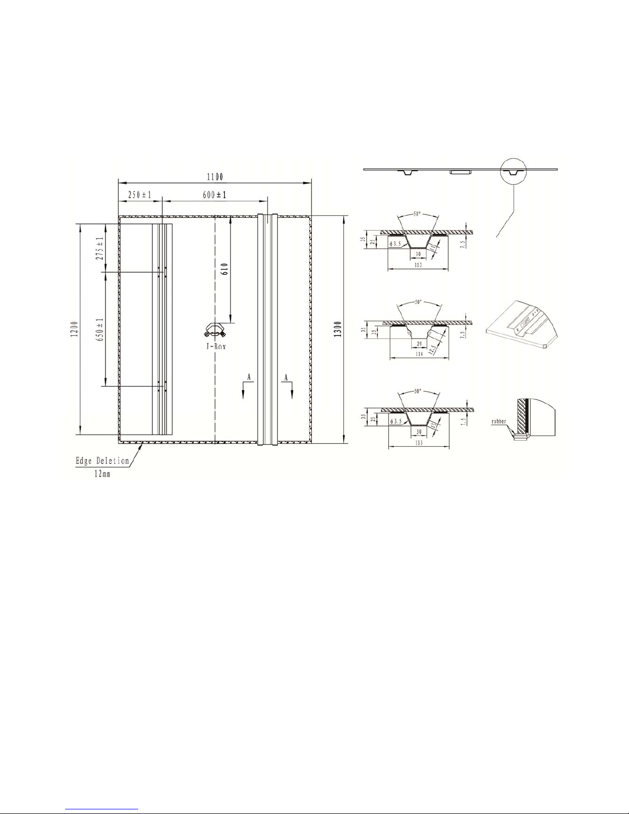
4.6.1. PV modules are to be mounted in a minimum of two different locations per rail, as
shown in the diagrams below.
4.6.2. The mounting structure must be capable of supporti ng the weight of the PV modules and
snow loading (if applicable to the site). It should also be able to withstand seismic
loading in the corresponding applicable seismic areas.
These modules have been evaluat e d b y Underwriters Laboratories Inc for a maximum
positive or negative design loading of 33 lbs/ft
2
.
4.6.3. Key Dimensions
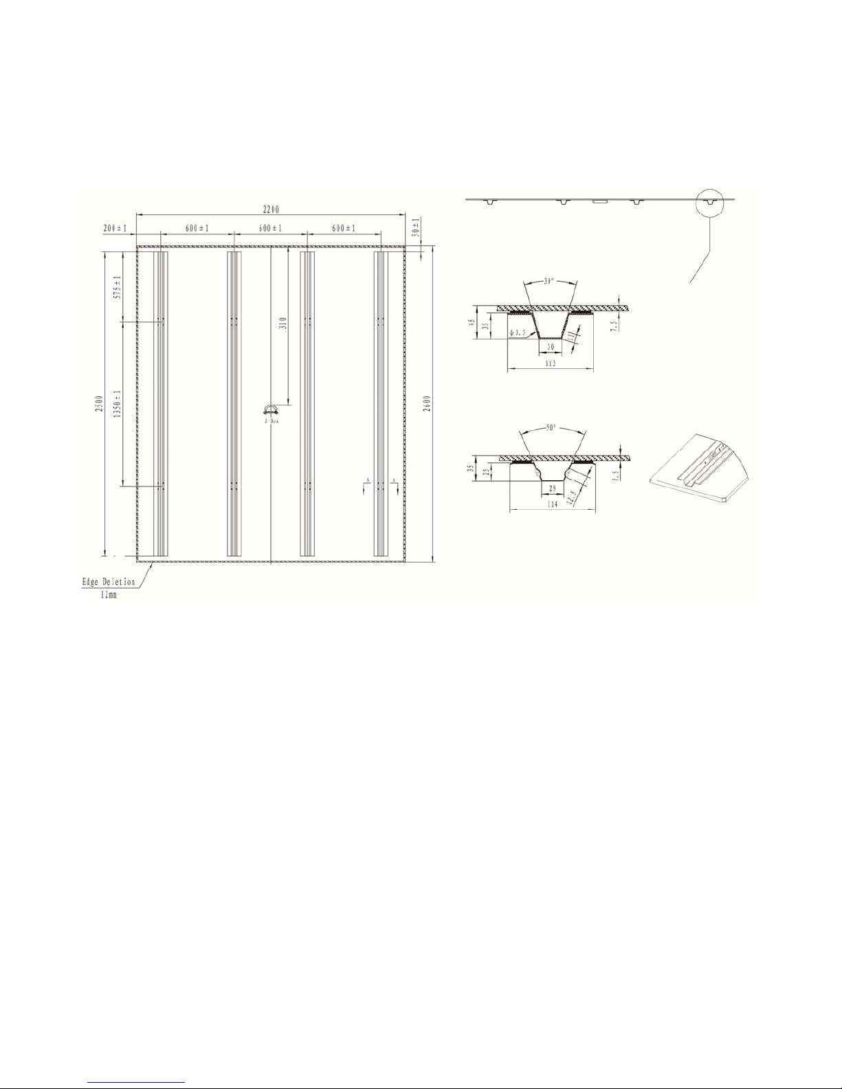
4.6.3.1. The key dimensions are shown in Figure 1, and Figure 2 for a structural
engineer to design an infrastructure. Note all dimensions are in millimeter
unless otherwise specified.
Page 5
河北省廊坊市经济技术开发区华祥路 106 邮编:065001
No.106 Huaxiang Road, E&T Development Zone,Langfang 065001 P.R.China
Figure 1 – 1.3 X 1.1 m Module
Boned rail s
y
stems
Back View#
#Shadow areas are schematic drawing of boned rail system.
ENN Solar Energy provides various boned rail systems upon customs’ request.
1#
2#
3#
1#
2#
3#
Side View
Page 6
河北省廊坊市经济技术开发区华祥路 106 邮编:065001
No.106 Huaxiang Road, E&T Development Zone,Langfang 065001 P.R.China
Figure 2 – 2.6 X 2.2 m Module
4.6.4. Mounting Position
4.6.4.1. The Bracket is mounted to the rail with #10 sheet metal screws as shown in
Figures 1-2 The bracket has a U-shape design to hold a structure with a width
of 50.8mm. The structure holes (d ia meter 10mm) are designed for two bo lts;
size M8 x 1.25 x 65mm, to fasten the brackets to a structure.
4.6.4.2. The modules have been evaluated by UL for mounting using the brackets
provided at the mounting locations in the rails.
Side ViewBack View #
#Shadow areas are schematic drawing of boned rail system.
ENN Solar Energy provides various boned rail systems upon customs’ request.
Boned rail systems
1#
2#
Page 7

河北省廊坊市经济技术开发区华祥路 106 邮编:065001
No.106 Huaxiang Road, E&T Development Zone,Langfang 065001 P.R.China
4.7. Wiring
4.7.1. Warnings
4.7.1.1. If, during self assembly, parts and tools other than those stated by MC are used
or if the preparation and assembl y instructions described here are disregarded
then neither safety nor compliance with the technical data can be guaranteed
4.7.1.2. For protection against electric shock, PV connectors must be isolated from the
power supply while being assemble d or disassembled.
4.7.1.3. The end product must provide protection from electric shock.
4.7.1.4. The integral output connector should only be used where they will not interrupt
current. Unplugging under l oa d : PV plug connections must not be unpl u gged
while under load. They can be placed in a no load state by switching off the
DC/AC converter or breaking the A C ci rcuit interrupter. Plugging and
unplugging while under voltage is permitted.
4.7.1.5. It is unadvisable to use non-tinned cables of type H07RN-F, since with oxidized
copper wires the contact resistances of the crimp conn ection may exceed the
permitted limits.
4.7.1.6. Disconnected connectors should be protected from dirt and water with sealing
caps.
4.7.1.7. Plugged parts are watertight IP67. They can not be used permanently under
water. Do not lay PV connectors on the roof surface.
4.7.2.
Tools
4.7.2.1. Crimping tool.
4.7.2.2. PV-MS Open-end spanner
4.7.2.3.
PV-PST Test Plug
4.7.3. Connectors without cables
4.7.3.1 Connectors
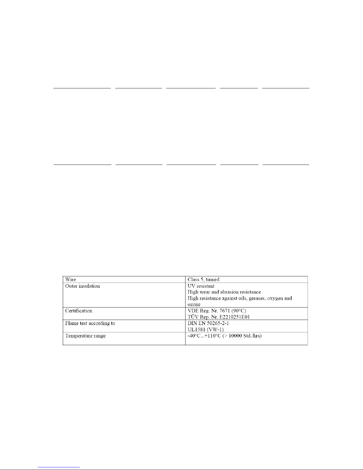
Use only UL recognized connectors which include catalogue numbers PV-KST4
and PV-KBT4 followed by 2.5 or 6, followed by “I” or “II” followed by UR or
additional suffixes. See table below for acceptable cable diam et ers t hat can be use
with each connector.
Page 8
河北省廊坊市经济技术开发区华祥路 106 邮编:065001
No.106 Huaxiang Road, E&T Development Zone,Langfang 065001 P.R.China
Series (TYLZ) Wire types Wire size (AWG)
Number of
strands
Outer Cable
Diameter Range
PV-KST4/2.5I-UR USE or USE-2 8-12 N/A 3.0 – 6.0 mm
PV-KBT4/2.5I-UR USE or USE-2 8-12 N/A 3.0 – 6.0 mm
PV-KST4/2.5II-UR USE or USE-2 8 -12 N/A 5.5 – 9 .0 mm
PV-KBT4/2.5II-UR USE or USE-2 8-12 N/A 5.5 – 9.0 mm
PV-KST4/6I-U R USE or USE-2 8-12 N/A 3.0 – 6.0 mm
PV-KBT4/6I-UR USE or USE-2 8-12 N/A 3.0 – 6.0 mm
PV-KST4/6II-UR USE or USE-2
8-14
N/A 5.5 – 9.0 mm
PV-KBT4/6II-UR USE or USE-2
8-14
N/A 5.5 – 9.0 mm
Series (ZKLA) Wire types Wire size (AWG)
Number of wire
strands (Range)
Outer Cable
Diameter (Range)
PV-KST4/6II-UR PV Wire 12 7 - 52 6.05 - 7.0 mm
PV-KBT4/6II-UR PV Wire 12 7 - 52 6.05 - 7.0 mm
4.7.3.2 Cable Preparation (Reference: Multi-Contact MA231 Assembly Instructions).
4.7.3.2.1. Use appropriate size and type of UL recognized cable for the connector
(14, 12, or 10 AWG with a 90˚C temperature rating, marked sunlight
resistant).
4.7.3.2.2. See table below for additional information important: Cables with class
2, 5 or 6 construction can be connected. It is advantageous to use tinned
conductors. It is unadvisable to use non-tinned cables of type H07RN-F,
since with oxidized copper wires the contact resistances of the crimp
connection may exceed the permitted limits.
4.7.3.2.2 Strip cable insulation. L = 6-7.5 mm. Take care not to cut individual
strands. Recommended tool: Stripping pliers PV-AZM, Order No.
32.6027
4.7.3.3 Crimping
4.7.3.3.1
Crimp the contact onto the wire using the appropriate tool and procedure.
Page 9
河北省廊坊市经济技术开发区华祥路 106 邮编:065001
No.106 Huaxiang Road, E&T Development Zone,Langfang 065001 P.R.China
4.7.3.3.2
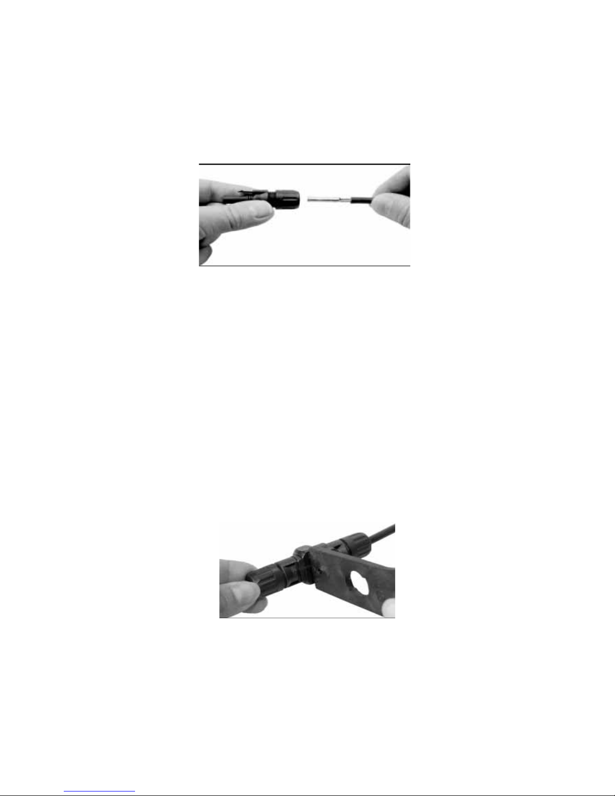
Push the crimped contact into the socket receptacle/plug insulator unt il
it engages. Pull lightly on the lead to check that the metal part has
engaged.
Figure 5 – Contact insertion.
4.7.3.4 Assembly Control
4.7.3.4.1
Insert the test pin with the corresponding side into the socket or plug to
the end position. If the contact is correctly assembled, the white marking
on the test pin must be still visible. (Figure 4)
4.7.3.4.2 Screw on the cable gland, hand-tight, with the tools PV-MS.
4.7.3.4.3 The tightening torque must be adapted to the solar cables used in each
specific case. Typical values lie in a range between 2,5Nm to 3Nm
4.7.4. Plugging
4.7.4.1 Mount the plug connection until it engages. Check correct engagement by
pulling on the coupling.
4.7.5. Unplugging
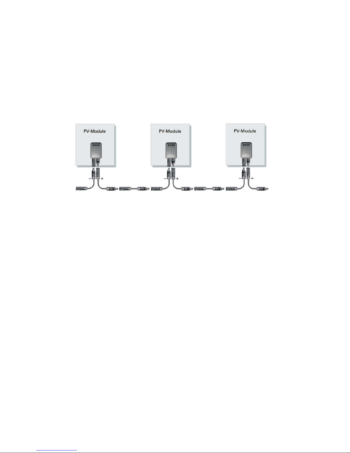
4.7.5.1. The plug connection can only be unlocked with the tool PV-MS (Figure 5)
Figure 6 – Unplugging using PV-MS tool.
4.7.6. Array Wiring
4.7.6.1. Series
Page 10
河北省廊坊市经济技术开发区华祥路 106 邮编:065001
No.106 Huaxiang Road, E&T Development Zone,Langfang 065001 P.R.China
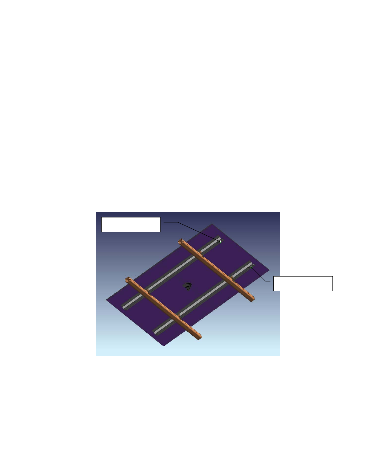
To wire modules in series use an interconnect cable assemblies that has a female
connector on one end and a male connector on the other. The modules can be
connected together in a chain forming a series connected circuit. (See Figure 7).
The maximum current of fuse for the connected circuit can be found in the
section 7.
Figure 7 – Series connection
4.7.6.2. Parallel
To wire the modules in parallel it is necessary to connect the module leads using
a method that meets national and local electrical codes and to us UL listed
hardware
Each module (or series string of modules so connected) shall b e provided with
the maximum series fuse as specified in Section 7.
Page 11
河北省廊坊市经济技术开发区华祥路 106 邮编:065001
No.106 Huaxiang Road, E&T Development Zone,Langfang 065001 P.R.China
4.7.7. Grounding
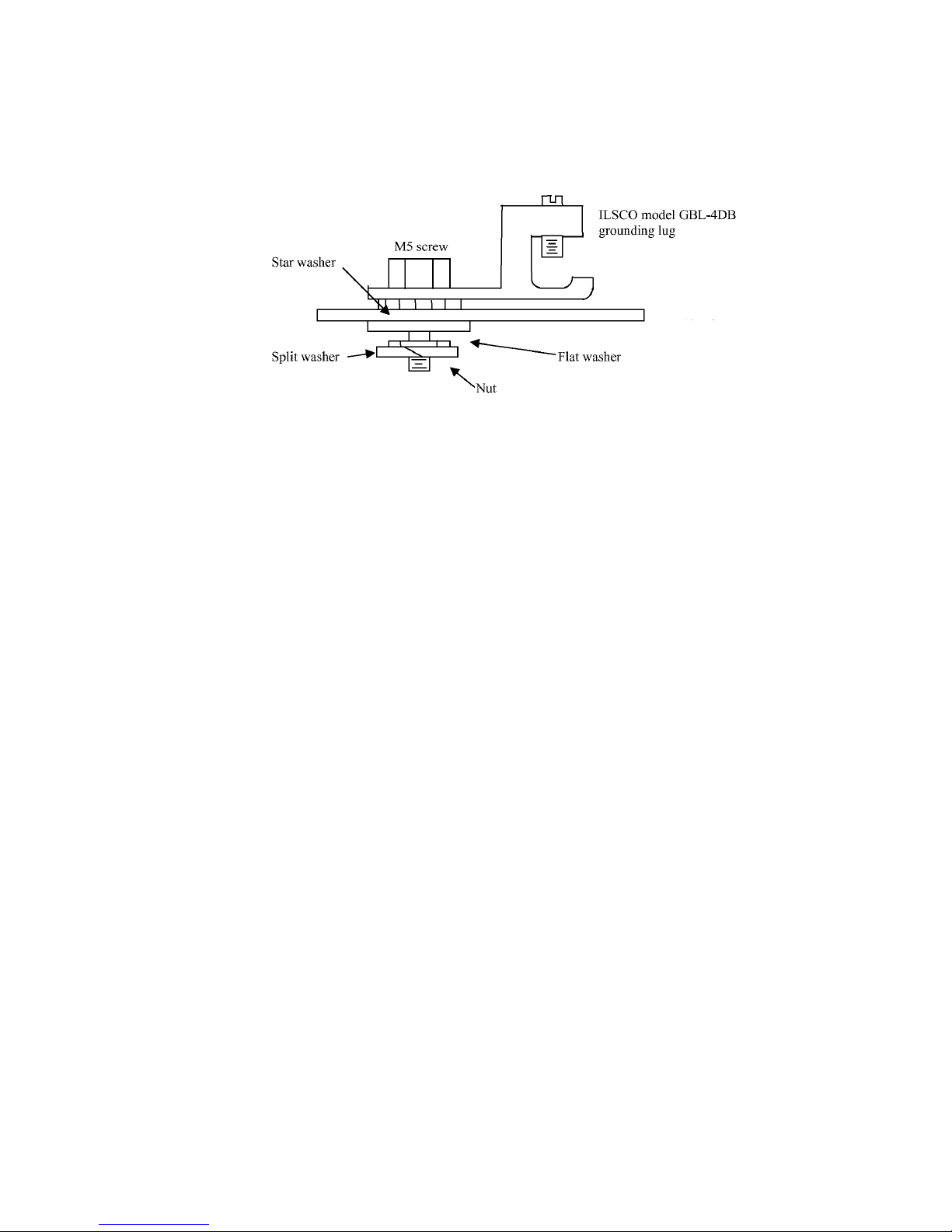
Attach a ground conductor to two grounding bushing lug mounted at the designated location
shown in Figure 8 (An Ilsco GBL-4DB is shown in the Figure). Use an Ilsco GBL-4DB
(Tin Plated) , and M5 stainless steel hardware (screw, lock washer, star washer, flat washer
and nut) as shown in Figure 9. The assembly must be torque to 6.1 Nm . The copper
conductor must be attached to the ground lug using the stainless steel set screw provided by
the lug manufacturer. The electrical wiring of the ground circuit should be such that the
negative leg of the array circuit shall have the same voltage as earth ground, and when
performing a DC voltage measurement between the positive leg of array circuit and earth
ground the meter shall read a positive DC voltage, or when performing a DC voltage
measurement between t he negative leg of array circuit and earth ground the meter shall read
zero volts DC voltage. Please refer to NEC Article 690 on grounding PV arrays for specific
requirements.
Figure 8 – Ground Bushing Lug Locations
Ground Bushing Lug
Ground Bushing Lug
Page 12
河北省廊坊市经济技术开发区华祥路 106 邮编:065001
No.106 Huaxiang Road, E&T Development Zone,Langfang 065001 P.R.China
Figure 9 – Ground Bushing Lug Installation
5. REFERENCES
5.1. Acronyms/Definitions
PV – Photovoltaic
TF – Thin Film
5.2. Documents
Not Applicable
6. METHODS
Not Applicable
Page 13
河北省廊坊市经济技术开发区华祥路 106 邮编:065001
No.106 Huaxiang Road, E&T Development Zone,Langfang 065001 P.R.China
7. ELECTRICAL RATINGS
Stabilized ratings (Displayed on label):
Model
Open
Circuit
Voltage
at STC,
(V dc)+
Rated
Voltage
at STC,
(V dc)+
Maximum
System
Voltage,
(V dc)+
Rated
Current
at STC,
(A dc)+
Short
Circuit
Current
at STC,
(A dc)+
Rated
Maximum
Power at
STC,
(Watts)+
Maximum
Series
Fuse,
(A)
EST-110
1.3 X 1.1 m
139 100
UL 600
IEC 1000
1.10 1.40 110 3
EST-115
1.3 X 1.1 m
140 103
UL 600
IEC 1000
1.12 1.41 115 3
EST-120
1.3 X 1.1 m
141 105
UL 600
IEC 1000
1.14 1.42 120 3
EST-125
1.3 X 1.1 m
142 108
UL 600
IEC 1000
1.16 1.43 125 3
EST-130
1.3 X 1.1 m
143 111
UL 600
IEC 1000
1.18 1.44 130 3
EST-135
1.3 X 1.1 m
146 113
UL 600
IEC 1000
1.20 1.46 135 3
EST-440
2.6 X 2.2 m
280 200
UL 600
IEC 1000
2.20 2.80 440 5
EST-460
2.6 X 2.2 m
282 206
UL 600
IEC 1000
2.24 2.82 460 5
EST-480
2.6 X 2.2 m
284 210
UL 600
IEC 1000
2.28 2.84 480 5
EST-500
2.6 X 2.2 m
286 216
UL 600
IEC 1000
2.32 2.86 500 5
EST-520
2.6 X 2.2 m
288 222
UL 600
IEC 1000
2.36 2.88 520 5
EST-540
2.6 X 2.2 m
292 226
UL 600
IEC 1000
2.39 2.92 540 5
Note: A. During initial 6 weeks of operation,the module has higher electrical output tha n the rated output . The
Pmax may be higher by 15% and the Impp may be higher by 10%.
B. The electrical ratings recorded in the Electrical Rating Label are stabilized values.
Page 14

河北省廊坊市经济技术开发区华祥路 106 邮编:065001
No.106 Huaxiang Road, E&T Development Zone,Langfang 065001 P.R.China
8. ATTACHMENTS
Not Applicable
Page 15

河北省廊坊市经济技术开发区华祥路 106 邮编:065001
No.106 Huaxiang Road, E&T Development Zone,Langfang 065001 P.R.China
THIS PAGE INTENTIONALLY LEFT BLANK.
 Loading...