

Page 1

eM870M Insulation Multimeter
User Manual
Page 2

ennoLogic eM870M Insulation Multimeter
Made in China
User Manual Version 1.1. Revised 1/5/2018.
© 2018 ennoLogic®. All rights reserved.
https://ennologic.com
Page 3

ennoLogic eM870M Insulation Multimeter
Table of Contents
Table of Contents
1. Precautionary Safety Measures........................................................................................................................1
1.1 Important Note: Limited Liability ............................................................................................................................... 1
1.2 Meter Safety Standards ............................................................................................................................................... 1
1.3 Warnings ..................................................................................................................................................................... 2
2. Instrument Description .....................................................................................................................................4
2.1 Features Overview ...................................................................................................................................................... 4
2.2 Main User Elements .................................................................................................................................................... 5
2.3 LCD Display ............................................................................................................................................................. 10
3. Function Descriptions .....................................................................................................................................13
3.1 General Functions ..................................................................................................................................................... 13
3.1.1 TRUE RMS Measurement ................................................................................................................................................ 13
3.1.2 Manual ranging and auto range mode ............................................................................................................................... 13
3.1.3 Maximum, Minimum and Average Value Measurements ................................................................................................. 14
3.1.4 Automatic Shutdown ......................................................................................................................................................... 15
Page 4

ennoLogic eM870M Insulation Multimeter
Table of Contents
3.1.5 Low Battery Voltage Detection ......................................................................................................................................... 15
3.1.6 Backlight ........................................................................................................................................................................... 15
3.1.7 Data Hold .......................................................................................................................................................................... 15
3.2 Measurement Functions ............................................................................................................................................ 16
3.2.1 AC Voltage Measurement ................................................................................................................................................. 16
3.2.2 DC Voltage Measurement ................................................................................................................................................. 18
3.2.3 DC mV/AC mV Measurement .......................................................................................................................................... 20
3.2.4 Frequency & Duty Cycle of Digital Signals and Temperature Measurements .................................................................. 22
3.2.5 Diode and Continuity Tests ............................................................................................................................................... 24
3.2.6 Resistance Measurement ................................................................................................................................................... 26
3.2.7 Capacitance Measurement ................................................................................................................................................. 28
3.2.8 DC and AC μA Current Measurement .............................................................................................................................. 30
3.2.9 DC and AC mA Current Measurement ............................................................................................................................. 32
3.2.10 Insulation Resistance Measurement ................................................................................................................................ 34
3.2.11 Frequency Measurement of Sinusoidal Signals ............................................................................................................... 36
Page 5

ennoLogic eM870M Insulation Multimeter
Table of Contents
4. Technical Specifications ..................................................................................................................................37
4.1 General Specifications .............................................................................................................................................. 37
4.2 Measurement Specifications ..................................................................................................................................... 38
4.2.1 AC Voltage ........................................................................................................................................................................ 38
4.2.2 DC Voltage ........................................................................................................................................................................ 38
4.2.3 AC Current ........................................................................................................................................................................ 39
4.2.4 DC Current ........................................................................................................................................................................ 39
4.2.5 Resistance .......................................................................................................................................................................... 39
4.2.6 Capacitance ....................................................................................................................................................................... 40
4.2.7 Diode ................................................................................................................................................................................. 40
4.2.8 Frequency of Square Waveforms ...................................................................................................................................... 40
4.2.9 Temperature....................................................................................................................................................................... 40
4.2.10 Frequency of Sinusoidal Signals ..................................................................................................................................... 40
4.2.11 Duty Cycle ....................................................................................................................................................................... 41
4.2.12 Insulation Resistance ....................................................................................................................................................... 41
Page 6

ennoLogic eM870M Insulation Multimeter
Table of Contents
5. Maintenance .....................................................................................................................................................42
5.1 General Maintenance ................................................................................................................................................ 42
5.1 Battery Replacement ................................................................................................................................................. 42
5.2 Fuse Replacement ..................................................................................................................................................... 43
6. Accessories........................................................................................................................................................44
Page 7

ennoLogic eM870M Insulation Multimeter
Precautionary Safety Measures
1
1. Precautionary Safety Measures
1.1 Important Note: Limited Liability
Cascadia Innovations is the exclusive distributor of all ennoLogic® products. Except as explicitly stated, Cascadia
Innovations is not liable for direct, indirect, incidental, or other types of damages arising out of, or resulting from the
use of this product. By using the eM870M you agree to hold ennoLogic® and Cascadia Innovations harmless for any
and all consequences of the use of this product or application of data from the use of this instrument.
1.2 Meter Safety Standards
The insulation multimeter eM870M was designed and manufactured according to the safety requirements specified in
the IEC61010-1 standard for electronic test instruments and hand-held digital multimeters. Its design and
manufacturing comply with Measurement Category 1000V CAT III of IEC 61010-1 and Pollution Degree 2.
The meter conforms to the following European Union directives: 89/336/EEC (Electromagnetic Compatibility EMC),
73/23/EEC (Low Voltage Directive LVD) and 93/68/EEC (CE Mark).
Page 8

ennoLogic eM870M Insulation Multimeter
Precautionary Safety Measures
2
1.3 Warnings
Before first use of the meter please check if the housing shows any cracks or if any plastic parts are missing, and
check whether the test leads are damaged or have any exposed metal. The meter must be used only if there are no
problems or damage affecting insulation.
Please read the operating instructions and safety measures sections in this manual carefully. Using the meter
outside the methods specified in this manual may cause damage to the meter or other equipment.
Do not use the meter or test leads if they appear to be damaged.
Do not operate the meter around explosive gas, steam, vapor or dust.
Caution when working with voltages above 60V DC or 30V AC rms, there is the possibility of a shock hazard.
Avoid direct body contact with ground during measurement, or with any metal object that may be at ground
potential. The body should be kept insulated from ground with dry insulating shoes, insulating pads or insulating
clothes.
When performing measurements with a test probe make sure you grab the probe behind the protective plastic ridge
designed to protect your fingers from making accidental contact with the probe tip or circuit.
Page 9

ennoLogic eM870M Insulation Multimeter
Precautionary Safety Measures
3
Do not attempt to measure voltages above 1000V AC or 1000V DC, the meter may get damaged and/or the
operator’s safety may be threatened if the maximum limit for voltage measurements is exceeded.
To avoid false readings, which could lead to possible electric shock or personal injury, replace the battery as soon
as the battery indicator appears.
Before installing or replacing the battery, disconnect test leads and/or any connectors from any circuit under test,
turn the meter off and remove test leads from the input terminals.
Use AAA batteries and make sure to insert them with the proper polarity.
When measuring voltage or current be certain that the test leads are connected to the correct input terminals.
Any adjustments, maintenance or repair work on the meter should only be performed by qualified personnel.
If any faults or abnormalities are observed, take the instrument out of service and ensure that it cannot be used
until it has been checked out.
If the meter is not going to be used for an extended period of time, take out the batteries and do not store the meter
in high temperature or high humidity environments.
Page 10

ennoLogic eM870M Insulation Multimeter
Instrument Description
4
2. Instrument Description
2.1 Features Overview
5000 counts digital display
AC Voltage and DC Voltage measurements up to 1000V
DC measurement accuracy as low as 0.1%
High resolution: resistance 0.1Ω, voltage 10µV
Digital frequency and sinusoidal frequency measurement, as well as duty cycle
Capacitance measurements, range 0.1nF to 1000µF
AC True RMS measurements
Maximum and minimum values
Insulation resistance measurement, range: 50KΩ to 2GΩ
Automatic shutdown or continuous-ON mode
Backlight
Overload protection
Secondary plastic shell with insulating performance of 1000V CAT III
Page 11

ennoLogic eM870M Insulation Multimeter
Instrument Description
5
2.2 Main User Elements
The front panel is shown in Figure 2-1,
and its user elements are described below:
Figure 2-1
1
15
234
5
6
12
11
7
8
9
10
14
13
uA
mA
V
mV
Hz
Insulation+DMM
V
INS
50V
1000V
Insulation
ON/OFF
INS
mA uA
COM
V
Hz
CAT II 1000V
CAT III 600V
500mA MAX
INSULATION
MAX/MIN
LIGHT
Hz/Duty
BEEP
RANGE
HOLD
Page 12

ennoLogic eM870M Insulation Multimeter
Instrument Description
6
(1)
V
Hz
Terminal
Connection terminal for the red (positive) test lead for all measurement functions except for current measurement and insulation
resistance measurement. Hereinafter referred to as V terminal.
(2) COM Terminal
Connection terminal for the black (common reference) test lead for all measurements except for insulation resistance
measurement.
(3) mA/µA Terminal
Connection terminal for the red (positive) test lead during mA or µA current measurements. It is also the connection terminal
for the black test lead for insulation resistance measurements.
(4) INS Terminal
Connection terminal for the red test lead during insulation resistance measurements.
(5) Rotary Switch
Used for selecting measurement functions including AC voltage, DC voltage, millivolt, frequency/temperature,
diode/continuity, resistance, capacitance, microamp current, milliamp current, and insulation resistance.
Page 13

ennoLogic eM870M Insulation Multimeter
Instrument Description
7
(6) POWER Switch
Press this switch to turn the meter on and off.
(7) SELECT Key
When the rotary switch is set to position mV, µA, or mA, press the SELECT key to select either DC or AC mode.
When the rotary switch is set to position Hz / Temperature, press the SELECT key to select either frequency / duty cycle
mode or temperature mode.
When the rotary switch is set to position Diode / Continuity, press the SELECT key to select either diode or continuity
mode.
For all other measurement functions, pressing this key has no effect.
To disable the auto power off feature, press and hold the SELECT key while turning the on with the Power switch.
(8) MAX/MIN Key
This key is for measuring maximum, minimum and average values.
1. Press once to enter MAX/MIN/AVG mode.
2. Press again, and the LCD will display the Minimum Value.
3. Press a third time and the LCD will display the Maximum Value.
Page 14

ennoLogic eM870M Insulation Multimeter
Instrument Description
8
4. Press a fourth time and the LCD will display the Average Value.
5. To return to normal measurement mode, press and hold this button for two seconds.
(9) Hz/Duty Key
When the rotary switch is set to position Hz / Temperature, pressing the HZ/DUTY key will switch between frequency and
duty cycle measurement mode.
When any of the AC voltage or AC current measurement functions are selected, pressing the Hz/DUTY key will turn on
the frequency measurement mode. In this mode, the meter will measure and display the frequency of the signal instead of
its voltage or current. Press this key again to exit frequency measurement mode.
(10) LIGHT key
Pressing this key briefly will turn on the backlight of the LCD display, and pressing it again will turn it off. The backlight will
also turn off automatically after ten seconds.
(11) TEST key
During insulation resistance measurement, press the TEST key to start measuring, and press it again to stop measuring.
(12) RANGE key
When the temperature measurement function is selected, press the RANGE key to select Celsius or Fahrenheit.
Page 15

ennoLogic eM870M Insulation Multimeter
Instrument Description
9
For V~, V , mV, , , A and mA measurements, the RANGE key is used to manually select ranges:
1. Press RANGE to enter the manual ranging mode.
2. Press RANGE to step through the ranges available for the selected function.
3. Press and hold RANGE for 2 seconds to return to auto-ranging.
When measuring digital frequencies or testing diodes, pressing the RANGE key will have no effect.
When performing insulation resistance measurement, use the RANGE key to manually select a test voltage range. There is
no auto-range mode available when measuring insulation resistance.
(13) BEEP Key
When measuring continuity, press the BEEP key to select whether the meter beeps or not when a short is detected.
(14) HOLD Key
Pressing the HOLD key causes the meter to stop updating the display and freezes the current reading. Pressing it again will
resume normal measurement mode.
(15) LCD Display
Displays the measurement readings and various modes (described in detail in the following section.)
Page 16
ennoLogic eM870M Insulation Multimeter
Instrument Description
10
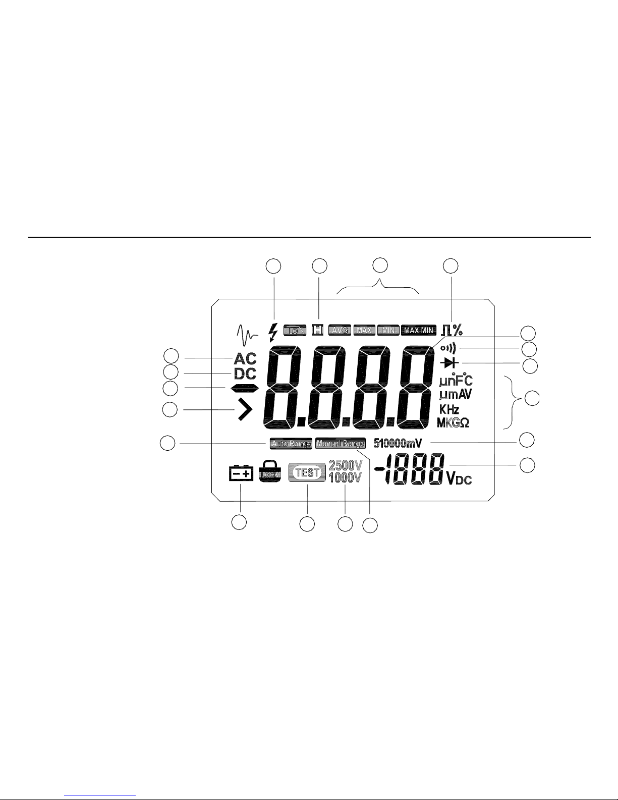
2.3 LCD Display
Figure 2—2
1
17
5
46
7
8
9
10
12
3
13
1415
16
11
18
19
2
Page 17

ennoLogic eM870M Insulation Multimeter
Instrument Description
11
The LCD screen is shown in Figure 2-2 above, and the meanings of the symbols are explained in Table 1 below:
Number of Order
Symbol
Functions
1
µn°F°C
Indicates the measurement unit being either °F or °C for temperature, or µF
or nF for capacitance
µmAV
Indicates the measurement unit being either µA or mA for current, or µV and
mV for voltage
KHz
Indicates the measurement unit being either kHz or Hz for frequency
MKGΩ
Indicates the measurement unit being MΩ, kΩ, GΩ or Ω for resistance
2
The meter is in Diode Test mode.
3
The meter is in Continuity Test mode.
4
The meter is measuring duty cycle.
5
AVG
MAX
MIN
MAX MIN
The display shows the average value (AVG), maximum value (MAX),
minimum value (MIN) or current value (MAX MIN) while in
MAX/MIN/AVG mode.
6
The meter is in Data Hold mode.
7
Warning – High Voltage!
8
AC
Indicator for AC voltage or current
9
DC
Indicator for DC voltage or current
Page 18

ennoLogic eM870M Insulation Multimeter
Instrument Description
12
Table 1 (continued)
10
Indicates negative readings
11
Indicates overload condition when measuring insulation resistance
12
AUTO RANGE
The meter is in Auto range mode in which the meter automatically
selects the range with the best resolution.
13
MANUAL RANGE
The meter is in Manual Range mode in which the user manually
selects the appropriate measurement range.
14
2500V
1000V
Indicates the applied test voltage when performing insulation
resistance measurements (either 50V, 100V, 250V, 500V, or 1000V)
15
TEST
Indicates that an insulation resistance test is now being performed.
16
Low battery indicator
17
Measurement value display area
18
51000
Range indicator when selecting ranges manually such as 5, 50, 500,
1000, 5000, etc.
19
-1888VDC
Real-time display of the applied test voltage when performing
insulation resistance measurements
Page 19

ennoLogic eM870M Insulation Multimeter
Function Descriptions
13
3. Function Descriptions
3.1 General Functions
3.1.1 TRUE RMS Measurement
All AC measurement values are true RMS (true root-mean-square) values. This distinguishes this meter from other meters that
only measure average AC values.
3.1.2 Manual ranging and auto range mode
The Meter has both manual ranging and auto range options. It defaults to auto range mode when turned on.
• In auto range mode, the meter selects the best range for the input detected. This allows you to switch test points
without having to reset the range.
• In manual ranging mode, you override auto range and lock the meter into a specific range.
• The meter defaults to auto range mode in measurement functions that have more than one range. When the meter is in
auto range mode, the symbol “AUTO RANGE” is displayed.
• When the LCD display shows “OL”, it indicates that the measured value exceeds the meter’s maximum range.
Page 20

ennoLogic eM870M Insulation Multimeter
Function Descriptions
14
To enter and exit manual ranging mode:
1. Press the RANGE key. The meter enters manual ranging mode. The LCD symbol “AUTO RANGE” changes to
“MANUAL RANGE”. Each press of the RANGE key increments the range, and the display shows the maximum value
for the selected range next to the symbol “MANUAL RANGE”. When the highest range is reached, the Meter wraps
back to the lowest range.
2. To exit manual ranging mode, press and hold down the RANGE key for two seconds. The Meter returns to the auto
range mode and “AUTO RANGE” is displayed.
3.1.3 Maximum, Minimum and Average Value Measurements
Press the MAX/MIN key to enter the maximum/minimum/average value mode. The meter will continuously track and update
the maximum, minimum, or average values based on which of the three modes is selected.
After entering this mode, the instantaneous value continues to be displayed. Press the MAX/MIN key again, and the LCD will
display the Minimum Value since this mode was entered. Press it a third time and the LCD will display the Maximum Value.
Press it a fourth time and the LCD will display the Average Value. Press it one more time to return to displaying the
instantaneous value. Press and hold the MAX/MIN key for two seconds and the meter will return to the normal measurement
mode. After exiting the MAX/MIN/AVG value mode the recorded maximum, minimum and average values will disappear.
Page 21

ennoLogic eM870M Insulation Multimeter
Function Descriptions
15
3.1.4 Automatic Shutdown
The Meter enters "Sleep mode" and blanks the display if the Meter is on but not used for 15 minutes. The meter will not
automatically shut down while in insulation resistance measurement mode. If you want the meter to operate continuously
without automatically turning off, press and hold the SELECT key when pressing the POWER switch to turn the unit on.
NOTE: The meter will still consume a small amount of energy after its automatic shutdown, so it is recommended to
turn off the POWER switch if the meter remains idle for a long time, otherwise it will drain the batteries.
3.1.5 Low Battery Voltage Detection
When the meter detects that its battery voltage drops below 6.8V, the LCD will display the symbol to indicate that the
AAA batteries of the meter should be replaced.
3.1.6 Backlight
Press the LIGHT key to turn on the backlight of the LCD display. After ten seconds the backlight will automatically turn off. It
is also possible to turn it off before that time by pressing the LIGHT key again. With the backlight on, the meter’s power
consumption will be three times higher. Using the backlight sparingly will extend battery life.
3.1.7 Data Hold
Press the HOLD key to freeze the currently displayed measurement value. Press it again to resume normal measurement mode.
Page 22

ennoLogic eM870M Insulation Multimeter
Function Descriptions
16
3.2 Measurement Functions
3.2.1 AC Voltage Measurement
To measure AC voltages, set up the meter as shown in Figure 3-1:
1. Turn on the power switch and set the rotary switch to position .
2. Connect the red and black test leads to the V and COM terminals respectively.
3. Connect the test leads/probes to the circuit being measured.
4. Read the displayed voltage value. If the meter displays OL, it indicates that the measured voltage exceeds the meter’s range
(1000V in auto range mode) and the test probes should be disconnected from the measured circuit immediately.
5. By pressing the RANGE key, it is possible to select a desired range manually. The display will show what range is
currently active, keep pressing the RANGE key to cycle through the available ranges. If the meter displays OL while in
manual range mode, it is necessary to select a larger range. If OL is displayed with the meter set to its maximum voltage
range, disconnect the test probes from the measured circuit immediately, since the voltage exceeds 1000V (the maximum
AC voltage the meter can measure).
Note: It is normal for the displayed value to be unstable and fluctuate if the test leads are not connected to a circuit.
V
Page 23

ennoLogic eM870M Insulation Multimeter
Function Descriptions
17
AC Voltage Measurement
Warning
Do not attempt to
measure voltages
above 1000V!
uA
mA
V
mV
Hz
Insulation+DMM
V
INS
50V
1000V
Insulation
ON/OFF
INS
mA uA
COM
V
Hz
CAT II 1000V
CAT III 600V
500mA MAX
INSULATION
V
MAX/MIN
LIGHT
Hz/Duty
BEEPRANGE
HOLD
Page 24

ennoLogic eM870M Insulation Multimeter
Function Descriptions
18
3.2.2 DC Voltage Measurement
To measure DC voltages, set up the meter as shown in Figure 3-2:
1. Turn on the power switch and set the rotary-table switch to position .
2. Connect the red and black test leads to the V and COM terminals respectively.
3. Connect the test leads/probes to the circuit being measured.
4. Read the displayed voltage value. The polarity of the red test lead connection will be shown on the LCD display. If the
meter displays OL, it indicates that the measured voltage exceeds the meter’s range (1000V in auto range mode) and the
test probes should be disconnected from the measured circuit immediately.
5. By pressing the RANGE key, it is possible to select a desired range manually. The display will show what range is
currently active, keep pressing the RANGE key to cycle through the available ranges. If the meter displays OL while in
manual range mode, it is necessary to select a larger range. If OL is displayed with the meter set to its maximum voltage
range, disconnect the test probes from the measured circuit immediately, since the voltage exceeds 1000V (the maximum
DC voltage the meter can measure).
Note: It is normal for the displayed value to be unstable and fluctuate if the test leads are not connected to a circuit.
V
Page 25

ennoLogic eM870M Insulation Multimeter
Function Descriptions
19
DC Voltage Measurement
Warning
Do not attempt to
measure voltages
above 1000V!
uA
mA
V
mV
Hz
Insulation+DMM
V
INS
50V
1000V
Insulation
ON/OFF
INS
mA uA
COM
V
Hz
CAT II 1000V
CAT III 600V
500mA MAX
INSULATION
V
MAX/MIN
LIGHT
Hz/Duty
BEEPRANGE
HOLD
Page 26

ennoLogic eM870M Insulation Multimeter
Function Descriptions
20
3.2.3 DC mV/AC mV Measurement
To measure small DC and AC voltages up to 500mV, set up the meter as shown in Figure 3-3:
1. Turn on the power switch and set the rotary switch to position .
2. Connect the red and black test leads to the V and COM terminals respectively.
3. Press the SELECT key to select DC mV or AC mV measurement mode.
4. Connect the test leads/probes to the circuit being measured.
5. Read the displayed voltage value. The polarity of the red test lead connection will be indicated when making a DC Volt
measurement. If the meter displays OL, it indicates that the measured voltage exceeds the meter’s range in this mode and
the test probes should be disconnected from the measured circuit immediately.
6. By pressing the RANGE key, it is possible to select a desired range manually. The display will show what range is
currently active, keep pressing the RANGE key to cycle through the available ranges. If the meter displays OL while in
manual range mode, it is necessary to select a larger range. If OL is displayed with the meter set to its maximum voltage
range, disconnect the test probes from the measured circuit immediately, since the voltage exceeds the maximum voltage
the meter can measure in this mode.
Note: It is normal for the displayed value to be unstable and fluctuate if the test leads are not connected to a circuit.
mV
Page 27

ennoLogic eM870M Insulation Multimeter
Function Descriptions
21
DC mV / AC mV Measurement
Figure 3-3
uA
mA
V
mV
Hz
Insulation+DMM
V
INS
50V
1000V
Insulation
ON/OFF
INS
mA uA
COM
V
Hz
CAT II 1000V
CAT III 600V
500mA MAX
INSULATION
mV
MAX/MIN
LIGHT
Hz/Duty
BEEP
RANGE
HOLD
Page 28

ennoLogic eM870M Insulation Multimeter
Function Descriptions
22
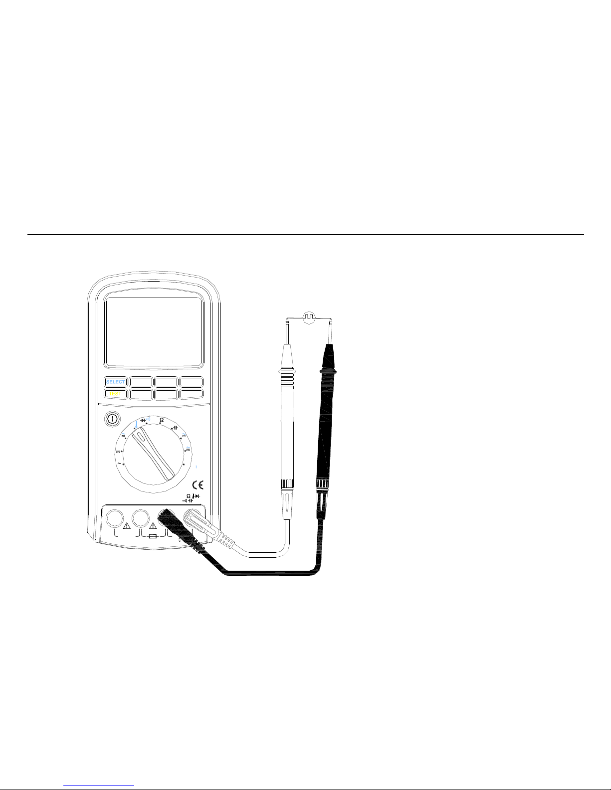
3.2.4 Frequency & Duty Cycle of Digital Signals and Temperature Measurements
To measure the frequency or duty cycle of a digital signal, set up the meter as shown in Figure 3-4. Please note that the peak to
peak voltage of the digital signal must be between 2.5V and 5V, its frequency in the range of 5Hz ~ 2MHz, and its duty cycle
between 5% and 95%. Duty cycle refers to (pulse width of high cycle / total period of rectangular waveform signal) x 100%.
The same rotary switch position and connection terminals are used to measure temperatures with the enclosed thermocouple
probe.
1. Turn on the power switch and set the rotary switch to position .
2. When performing frequency and duty cycle measurements of digital signals, insert the test leads into the VΩHz and COM
terminals respectively. When performing temperature measurements, connect the positive/red plug of the thermocouple to
the V terminal and the negative/black plug to the COM terminal.
3. Press the Hz/Duty key to select frequency (Hz) or duty cycle ( ) measurement mode.
4. For frequency and duty cycle measurements: connect the test leads/probes to the circuit being measured. Read the
displayed value. If the frequency of the measured signal is lower or higher than the meter’s measurement range, the display
will show zero. If the amplitude of the signal is too low or the low level is larger than 1 Volt, the display will also show
zero. Note that the meter will always auto range for frequency and duty cycle measurements. Pressing the RANGE key has
no effect.
5. For temperature measurements: press the SELECT key to select temperature measurement mode. If the meter’s input V
and COM terminals are not connected to a thermocouple, the ‘OPEn’ symbol will be displayed. Connect the positive/red
plug of the thermocouple to the V terminal and the negative/black plug to the COM terminal, and read the displayed
temperature value. Press the RANGE key to select Celsius or Fahrenheit. If the measured temperature is higher than the
meter’s measurement range, it will display the internal temperature of the instrument and the ‘OL’ symbol.
Hz
Page 29
ennoLogic eM870M Insulation Multimeter
Function Descriptions
23
Frequency & Duty Cycle of
Digital Signals and
Temperature Measurements
Figure 3-4
uA
mA
V
mV
Hz
Insulation+DMM
V
INS
50V
1000V
Insulation
ON/OFF
INS
mA uA
COM
V
Hz
CAT II 1000V
CAT III 600V
500mA MAX
INSULATION
MAX/MIN
LIGHT
Hz/Duty
BEEP
RANGE
HOLD
Page 30
ennoLogic eM870M Insulation Multimeter
Function Descriptions
24
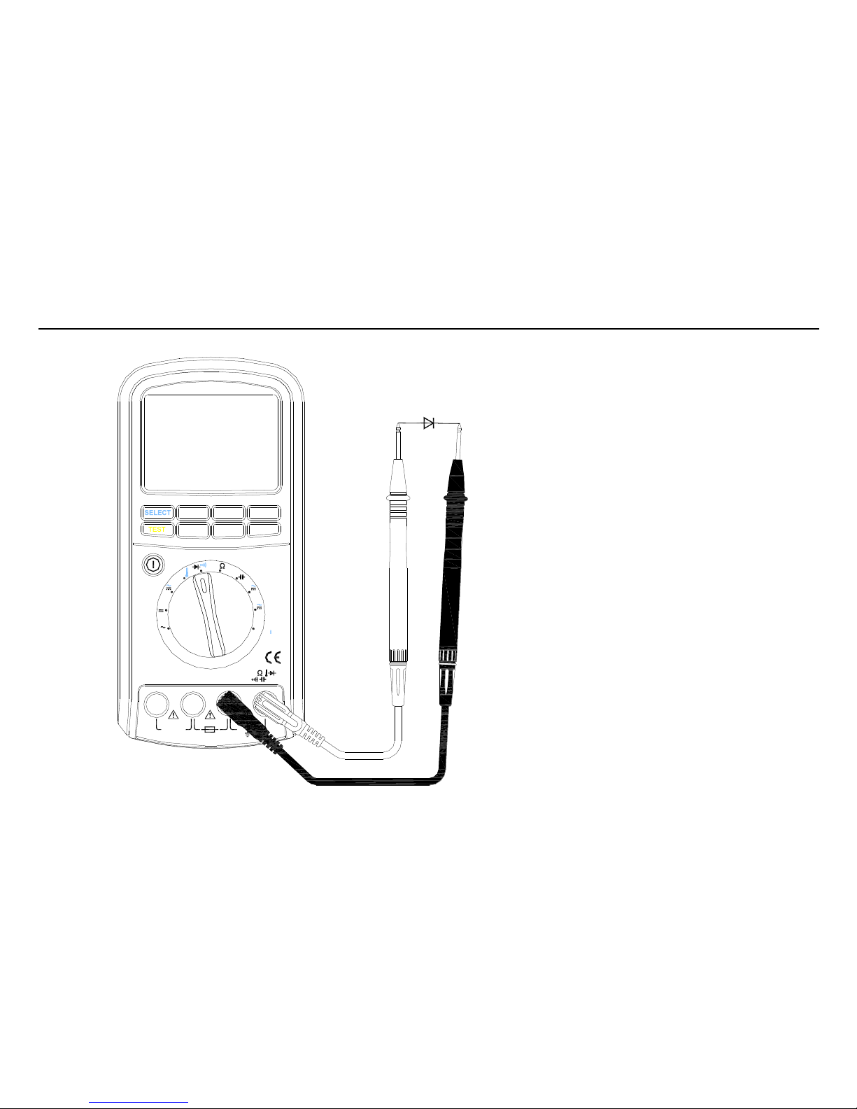
3.2.5 Diode and Continuity Tests
To test a diode outside of a circuit, or test for continuity, set up the meter as shown in Figure 3-5:
1. Turn on the power switch and set the rotary switch to position .
2. Connect the red and black test leads to the V and COM terminals respectively.
3. Press the SELECT key to select diode ( ) or continuity ( ) test mode.
4. For diode tests, connect the red probe to the anode of the diode and the black probe to its cathode. The display will show
the forward voltage drop (range 0 ~ 2.5V). Next, connect the black probe to the anode of the diode and the red probe to its
cathode. “OL” appearing on the display will indicate normal diode function. If the display doesn’t show OL, the diode has
a high reverse leakage current.
5. For continuity tests, a resistance between test leads of less than 25Ω is indicated by continuous beeping, assuming the
beeper was not disabled by pressing the BEEP key. Continuity tests are commonly used to check for opens and shorts of a
circuit.
Note: If you are performing diode or continuity tests on a circuit board, it is necessary to turn off the power to the circuit
board before measuring. A component tested in-circuit may have other components connected to it in parallel, resulting in
different values than if tested outside the circuit or having at least one of its probed leads isolated.
Page 31
ennoLogic eM870M Insulation Multimeter
Function Descriptions
25
Diode and Continuity Tests
Figure 3-5
uA
mA
V
mV
Hz
Insulation+DMM
V
INS
50V
1000V
Insulation
ON/OFF
INS
mA uA
COM
V
Hz
CAT II 1000V
CAT III 600V
500mA MAX
INSULATION
MAX/MIN
LIGHT
Hz/Duty
BEEP
RANGE
HOLD
Page 32

ennoLogic eM870M Insulation Multimeter
Function Descriptions
26
3.2.6 Resistance Measurement
To measure resistance, set up the meter as shown in Figure 3-6:
1. Turn on the power switch and set the rotary switch to position .
2. Connect the red and black test leads to the V and COM terminals respectively.
3. Connect the test leads/probes to the two ends of a resistor and read the displayed resistance value. If the display shows OL,
it indicates that the resistor is larger than 50MΩ (resistance measurement range is 0.1Ω ~ 50MΩ).
4. By pressing the RANGE key, it is possible to select a desired range manually. The display will show what range is
currently active, keep pressing the RANGE key to cycle through the available ranges. If the meter displays OL while in
manual range mode, it is necessary to select a larger range.
Note: If you are performing resistance measurements on a circuit board, it is necessary to turn off the power to the circuit
board before measuring. A resistor tested in-circuit may have other components connected to it in parallel, resulting in
different values than if tested outside the circuit or having at least one of its probed leads isolated. Disconnecting power
will also prevent damage to the meter, or false readings that will occur if the resistor is carrying a current induced by a
source other than the meter itself.
Page 33

ennoLogic eM870M Insulation Multimeter
Function Descriptions
27
Resistance Measurement
Figure 3-6
uA
mA
V
mV
Hz
Insulation+DMM
V
INS
50V
1000V
Insulation
ON/OFF
INS
mA uA
COM
V
Hz
CAT II 1000V
CAT III 600V
500mA MAX
INSULATION
MAX/MIN
LIGHT
Hz/Duty
BEEP
RANGE
HOLD
Page 34

ennoLogic eM870M Insulation Multimeter
Function Descriptions
28
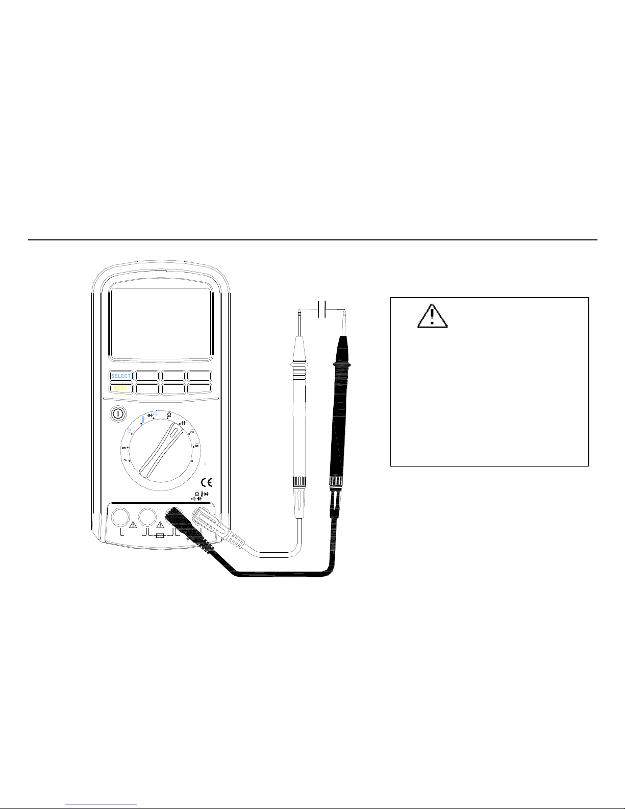
3.2.7 Capacitance Measurement
To measure capacitance, set up the meter as shown in Figure 3-7:
1. Turn on the power switch and set the rotary switch to position .
2. Connect the red and black test leads to the V and COM terminals respectively.
3. To avoid electric shock and/or damage to the instrument, disconnect power and discharge the capacitor to be measured
before measuring capacitance by shorting its two leads briefly. Use the DC voltage function to confirm that the capacitor is
discharged.
4. If the measured capacitor is polarized, make sure to connect the red probe to the positive lead of the capacitor and the black
probe to its negative lead. If the capacitor is not polarized, simply connect the two probes to the capacitor leads.
5. Read the displayed capacitance value. The capacitance measurement range is 0.1nF ~ 1000µF. If the capacitance value
is >1000µF, the meter will display OL, and if it’s < 0.1nF, it will display zero.
6. By pressing the RANGE key, it is possible to select a desired range manually. The display will show what range is
currently active, keep pressing the RANGE key to cycle through the available ranges. If the meter displays OL while in
manual range mode, it is necessary to select a larger range. If the largest range has already been selected, OL means the
measured capacitance value is > 1300µF.
Notes: In order to ensure measurement accuracy when measuring large capacitors between 500μF and 1000μF, the meter
will take a long time to charge/discharge the capacitor under test. The result is a relatively slow refresh rate of the displayed
value.
Do not perform capacitance measurements on components that are part of a circuit board. Other components of the circuit
connected to the component under test may lead to large errors.
Page 35
ennoLogic eM870M Insulation Multimeter
Function Descriptions
29
Capacitance Measurement
uA
mA
V
mV
Hz
Insulation+DMM
V
INS
50V
1000V
Insulation
ON/OFF
INS
mA uA
COM
V
Hz
CAT II 1000V
CAT III 600V
500mA MAX
INSULATION
+
-
MAX/MIN
LIGHT
Hz/Duty
BEEP
RANGE
HOLD
Warning
To avoid electrical shock and/or
damage to the instrument, disconnect
the circuit power and discharge all
high-voltage capacitors before
measuring capacitance. Use the DC
voltage function to confirm that the
capacitor is discharged.
Page 36

ennoLogic eM870M Insulation Multimeter
Function Descriptions
30
3.2.8 DC and AC μA Current Measurement
To measure small DC and AC currents up to 5000µA, set up the meter as shown in Figure 3-8:
1. Turn on the power switch and set the rotary switch to position .
2. Connect the red and black test leads to the mA/µA and COM terminals respectively.
3. Press the SELECT key to select DC μA or AC μA measurement mode.
4. Turn off power to the measured circuit and discharge all high voltage capacitors.
5. Disconnect (break) the circuit path to be tested.
6. Connect or touch the black probe to the negative side of the break and connect or touch the red probe to the positive side of
the break. (Reversing the leads will give a negative reading, but will not damage the meter.)
7. Turn on power to the circuit; then read the display. By pressing the RANGE key, it is possible to select a desired range
manually. The display will show what range is currently active, keep pressing the RANGE key to cycle through the
available ranges. If the meter displays OL while in manual range mode, it is necessary to select a larger range.
8. Turn off power to the circuit and discharge all high voltage capacitors. Remove the meter and restore the circuit to normal
operation.
Page 37

ennoLogic eM870M Insulation Multimeter
Function Descriptions
31
DC µA
AC µA
Measurement
Figure 3-8
uA
mA
V
mV
Hz
Insulation+DMM
V
INS
50V
1000V
Insulation
ON/OFF
INS
mA uA
COM
V
Hz
CAT II 1000V
CAT III 600V
INSULATION
i i
MAX/MIN
LIGHT
Hz/Duty
BEEP
RANGE
HOLD
Page 38

ennoLogic eM870M Insulation Multimeter
Function Descriptions
32
3.2.9 DC and AC mA Current Measurement
To measure DC and AC currents in the mA range of 0.01mA ~ 500mA, set up the meter as shown in Figure 3-9:
1. Turn on the power switch and set the rotary switch to position .
2. Connect the red and black test leads to the mA/µA and COM terminals respectively.
3. Press the SELECT key to select DC mA or AC mA measurement mode.
4. Turn off power to the measured circuit and discharge all high voltage capacitors.
5. Disconnect (break) the circuit path to be tested.
6. Connect or touch the black probe to the negative side of the break and connect or touch the red probe to the positive side of
the break. (Reversing the leads will give a negative reading, but will not damage the meter.)
7. Turn on power to the circuit; then read the display. By pressing the RANGE key, it is possible to select a desired range
manually. The display will show what range is currently active, keep pressing the RANGE key to cycle through the
available ranges. If the meter displays OL while in manual range mode, it is necessary to select a larger range.
8. Turn off power to the circuit and discharge all high voltage capacitors. Remove the meter and restore the circuit to normal
operation.
mA
Page 39

ennoLogic eM870M Insulation Multimeter
Function Descriptions
33
DC mA
AC mA
Measurement
Figure 3-9
uA
mA
V
mV
Hz
Insulation+DMM
V
INS
50V
1000V
Insulation
ON/OFF
INS
mA uA
COM
V
Hz
CAT II 1000V
CAT III 600V
INSULATION
i i
MAX/MIN
LIGHT
Hz/Duty
BEEP
RANGE
HOLD
Page 40
ennoLogic eM870M Insulation Multimeter
Function Descriptions
34
3.2.10 Insulation Resistance Measurement
To measure insulation resistance, set up the meter as shown in Figure 3-10:
1. Turn on the power switch and set the rotary switch to position .
2. Connect the red and black test leads to the INS and mA/µA terminals respectively. (NOT to the COM terminal!)
3. Connect the red probe and the black probe to the two ends of the measured insulator. Press the RANGE key to select a
suitable test voltage range (50V, 100V, 250V, 500V, or 1000V). The measurement range for insulation resistance
corresponds to the available test voltage ranges as follows: 50V---10kΩ~50MΩ, 100V---10kΩ~100MΩ,
250V---100kΩ~250MΩ, 500V---100kΩ~500MΩ, 1000V---100kΩ~2GΩ). Note: There is no auto ranging when
performing insulation resistance measurements.
Warning: After pressing the TEST key, the meter will generate a high voltage of up to 1000V! Do not touch
the leads or probes when the test is active to avoid the risk of shock!
4. Press the TEST key to start measuring. The meter will apply a test voltage to the insulator up to the selected range to
determine the insulation resistance. If the measured insulation resistance is lower than the meter’s measurement range, the
meter will stop measuring automatically. Otherwise the meter will display the result of the test (the insulation resistance).
Press the TEST key again to stop measuring.
Notes: When using this function, the meter generates a high voltage up to 1000V. Please be careful to avoid the risk of
shock. Also note that the automatic shutdown feature is disabled when performing insulation resistance measurements.
INS
Page 41

ennoLogic eM870M Insulation Multimeter
Function Descriptions
35
Insulation Resistance
Measurement
Figure 3-10
uA
mA
V
mV
Hz
Insulation+DMM
V
INS
50V
1000V
Insulation
ON/OFF
INS
mA uA
COM
V
Hz
CAT II 1000V
CAT III 600V
500mA MAX
INSUL
uA/mA
MAX/MIN
LIGHT
Hz/Duty
BEEP
RANGE
HOLD
Warning
When using this function, the
meter generates a high voltage of
up to 1000V! Do not touch the
leads or probes when the test is
active to avoid the risk of shock!
Page 42

ennoLogic eM870M Insulation Multimeter
Function Descriptions
36
3.2.11 Frequency Measurement of Sinusoidal Signals
To measure the frequency of sinusoidal signals, set up the meter as shown in Figures 3-1, 3-3, 3-8 or 3-9. The measurement
range is 5Hz~200KHz:
1. When measuring AC voltages or AC currents, it is possible to measure and display the frequency of the signal by pressing
the Hz/Duty key. However, the signal must meet certain requirements regarding amplitude depending on the selected
measurement range. See Table 3-1 for detailed specifications.
2. If the rotary switch is set to position ACV, after pressing the Hz/Duty key the display will show the meter’s currently
selected voltage range. It is also possible to change the range by pressing the RANGE key.
3. Press the Hz/Duty key again to exit frequency measurement mode.
Table 3-1
Range
Sensitivity Threshold (RMS sine wave)
500mV
100mV
5V
0.4V
50V
4V
500V
40V
1000V
400V
5000µA
1mA
500mA
100mA
Page 43

ennoLogic eM870M Insulation Multimeter
Technical Specifications
37
4. Technical Specifications
4.1 General Specifications
• Maximum voltage between terminals and earth ground: 1000V AC rms or 1000V DC.
• Measurement Category 1000V CAT III of IEC 61010-1 and Pollution Degree 2.
• 5000 counts digital display, automatic and manual range.
• Basic sampling rate 2.5 times per second. 51 segment analog bar.
• When the rotary switch is set to position mV, frequency, diode, resistance or capacitance, the maximum overload protection
voltage will be 250V (effective value). When set to μA or mA, the overload protection current will be 0.64A.
• Over range indication OL.
• Fuse Protection: µA and mA: F 0.63A/600V.
• Power: 6x AAA batteries.
• Low battery voltage indicator, displayed when the total voltage of the 6 AAA batteries is < 6.8V.
• Operating temperature: 0°C ~ 30°C (32°F ~ 86°F): relative humidity 0 ~ 80%; 31°C ~ 51°C (87°F ~ 124°F): relative humidity 0 ~
50%
• Storage temperature: -20°C ~ 60°C (relative humidity <= 80%)
• Altitude: Operation at less than 2000 m, Storage at less than 10,000 m
• Volume: 200 mm x 100 mm x 40 mm (7.90” x 3.9” x 1.6”)
• Weight: 560g (1.23lbs.)
Page 44

ennoLogic eM870M Insulation Multimeter
Technical Specifications
38
4.2 Measurement Specifications
The accuracies listed below are guaranteed within one year of use under normal operating conditions at temperatures between
18°C and 28°C (64°F and 82°F) and a relative humidity of less than 80%. The accuracy is stated as: ± (xx % of reading + x
number of lower digits).
4.2.1 AC Voltage
Notes: above accuracies can be guaranteed within 10% ~ 100% of the full range.
4.2.2 DC Voltage
Range
Resolution
Accuracy
500mV
0. 1mV
±(0.1% +2)
5V
1mV
±(0.1% +2)
50V
10mV
±(0.1% +2)
500V
0.1V
±(0.1% +2)
1000V
1V
±(0.1% +2)
Notes: above accuracies can be guaranteed over the full range
Range
Resolution
Accuracy
40Hz~400Hz
500mV
0.1mV
±(0.8% +4)
5V
1mV
±(0.8% +4)
50V
10mV
±(0.8% +4)
500V
0.1V
±(0.8% +4)
1000V
1V
±(1.0% +4)
Page 45

ennoLogic eM870M Insulation Multimeter
Technical Specifications
39
4.2.3 AC Current
Range
Resolution
Accuracy
Voltage Drop
40Hz~400Hz
500μA
0.1μA
±(0.8% +4)
102µV/µA
5000μA
1μA
±(0.8% +4)
50mA
10μA
±(0.8% +4)
1.5mV/mA
500mA
0.1mA
±(0.8% +4)
Notes: above accuracies can be guaranteed within 10% ~ 100% of the full range
4.2.4 DC Current
Range
Resolution
Accuracy
Voltage Drop
500μA
0. 1μA
±(0.2% +2)
102µV/µA
5000μA
1μA
±(0.2% +2)
50mA
10μA
±(0.2% +2)
1.5mV/mA
500mA
0.1mA
±(0.2% +2)
Notes: above accuracies can be guaranteed over the full range
4.2.5 Resistance
Range
Resolution
Accuracy
500Ω
0.1Ω
±(0.3% +5)
5KΩ
1Ω
±(0.3% +5)
50KΩ
10Ω
±(0.3% +5)
500KΩ
100Ω
±(0.3% +5)
5MΩ
1KΩ
±(0.3% +5)
50MΩ
10KΩ
±(0.8% +5)
Notes: above accuracies can be guaranteed over the full range
Page 46

ennoLogic eM870M Insulation Multimeter
Technical Specifications
40
4.2.6 Capacitance
Range
Resolution
Accuracy
50nF
0.01nF
±(2.5% +10)
500nF
0.1nF
±(2.5% +10)
5μF
1nF
±(2% +10)
50μF
10nF
±(2% +10)
500μF
0.1μF
±(2% +10)
1000μF
1μF
±(3% +10)
Notes: above accuracies can be guaranteed over the full range for film capacitors or capacitors of better quality
4.2.7 Diode
Range
Resolution
Accuracy
2.5V
1mV
±(1%+5)
Notes: the test current is approximately 0.7mA
4.2.8 Frequency of Square Waveforms
Frequency Range
Sensitivity
Resolution
Accuracy
5Hz∽2MHz
Vp 2∽5V square wave
0.001Hz
±4counts
4.2.9 Temperature
Frequency Range
Resolution
Accuracy
-40℃~537℃
0.1℃
±(1% +1.5℃)
4.2.10 Frequency of Sinusoidal Signals
Frequency Range
Voltage/Current Range
Sensitivity
Resolution
Accuracy
5Hz∽200KHz
(sine wave)
500mV
200mV
0.001Hz
±4 counts
5V
0.5V
Page 47
ennoLogic eM870M Insulation Multimeter
Technical Specifications
41
50V
4V
500V
40V
1000V
400V
5000μA
1mA
500mA
100mA
Notes: The accuracy will be reduced for signals with low voltage or low frequency.
4.2.11 Duty Cycle
Frequency Range
Duty Cycle Range
Resolution
Accuracy
5Hz~500KHz
5%~95%
0.01%
±0.02%
4.2.12 Insulation Resistance
Test Voltage
Resistance Range
Resolution
Accuracy
50V
50K~10M
0.01MΩ
±(3% +5)
10M~50M
0.1 MΩ
100V
100K~10M
0.01MΩ
±(3% +5)
10M~100M
0.1 MΩ
250V
250K~100M
0.1MΩ
±(1.5% +5)
100M~250M
1MΩ
500V
500K~100M
0.1MΩ
±(1.5% +5)
100M~500M
1MΩ
1000V
1M~100M
0.1MΩ
±(1.5% +5)
100M~2G
1MΩ
Page 48
ennoLogic eM870M Insulation Multimeter
Maintenance
42
5. Maintenance
This section provides basic maintenance information, including fuse and battery replacement instructions.
Do not attempt to repair or service your meter unless you are qualified to do so and have the relevant calibration, performance
test, and service information.
5.1 General Maintenance
To avoid electrical shock or damage to the meter, do not get water inside the case. Remove the test leads and
any input signals before opening the case.
Periodically wipe the case with a damp cloth and mild detergent. Do not use abrasives or solvents.
Dirt or moisture in the terminals can affect readings.
Stop using this instrument if you find any defects.
5.1 Battery Replacement
To avoid false readings, which could lead to possible electric shock or personal injury, replace the batteries as soon as the
battery indicator ( ) appears.
Before installing or replacing the batteries, disconnect test leads and/or any connectors from any circuit under test, turn the
meter off and remove the test leads from the input terminals.
Use a screwdriver to unscrew the two screws on the battery cover on the back of the unit near the bottom, behind the stand.
Page 49

ennoLogic eM870M Insulation Multimeter
Maintenance
43
Remove the battery cover from the meter. If you are replacing the batteries: remove the used AAA batteries. Install six new
AAA batteries. Pay attention to polarity when you insert each battery, the polarity is indicated inside the battery compartment.
Replace the battery cover and tighten the screws. Do not use the meter until the battery cover has been properly installed.
5.2 Fuse Replacement
Before replacing the fuse, disconnect test leads and/or any connectors from any circuit under test. To prevent damage or injury
replace the fuse only with a fuse of the correct ratings.
Use a screwdriver to unlock the four screws on the rear cover. Remove the rear cover from the meter.
1. Remove the fuse by gently prying it out of its bracket.
2. Install a replacement fuse that has the following ratings: F 0.63A/600V 6.35x30
3. Replace the rear cover and tighten the screws. Do not use the meter until the rear cover has been properly installed.
Notes: In general, the fuse will not blow during normal use of the meter. In case the fuse does blow, try to find out the reason
first and take it into account for future use of the meter.
The two most common reasons the fuse may blow are:
1. A voltage measurement is performed with the meter set up to measure current.
2. The measured current exceeds the range.
Page 50

ennoLogic eM870M Insulation Multimeter
Accessories
44
6. Accessories
Package Contents:
• Insulation Multimeter eM870M
• 1x Pair of test leads with probes
• 1x Pair of test leads with alligator clips
• 1x Thermocouple Probe
• 6x AAA Batteries
• User Manual
• Carrying Case
Page 51

Page 52

ennoLogic.com
PO Box 25207
Eugene, OR 97402
 Loading...