

Page 1
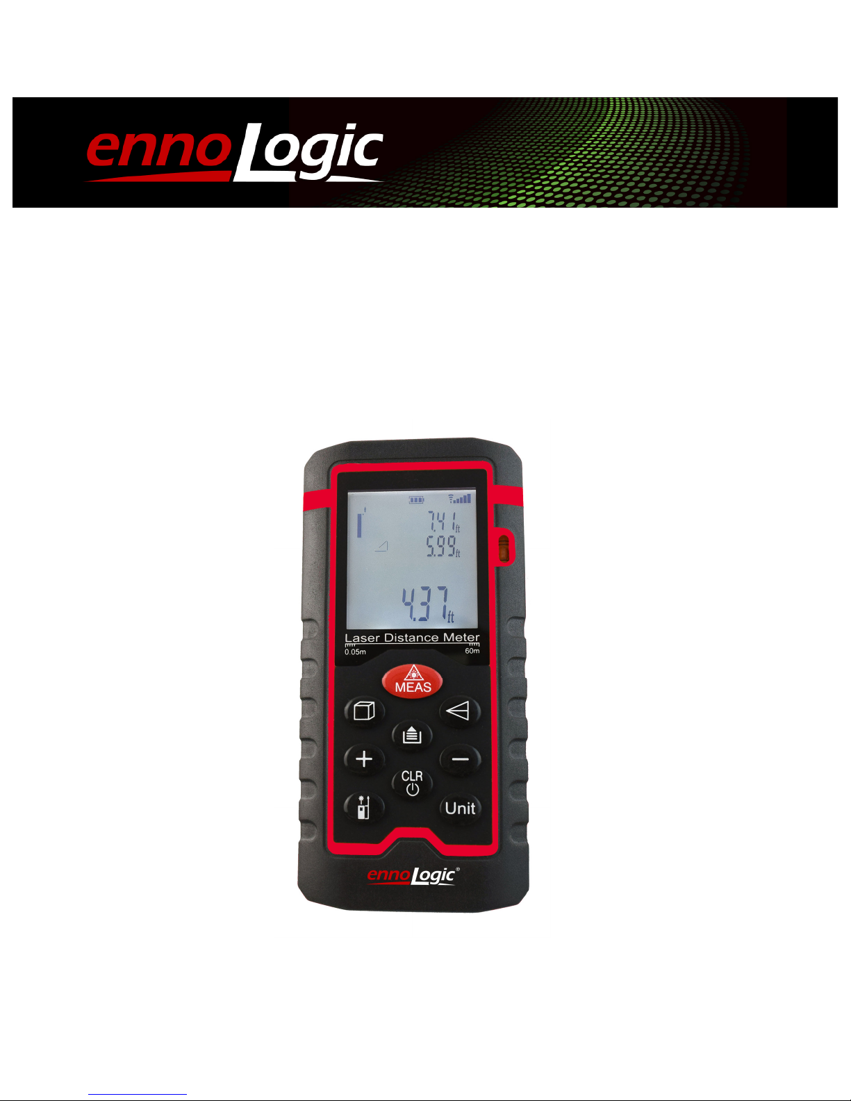
eD560L Laser Distance Meter
User Manual
Page 2

Laser Distance Meter ennoLogic eD560L
Made in China
User Manual Version 1.2. Revised 11/17/2017.
© 2017 ennoLogic™. All rights reserved.
http://ennologic.com
Page 3

Table of Contents
1. Overview ................................................................................................ 1
1.1 Important Notes, Safety Considerations and.............................. 1
Disclaimer – Please Read .................................................................... 1
1.2 LCD Display ................................................................................... 3
1.3 Keypad ............................................................................................ 4
1.4 Battery Installation or Replacement............................................. 4
1.5 How to Use Your Laser Distance Meter ...................................... 5
Power On/Off.................................................................................. 5
Canceling an Operation / Clearing Display ................................ 5
Switching Measurement Units...................................................... 5
Setting the Reference Edge of the Instrument for your
Measurements ................................................................................ 6
Backlight .......................................................................................... 7
Setting of Power-On Defaults and Optional Modes................... 7
Measurement Modes ........................................................................... 8
Distance Measurement .................................................................. 8
Area Measurement ....................................................................... 11
Volume Measurement ................................................................. 12
Indirect Measurements ................................................................ 13
Setting-Out Measurements ......................................................... 19
Reviewing Historical Data .......................................................... 20
SPECIFICATIONS ................................................................................... 22
Technical Specifications .................................................................... 22
Failure Causes and Solutions ........................................................... 23
Measurement Conditions ................................................................. 24
Maintenance ....................................................................................... 24
Page 4

1
1. Overview
Thank you for purchasing the ennoLogic eD560L laser distance
meter. This meter is a precision instrument designed to deliver
very accurate distance, area and volume measurements. It can
also measure height using the Pythagorean Theorem.
The eD560L laser distance meter is designed to meet the needs of
professionals engaged in surveying, construction, traffic, real
estate, urban planning, fire fighting, farm and garden. You will
also find it incredibly useful for many home improvement
projects.
1.1 Important Notes, Safety Considerations and
Disclaimer – Please Read
Please read these safety instructions and this user
manual carefully before using this instrument for the first time!
This meter is equipped with a single Class II infrared laser. Use
extreme caution when the laser pointer is on. Do not stare into the
beam. Never point the laser beam at anyone’s eyes, it can cause
permanent damage to the eyes. Do not reflect the laser beam off a
reflective surface and into someone’s eyes. Do not allow children
to use the instrument as a toy.
Page 5
2
Do not use the instrument in a flammable or explosive
environment. Do not use this meter in areas where it is prohibited
e.g. near airports and hospitals, or where it would be in violation
of the law.
To ensure proper operation avoid using this instrument in areas
with strong electromagnetic interference.
Do not open the instrument other than for the purpose of
replacing batteries.
Store the instrument at a cool and dry location and do not expose
it to high temperatures and humidity. Remove the batteries if the
meter will be out of use for an extended period. Do not clean the
instrument with corrosive or caustic cleaners. Treat the laser and
focusing lens as you would the optical lens of a camera.
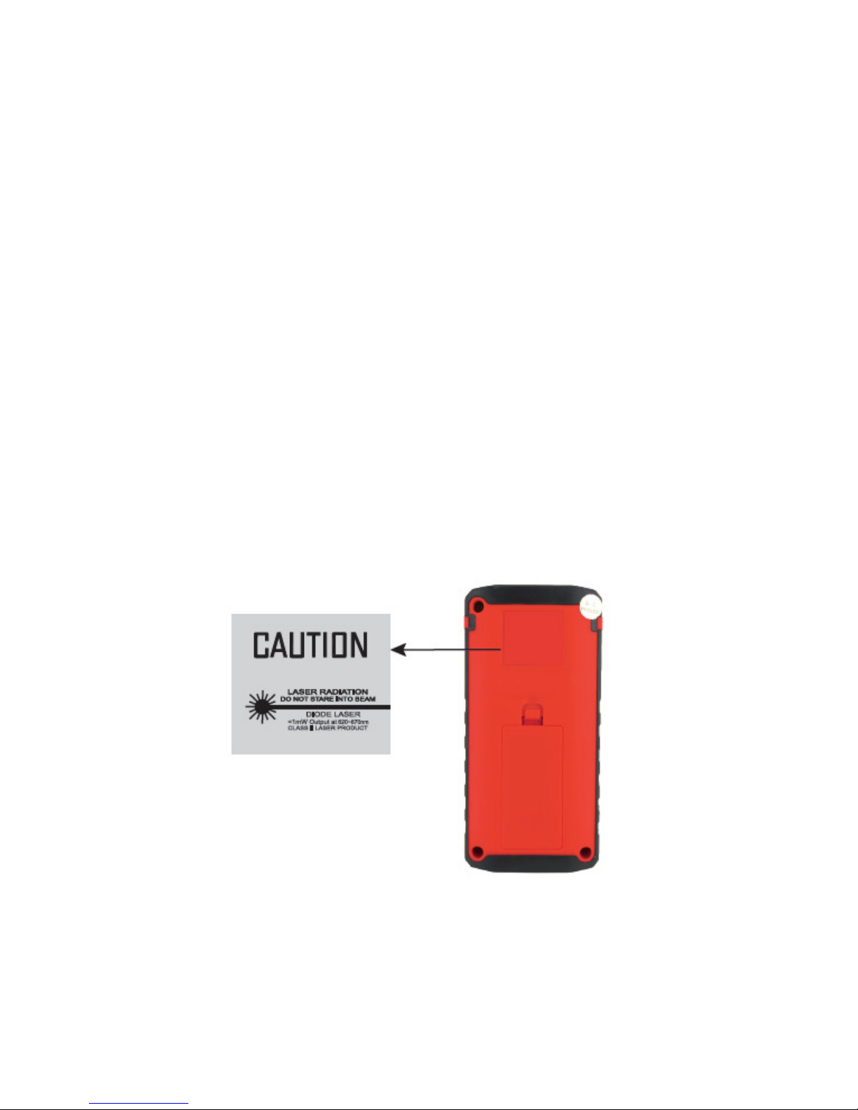
Location of Laser Warning Label
Page 6
3
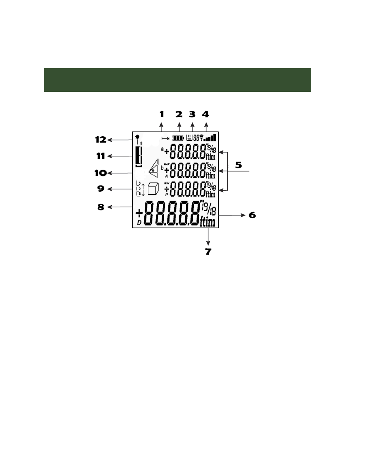
1.2 LCD Display
1 - Length measurement indicator
2 - Battery indicator
3 - Stored data indicator
4 - Signal strength indicator
5 - Secondary display area
6 - Main display area
7 - Measurement unit
8 - Area/Volume measurement mode
9 - Setting-out measurement mode
10 – Indirect measurement mode
11 - Measurement reference edge indicator
12 - Laser emission indicator
Page 7
4
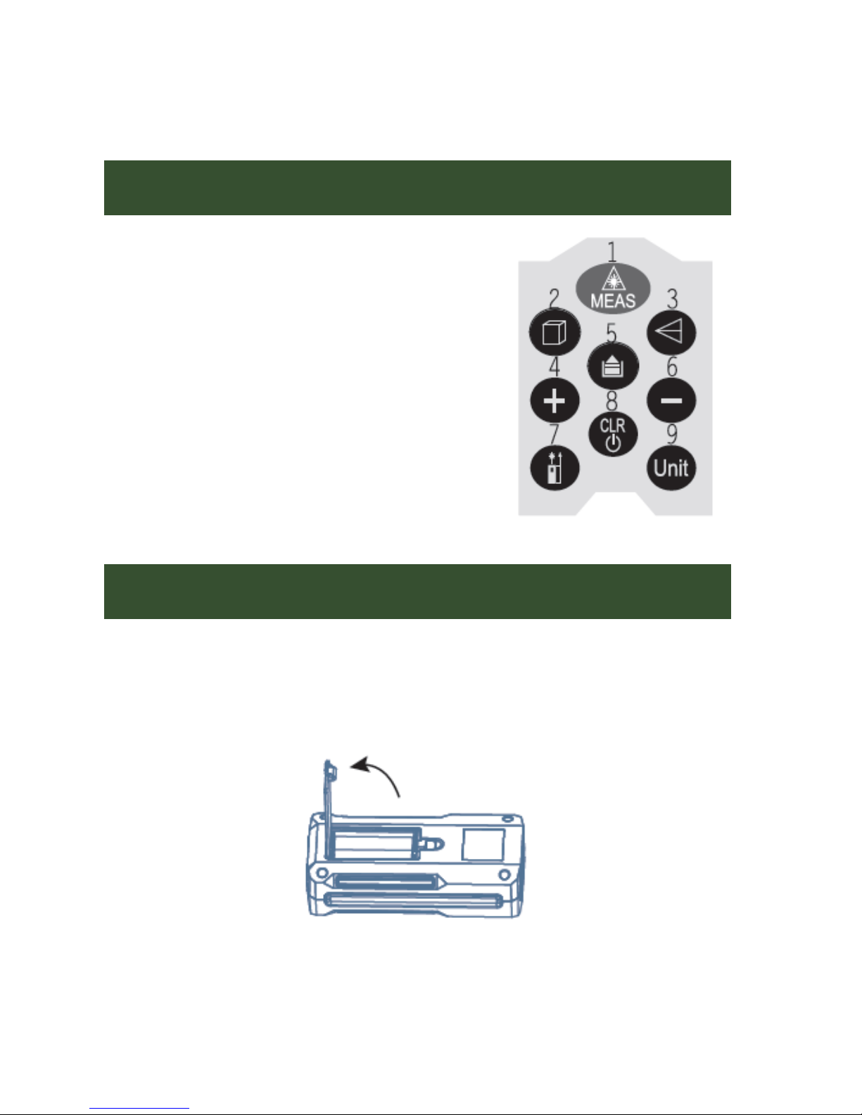
1.3 Keypad
1 - Power-on/Measurement key
2 - Volume/Area key
3 – Indirect Measurement (Pythagorean
Theorem)
4 - Plus (+) key
5 - Historical data key
6 - Minus (-) key
7 - Reference key / Backlight key
8 - Cancel/Power-off key
9 - Units key
1.4 Battery Installation or Replacement
Open the battery cover on the back of the instrument and install
two 1.5V AAA batteries according to polarity indicators (alkaline
batteries are recommended).
Page 8
5
1.5 How to Use Your Laser Distance Meter
Power On/Off
Press the MEAS key to turn on the instrument and laser.
Hold down the CLR key to turn the instrument off. It will
power off automatically after 3 minutes without use.
Canceling an Operation / Clearing Display
Press the CLR key to cancel the last operation or to clear
the display.
Switching Measurement Units
Press the Unit key to cycle through the measurement units
(meters, feet, and inches).
Setting Distance Area Volume
Meters 0.000 m 0.000 m2 0.000 m3
Feet 0.00 ft 0.00 ft2 0.00 ft3
Inches 0.0 in 0.00 ft2 0.00 ft3
Page 9
6
Setting the Reference Edge of the Instrument for your
Measurements
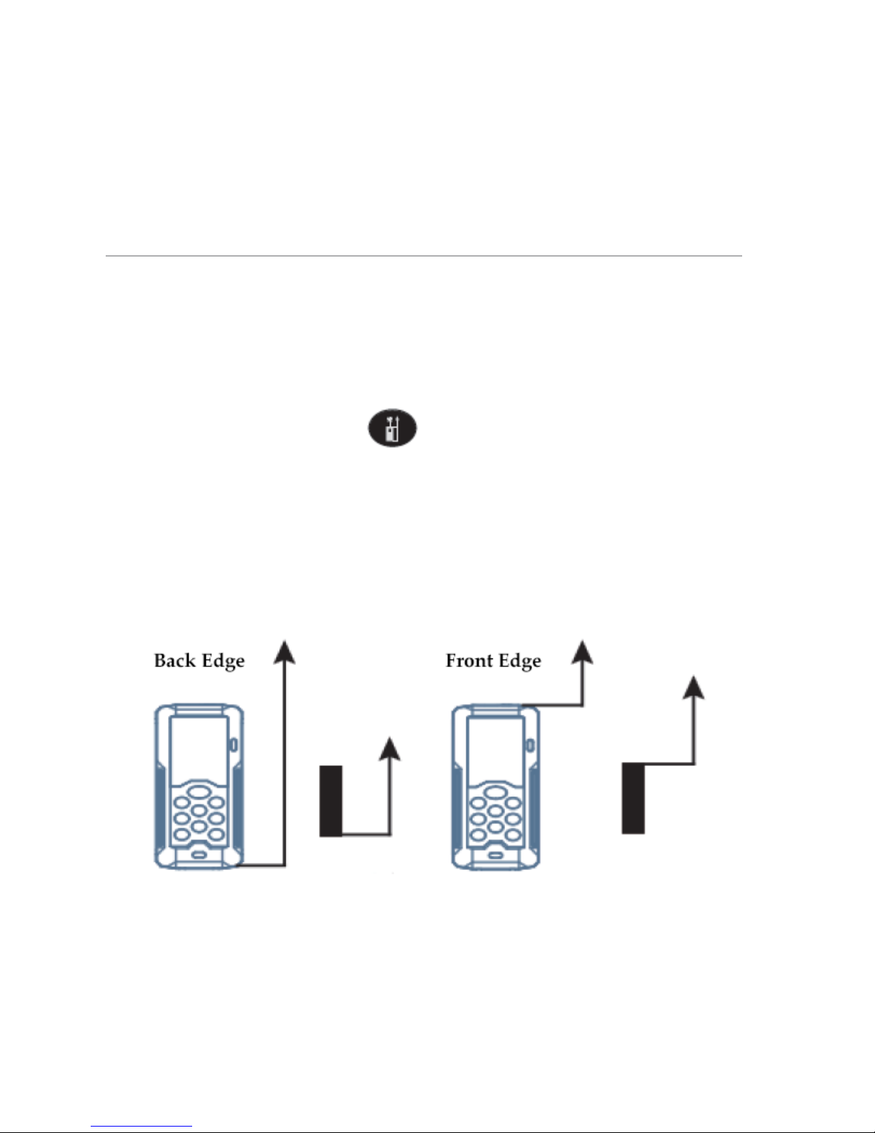
The default setting for the reference edge of the instrument is its
back edge. This means that any distance measurements you take
will be referenced to the back edge of the meter. You can choose
to use the front edge of the meter as the reference edge instead.
To do so, simply press the key, and the next measurement
will use the front edge as the measurement reference edge.
Pressing it again will change it back to the back edge. Changing of
the measurement reference edge will be confirmed by a beep.
Each time you turn the meter on, the measurement reference edge
will be set to the default value (back edge).
Page 10
7
Backlight
Hold down the key to turn the backlight on or off.
Setting of Power-On Defaults and Optional Modes
To change the power-on defaults and other optional modes turn
the meter on first, then hold down the key until the reference
edge/laser icon is displayed.
Press the key to cycle through the parameters that can be
changed (see table below).
To change the setting for a parameter, press the and
keys.
After changing a parameter, keep pressing the key until
the unit returns to normal measurement mode. This will save the
new settings.
Reference edge/laser icon: Use the “+” key to select whether the laser
will turn on automatically at power-on.
Area/volume and triangle icons: Use the “+” key to select whether
the laser will turn on automatically when entering area/volume or
triangle measurement mode.
Page 11

8
CAL 0
Use the “+” and “-“ keys to fine tune the
precision by up to ±7mm (offset).
bP. on/oFF
Use the “+” and “-“ keys to enable or
disable the beeper.
bL. on/oFF
Use the “+” and “-“ keys to select
whether the backlight turns on
automatically at power-on.
od. on/oFF
Use the “+” and “-“ keys to enable or
disable the outdoor signal enhanced
mode.
Measurement Modes
Distance Measurement
Press the key once to activate the laser. Press the key
again to trigger the measurement.
The measurement result will be displayed as soon as the
measurement is complete.
Page 12
9
Continuous Measurement and Maximum/Minimum Value
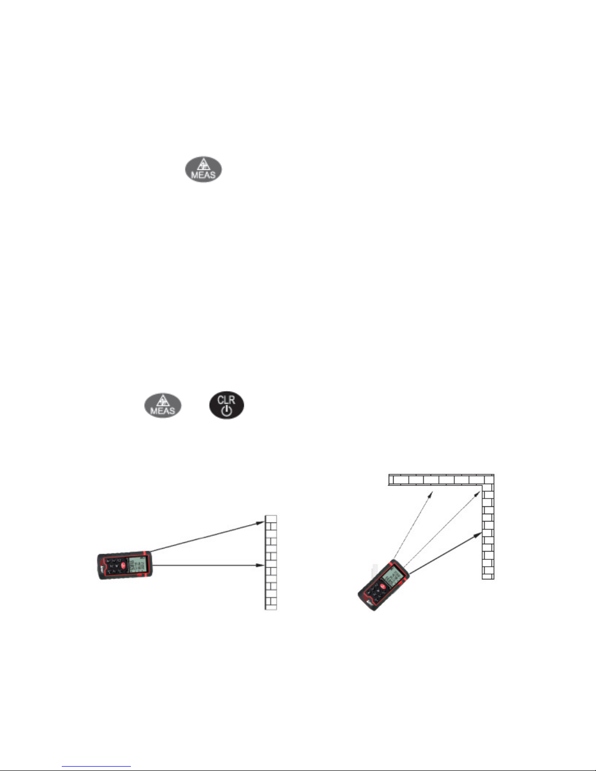
Hold down the key until you hear the beeper. This will
place the meter into continuous measurement mode. Use the laser
to scan the target area, e.g. a corner.
The continuous measurement mode allows you to determine the
maximum or minimum distance such as the measurement of a
diagonal distance (maximum value) or vertical distance
(minimum value) of a room.
The secondary display area will show the maximum and
minimum values and the main display area will show the realtime measurement value.
Press the or key to cancel continuous measurement
scanning.
Examples of continuous measurement
Page 13

10
Adding and Subtracting Multiple Distance Measurements
Addition: Take your first distance measurement. Then press the
key once. The first row of the secondary display area will
now show your initial measurement and the “+” sign. Any
subsequent measurements will now be added to the previous
one(s).
Subtraction: Take your first distance measurement. Then press the
key once. The first row of the secondary display area will
now show your initial measurement and the “-“ sign. Any
subsequent measurements will now be subtracted from the
previous one(s).
Press the key to cancel the last operation.
Press the key again to exit the mode of distance
measurement.
Page 14
11
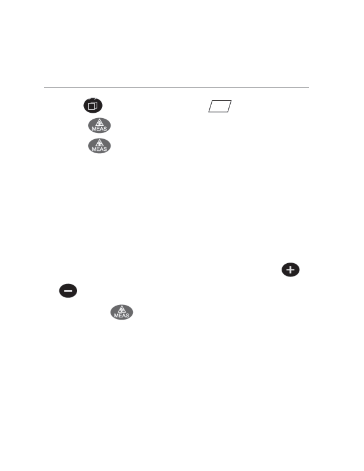
Area Measurement
Press the key once, you will see the icon.
Press the key to measure the first distance (e.g. length).
Press the key again to measure the second distance (e.g.
width).
The meter will calculate the area and show the result in the main
display area. The individual measurement results will be
displayed in the secondary display area.
Adding and Subtracting Multiple Area Measurements
After one area measurement has been completed, press the
or key and take another area measurement.
Then press the key and the main display will show the
sum (+) or difference (-) of the previous area measurement(s) and
the last measurement that was taken. The values of previous area
measurement(s) and last measurement will be shown in the
secondary display area.
Page 15
12
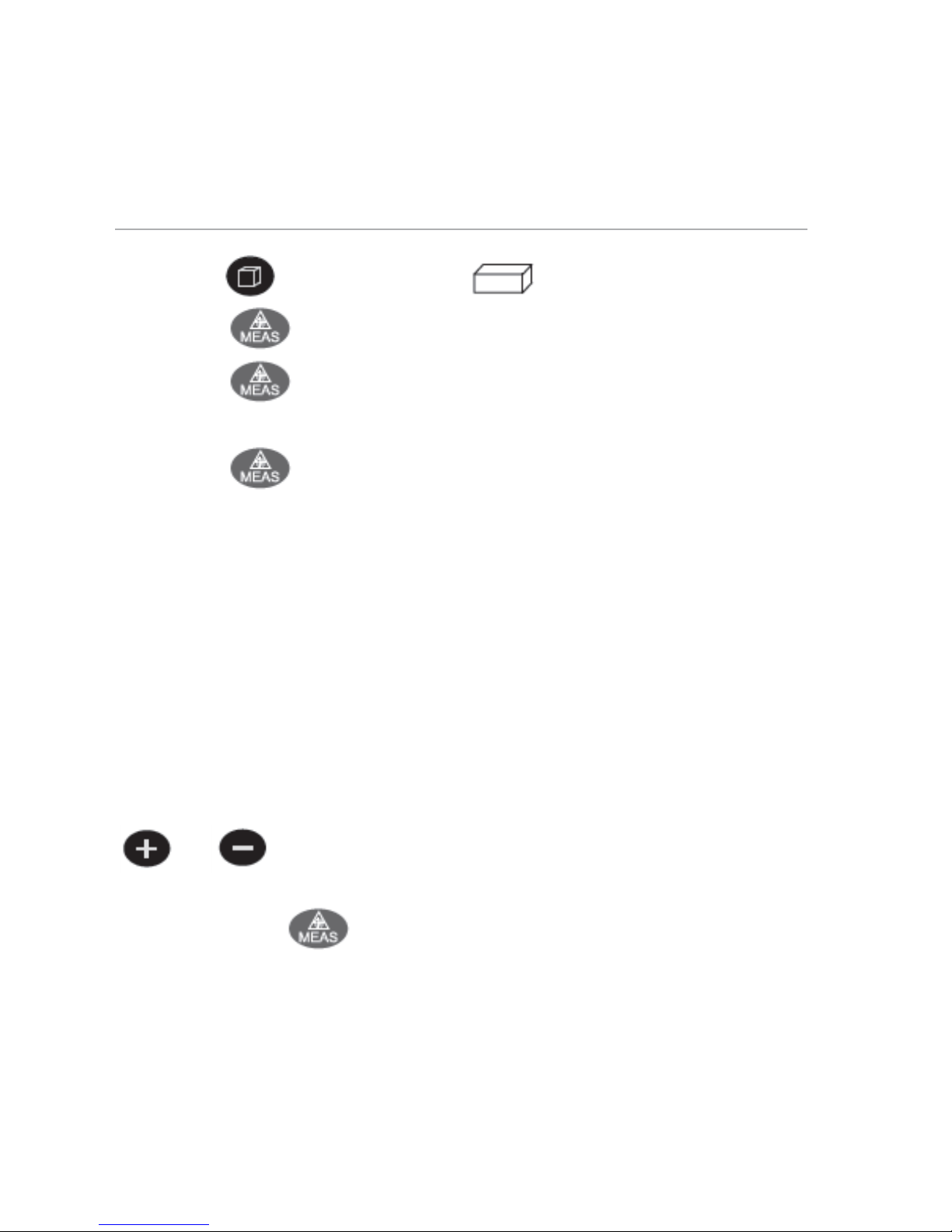
Volume Measurement
Press the key twice and the icon will be displayed.
Press the key to measure the first distance (e.g. length).
Press the key again to measure the second distance (e.g.
width).
Press the key a third time to measure the third distance
(e.g. height).
The meter will calculate the volume and show the result in the
main display area. The individual measurement results will be
displayed in the secondary display area.
Adding and Subtracting Multiple Volume Measurements
After one volume measurement has been completed, press the
or key and take another volume measurement.
Then press the key and the main display will show the
sum (+) or difference (-) of the previous volume measurement(s)
and the last measurement that was taken. The values of previous
volume measurement(s) and last measurement will be shown in
the secondary display area.
Page 16

13
Indirect Measurements
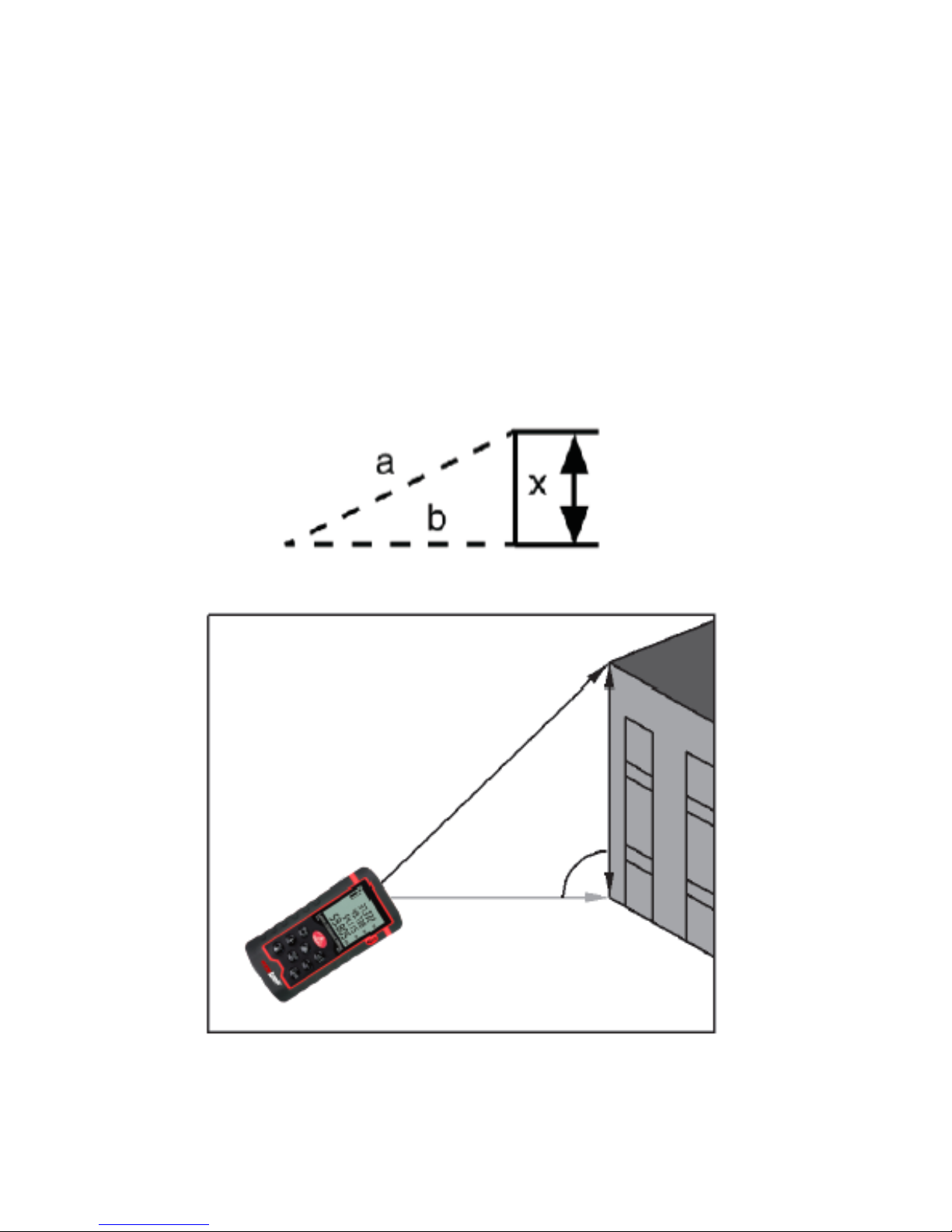
The instrument can calculate a distance with use of the
Pythagorean Theorem automatically. The Pythagorean Theorem
states that for a right triangle, the square of the hypotenuse (the
side opposite the right angle) is equal to the sum of the squares of
the other two sides. This function can be used to indirectly
measure places that are either hard to access or difficult to
measure directly with the meter (e.g. height of a building).
Indirect Measurement Mode 1:
The measurement of distance using the sides of a triangle requires
two measurements according to the following steps:
Press the key once and the icon will be displayed.
Follow the prompt of the flashing icon: press the
key to first measure the hypotenuse and then press it again to
measure the right-angle edge of the triangle.
(Note: when measuring the right-angle edge of the triangle, keep
the instrument as horizontal as possible.)
After these two measurements have been completed, the
Pythagorean calculation is performed automatically.
If the measurement results meet the requirements of the
Page 17
14
Pythagorean Theorem (the distance of the hypotenuse is longer
than the distance of the right-angle edges), the calculated length
of the third triangle side will be displayed in the main display
area. The measurement values of the hypotenuse and right-angle
edges will be displayed in the secondary display area.
Page 18
15
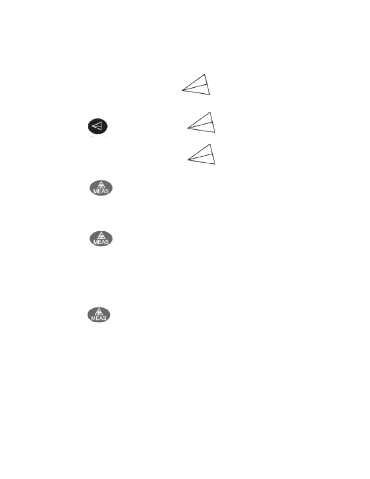
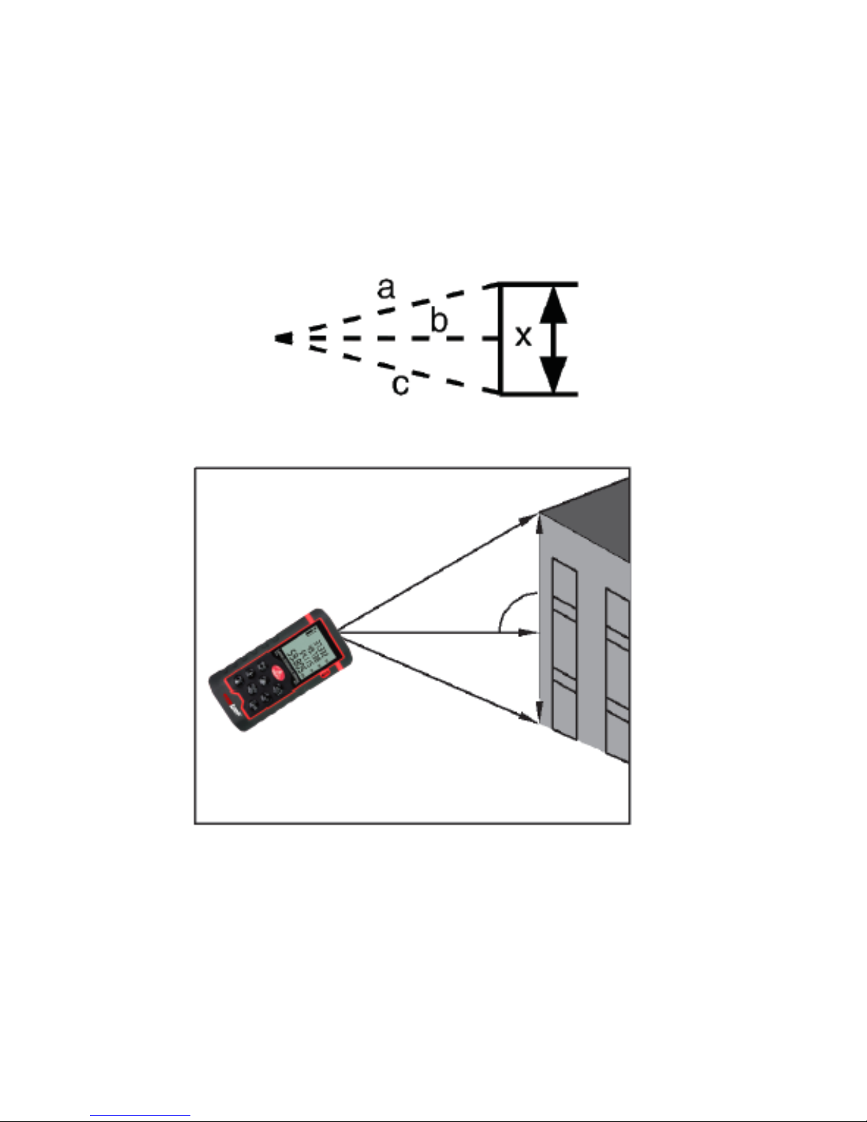
Indirect Measurement Mode 2:
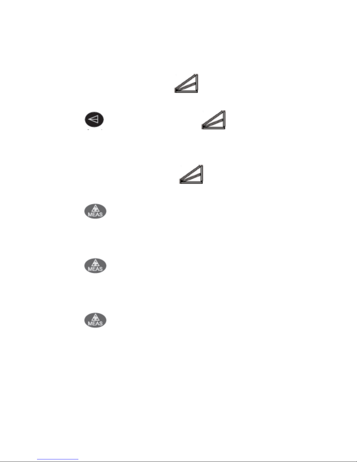
Press the key twice and the icon will be displayed.
Follow the prompt of the flashing icon:
Press the key once to measure the hypotenuse of the first
triangle (pointing upward).
Press the key again to measure the common right-angle
side of the two triangles. Keep the instrument as horizontal as
possible.
Press the key a third time to measure the hypotenuse of
the second triangle (pointing downward).
If the measurement result meets the requirements of the
Pythagorean Theorem, the calculated height x (see diagram
below) will be displayed in the main display area. The individual
Page 19
16
measurement values of the hypotenuse and right-angle sides (a, b,
and c) will be displayed in the secondary display area.
Page 20
17
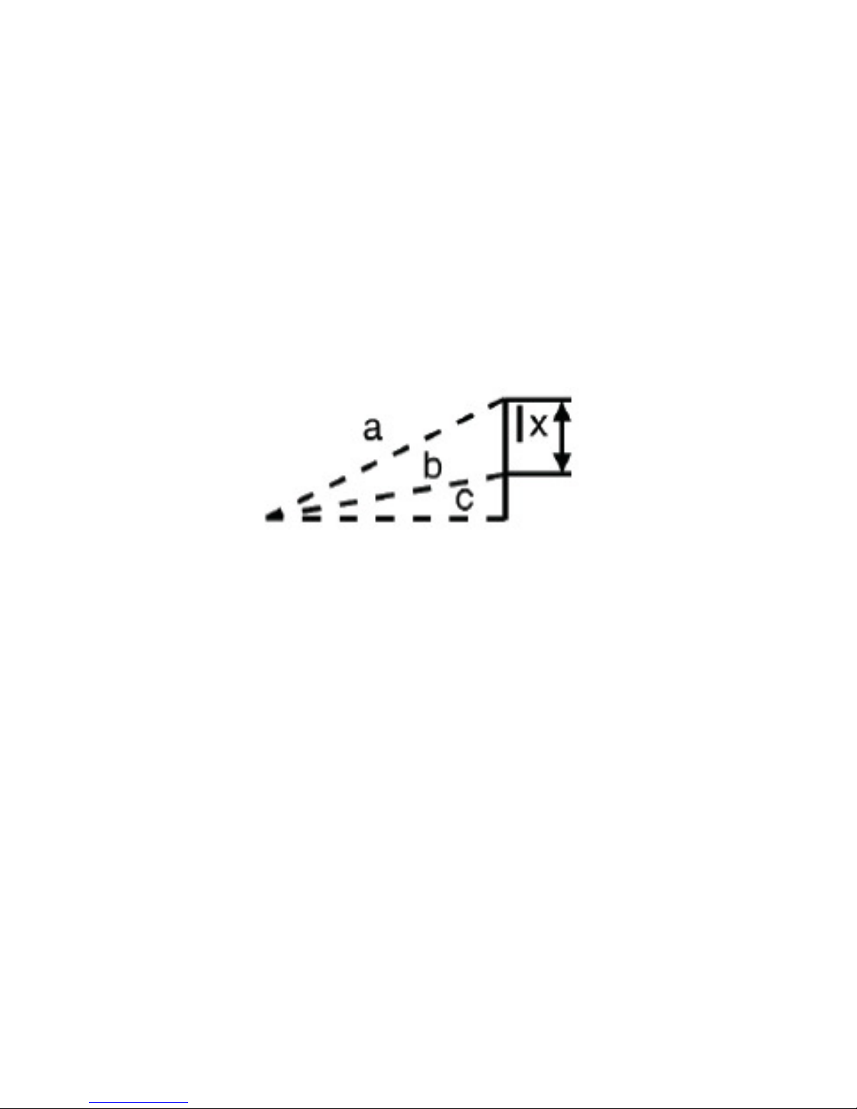
Indirect Measurement Mode 3:
Press the key three times and the icon will be
displayed.
Follow the prompt of the flashing icon:
Press the key once to measure the hypotenuse of the first
triangle.
Press the key again to measure the common side of the
two triangles.
Press the key a third time to measure the shared right-
angle side of the two triangles.
Page 21
18
If the measurement result meets the requirements of the
Pythagorean Theorem, the calculated height x (see diagram
below) will be displayed in the main display area.
The individual measurement values of the triangle sides will be
displayed in the secondary display area.
Note: when measurements are made in the Pythagorean mode,
the length of the right-angle side must be less than that of the
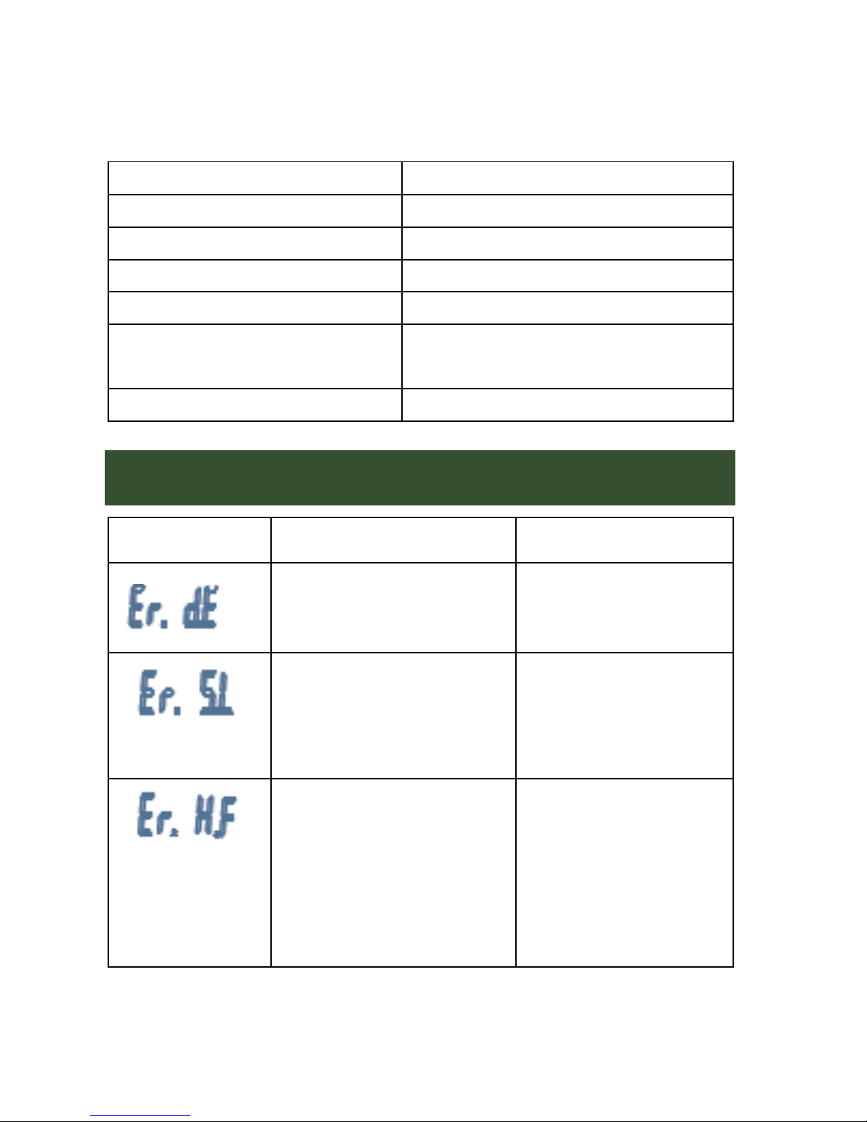
hypotenuse. Otherwise, the instrument will display a “calculation
error” (Er.dE).
Also, when using Pythagorean mode, ensure that all
measurements are made from the same starting point. When
measuring right-angle sides of triangles, make sure the right-
angle side is perpendicular to the measured surface.
Page 22
19
Setting-Out Measurements
Hold down the key to enter the setting-out function. First,
value a is being set, its second digit will flash. Select the desired
value for this digit by pressing the + and – keys (0 to 9). To change
digits, press the key. For every press of the key,
the selected digit moves one place to the right and finally cycles
back to the first digit. After you finished entering the value of a,
press the key again to start setting the value of b. After
value b has been set (using the same method as for value a), press
the key again to finish entering values for a and b, and to
enter the setting-out measurement mode.
After entering the setting-out mode, the third row of the
secondary display area shows the value of the set distance of the
Page 23

20
nearest setting-out point, the main display area shows the
distance from the current position to the setting-out point. A
positive value means the current position is larger than the
distance of the setting-out point and a negative value means it is
less. If the distance from the nearest setting-out point is less than
0.1m (0.33ft), the meter begins to beep. As the setting-out position
is approached, the sound of the beeper changes noticeably. The
distance of the setting-out point is a + (b×n), where “n” is a non-
zero integer number.
Press the key or key to end the setting-out mode.
Reviewing Historical Data
Press the key to enter the history data mode where you can
review the last 20 measurements (automatically stored). Press the
and keys to cycle through the data of the last 20
Page 24

21
measurements. The latest measurement will automatically be
added to the end of the data buffer at storage location 20. All
other values will be shifted down by one storage location towards
1, so that the buffer always contains the last 20 measurements.
Page 25

22
SPECIFICATIONS
Technical Specifications
Measurement range 0.05 – 60m
Measurement accuracy 土 2 mm
Measurement unit Meters, Feet, Inches
Laser class Class II
Laser type 620~670nm, <1mW
Calculation of area and
volume
√
Measurement with
Pythagorean Theorem
√
Adding and subtracting
measurements
√
Maximum/minimum value
measurement
√
Continuous measurement √
Backlight √
Multiline display √
Beeper √
Setting-out function √
Standard function √
Historical data memory 20 measurements
Operating temperature 0℃---40℃ (32℉---104℉)
Page 26
23
Storage temperature -20℃---60℃(-4℉--- 140℉)
Battery life 5000 measurements
Battery: 2x 1.5V AAA alkaline batteries
Backlight auto power-off 35 seconds
Instrument auto power-off 3 minutes
Size 116 x 56 x 32 mm (4.6 x 2.2 x 1.3
in.)
Weight 100g (3.5oz.)
Failure Causes and Solutions
Error Code Causes Solution
Calculation error Measure again
The received signal is
too weak and the
measurement time is
long.
Use a sighting
device
Hardware failure
Power the
instrument on and
off multiple times.
If the error persists,
please contact
ennoLogic.
Page 27

24
Measurement Conditions
Operating the instrument in extreme environmental conditions
may cause substantial errors. Examples include bright sunshine,
extreme temperatures, poor surface reflections and low batteries.
Under these conditions applying a reflective sheet to the target
surface may improve results.
Transparent or clear measurement target surface (such as water,
clear glass, etc.) may lead to inaccurate measurements.
Inaccurate measurements can also result if the target surface
reflects light strongly.
Very dark surfaces or surfaces that do not reflect light well can
cause longer measurement times.
Maintenance
Do not store the instrument in environments of high temperature
and/or humidity. Remove the batteries if the meter will be out of
use for an extended period and stored it in a cool and dry place.
Keep the instrument surface clean. Do not clean the instrument
with corrosive or caustic cleaners. Treat the laser and focusing
lens as you would the optical lens of a camera.
Page 28

25
ennoLogic.com
PO Box 25207
Eugene, OR 97402
 Loading...