

Ennera Windera S Installation & Maintenance Manual

Code: I.H4.V10.3003
Installation and Maintenance Manual Version: 07
Installation and Maintenance
Manual
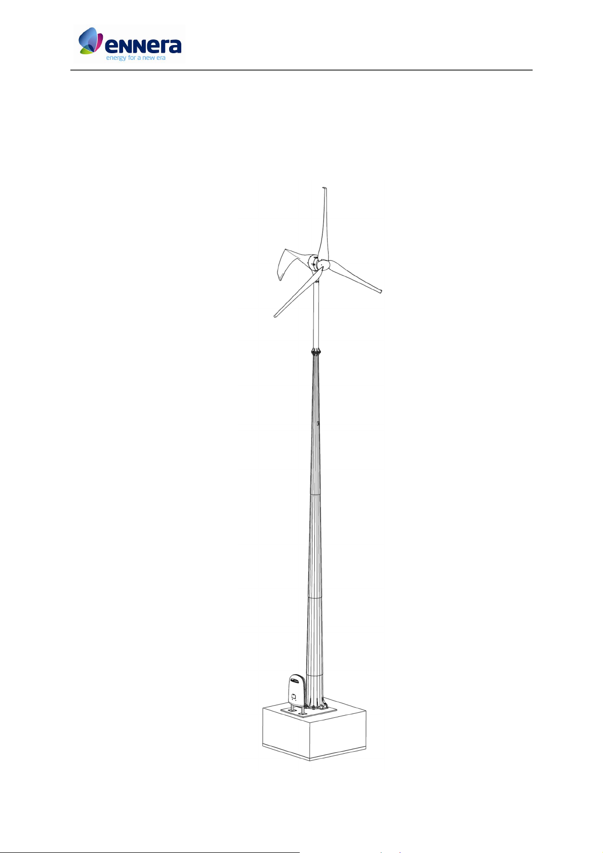
Windera S wind turbine
Ennera Energy and Mobility S.L.
1 / 66
This document contains confidential information which is property of Ennera Energy and Mobility, S.L. The copy, transmission or use by other people, of the whole document or
part of its contents, is not allowed without written permission from Ennera Energy and Mobility S.L.
Ennera Energy and Mobility, S.L.

Code: I.H4.V10.3003
Installation and Maintenance Manual Version: 07
CONTENTS
1. INTRODUCTION ...................................................................................................................4
1.1. Aim ..............................................................................................................................4
2. PRIOR CONSIDERATIONS ....................................................................................................5
3. PACKING LIST ......................................................................................................................5
4. LIST OF ASSEMBLY TOOLINGS .............................................................................................6
4.1. Foundation ..................................................................................................................6
4.2. Elevation ......................................................................................................................6
4.3. Tower assembly ...........................................................................................................7
4.4. Wind turbine assembly ................................................................................................7
5. INSTALLATION .....................................................................................................................8
5.1. Foundation ..................................................................................................................8
5.2. Ennera design multi-section tower assembly ............................................................. 13
5.3. Ennera design 2-section tower assembly .................................................................... 17
5.4. Ambor design 3 section tower assembly .................................................................... 17
5.5. Lifting mechanism ...................................................................................................... 17
5.6. Anemometer installation ........................................................................................... 21
5.7. Small Wind Turbine assembly .................................................................................... 21
5.7.1. Windera S packaging ........................................................................................................................ 21
5.7.2. Yaw.................................................................................................................................................. 22
5.7.3. Generator ........................................................................................................................................ 23
5.7.4. Rotor................................................................................................................................................ 24
5.7.5. Tail .................................................................................................................................................. 26
5.8. Electrical connections ................................................................................................ 26
5.8.1. Converter set .................................................................................................................................... 26
5.8.2. Cable connections............................................................................................................................. 28
5.8.3. Electrical scheme .............................................................................................................................. 31
5.8.4. Anemometer .................................................................................................................................... 31
5.9. Wind turbine erection ................................................................................................ 32
6. SCREW KITS ....................................................................................................................... 35
6.1. Tower assembly kit .................................................................................................... 35
6.2. Wind turbine assembly kit ......................................................................................... 35
6.3. Anemometer assembly kit ......................................................................................... 36
6.4. Converter assembly kit............................................................................................... 36
7. COMMISSIONING .............................................................................................................. 36
7.1. Load new firmware .................................................................................................... 36
7.2. Change parameters .................................................................................................... 37
2 / 66
This document contains confidential information which is property of Ennera Energy and Mobility, S.L. The copy, transmission or use by other people, of the whole document or
part of its contents, is not allowed without written permission from Ennera Energy and Mobility S.L.
Ennera Energy and Mobility, S.L.

Code: I.H4.V10.3003
Installation and Maintenance Manual Version: 07
8. MAINTENANCE.................................................................................................................. 41
8.1. Safety procedures ...................................................................................................... 41
8.2. Routine inspections ................................................................................................... 41
8.3. Maintenance plan ...................................................................................................... 42
9. TROUBLESHOOTING .......................................................................................................... 43
10. FREQUENTLY ASKED QUESTIONS .................................................................................. 43
11. RECYCLING .................................................................................................................... 44
12. LOGBOOK ...................................................................................................................... 45
13. ANNEX 1: GENERAL DIMENSIONS DRAWING ................................................................ 46
14. ANNEX 2: SINGLE LINE DIAGRAM .................................................................................. 47
15. ANNEX 3: ELECTRICAL SCHEME ..................................................................................... 48
16. ANNEX 4: INSTALLATION CONTROL FORM .................................................................... 49
17. ANNEX 5: MAINTENANCE CONTROL FORM ................................................................... 52
18. ANNEX 6: INSTALLATION DRAWINGS ............................................................................ 54
19. ANNEX 7: LIST OF ALARMS ............................................................................................ 63
3 / 66
This document contains confidential information which is property of Ennera Energy and Mobility, S.L. The copy, transmission or use by other people, of the whole document or
part of its contents, is not allowed without written permission from Ennera Energy and Mobility S.L.
Ennera Energy and Mobility, S.L.
Code: I.H4.V10.3003
Installation and Maintenance Manual Version: 07
1. INTRODUCTION
1.1. Aim
This Installation and Maintenance Manual describes the procedures to be carried out in order to
satisfy the requirements of the installation and maintenance process of the Windera S small wind
turbine (SWT).
4 / 66
This document contains confidential information which is property of Ennera Energy and Mobility, S.L. The copy, transmission or use by other people, of the whole document or
part of its contents, is not allowed without written permission from Ennera Energy and Mobility S.L.
Ennera Energy and Mobility, S.L.
Code: I.H4.V10.3003
Installation and Maintenance Manual Version: 07
2. PRIOR CONSIDERATIONS
ONLY TRAINED PERSONNEL SHOULD INSTALL A WINDERA S WIND TURBINE.
A wrong installation of the turbine could lead to a serious damage.
Read this procedure carefully before starting any installation.
The Windera S wind turbine must not be installed with a wind speed average greater
than 10m/s. The loads at this wind speed could cause damage in the tower base and
pivoting point.
During wind turbine installation, the area surrounding the wind turbine should be free of people
not related with the installation.
FAILURE TO FOLLOW THE PROCEDURES DESCRIBED IN THIS MANUAL CAN CAUSE
SERIOUS INJURY.
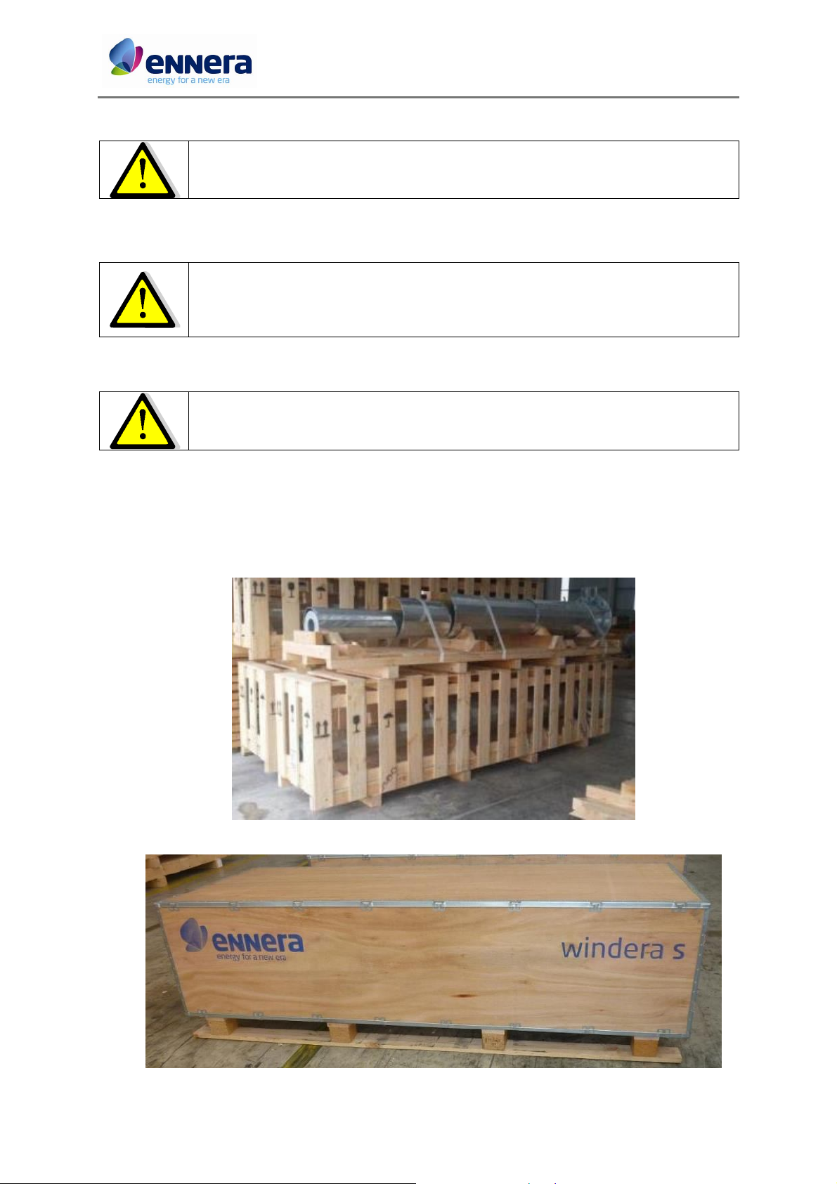
3. PACKING LIST
The Windera S small wind turbine is supplied in 2 packages: One with the tower and one with
the wind turbine.
5 / 66
This document contains confidential information which is property of Ennera Energy and Mobility, S.L. The copy, transmission or use by other people, of the whole document or
part of its contents, is not allowed without written permission from Ennera Energy and Mobility S.L.
Ennera Energy and Mobility, S.L.
Code: I.H4.V10.3003
Installation and Maintenance Manual Version: 07
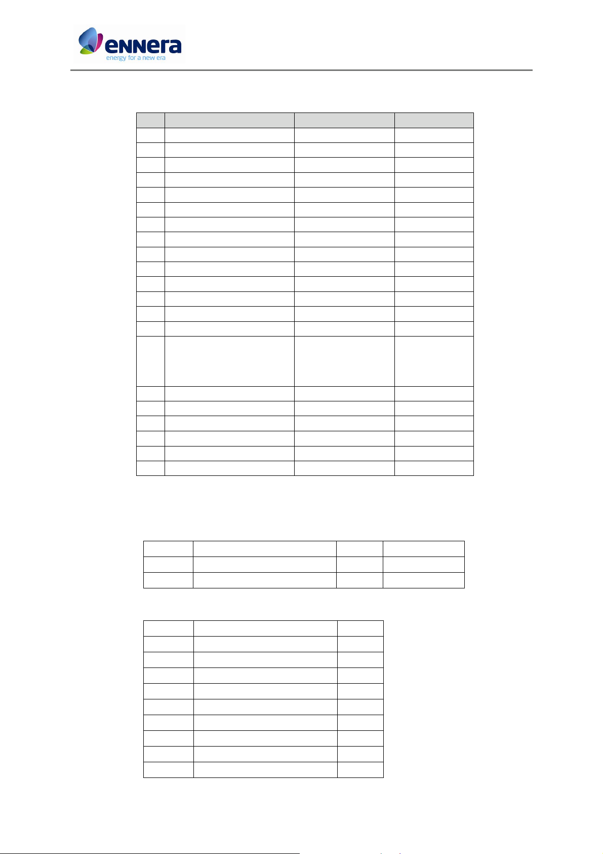
Inside the wind turbine package there are the following components:
COMPONENT CODE UNITS
W1 Generator JI.H4.G5.4000.00 1
W2 Brake JI.H4.K5.4000.00 1
W3 3 blade set JI.H4.B5.4000.01 1
W4 Converter JI.H4.P5.4000.01 1
W5 Tail JI.H4.N5.4000.01 1
W6 Yaw JI.H4.Y5.4000.00 1
W7 Tower cable (3x6mm2) JI.H4.P5.4000.05 1
W8 Cone JI.H4.B5.4000.05 1
W9 Hub JI.H4.B5.4000.04 1
W10 Hub bushing JI.H4.B5.4000.06 1
W11 Blade fixing plate JI.H4.B5.4000.07 3
W12 Yaw cover JI.H4.Y5.4000.50 1
W13 Converter housing JI.H4.P5.4000.04 1
W14 Converter structure JI.H4.P5.4000.02 1
JI.H4.V5.4000.03
W15 Screw kits (4 ref.)
JI.H4.P5.4000.07
JI.H4.T5.4000.05
JI.H4.T5.4000.13
W16 Earthing cable JI.H4.P5.4000.06 1
W17 Elevation cable 8.3m JI.H4.T5.4000.06 1
W18 Shackle 3.25Tn JI.H4.T5.4000.10 1
W19 Anemometer JI.H4.T5.4000.11 1
W20 Anemometer structure JI.H4.T5.4000.12 1
W21 Nameplate JI.H4.V5.4000.06 1
1
1
1
1
4. LIST OF ASSEMBLY TOOLINGS
4.1. Foundation
Reference Tooling Nº units Drawing
FD-1 Tower bolts 8 JI.H4.T5.4000.04
FD-2 Bolts position tooling 1 JI.H4.V10.4000.51
4.2. Elevation
Reference Tooling Nº units
EL-1 Tractel ground fixing point 1
EL-2 Fixing point tooling 1
EL-3 Tractel 1600 kg 1
EL-4 Shackle 3.25Tn 2
EL-5 Tractel cable 15m 1
EL-6 GinPole Ø114.3mm, L=4m 1
EL-7 Hydraulic jack 2
EL-8 Hexagon bolt M20x180 1
EL-9 Spanner 46 1
6 / 66
This document contains confidential information which is property of Ennera Energy and Mobility, S.L. The copy, transmission or use by other people, of the whole document or
part of its contents, is not allowed without written permission from Ennera Energy and Mobility S.L.
Ennera Energy and Mobility, S.L.
Code: I.H4.V10.3003
Installation and Maintenance Manual Version: 07
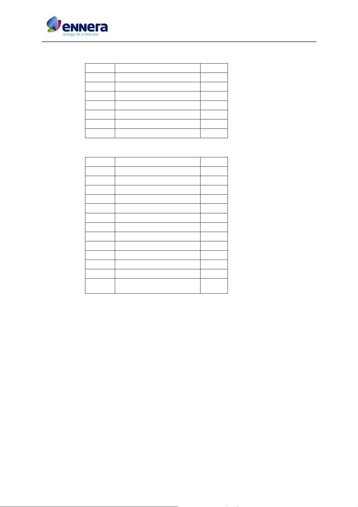
4.3. Tower assembly
Reference Tooling Nº units
TW-1 Ratchet tensioner 15m 2
TW-2 Metallic mallet 1
TW-3 Molykote spray (grease) 1
TW-4 Cable guide 1
TW-5 Galvanizing spray 1
TW-6 Level 2
TW-7 Trestle 1
4.4. Wind turbine assembly
Reference Tooling Nº units
WT-1 Allen keys 1
WT-2 Torque wrench 30-200Nm 1
WT-3 Spanner nº 17 1
WT-4 Spanner nº 19 1
WT-5 Spanner nº 50 1
WT-6 Loctite 243 Threadlocker 1
WT-7 Rotor extraction M20 screw 1
WT-8 Ratchet set with sockets 1
WT-9 Round file Ø10mm 1
WT-10 Screwdriver set 1
WT-11 RAL 9003 matt colouring spray 1
WT-12 Galvanizing spray 1
Set of steel inserts for aluminium
WT-13
(Helicoil type-M5, M6, M8, M10)
1
7 / 66
This document contains confidential information which is property of Ennera Energy and Mobility, S.L. The copy, transmission or use by other people, of the whole document or
part of its contents, is not allowed without written permission from Ennera Energy and Mobility S.L.
Ennera Energy and Mobility, S.L.
Code: I.H4.V10.3003
Installation and Maintenance Manual Version: 07
5. INSTALLATION
5.1. Foundation
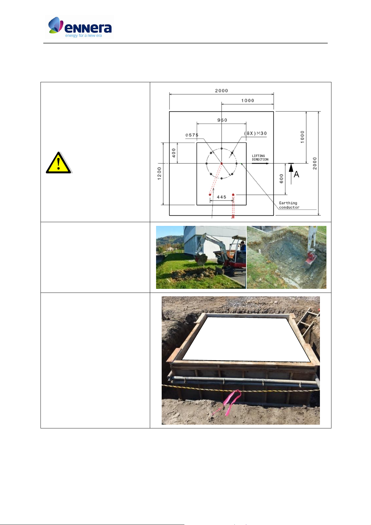
See drawing JI.H4.V10.4000 (Annex 4)
for foundation construction details.
The foundation must be
done at least 3 weeks
before wind turbine
installation.
1. Make a hole of 2x2m and 1m depth.
2. If the soil is not consistent, make a
box of wood to sustain the walls of the
hole.
8 / 66
This document contains confidential information which is property of Ennera Energy and Mobility, S.L. The copy, transmission or use by other people, of the whole document or
part of its contents, is not allowed without written permission from Ennera Energy and Mobility S.L.
Ennera Energy and Mobility, S.L.
Code: I.H4.V10.3003
lifting direction
Installation and Maintenance Manual Version: 07
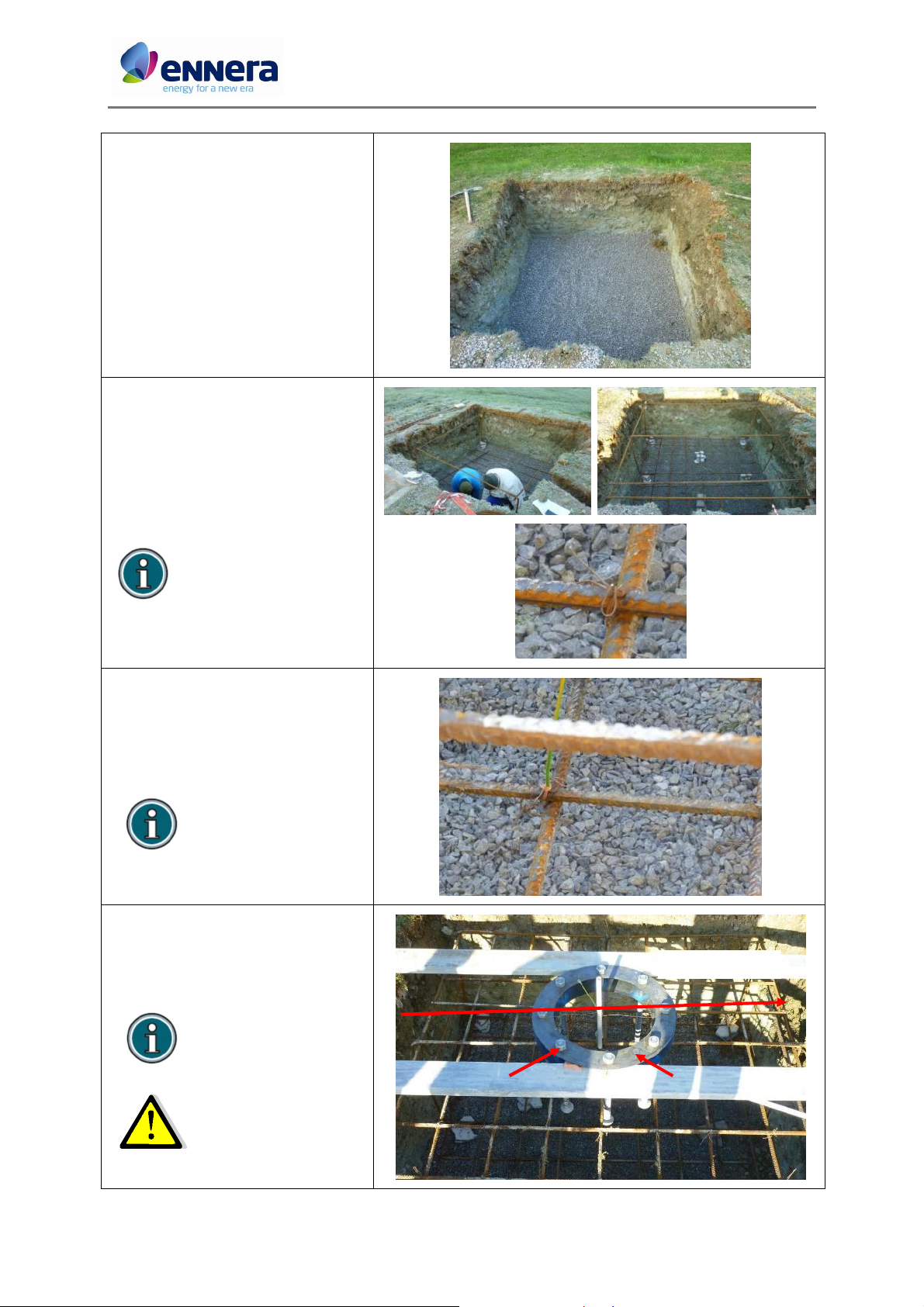
3. Add a 75mm of thick plain cement
concrete layer.
4. Place the foundation reinforcement
steel bars inside the hole, fixing the bars
between them with metallic wire (up
and bottom).
Lower reinforcement at a
distance of 100mm from
plain cement concrete.
5. Attach an earthing cable of 6mm2 to
the bottom part of the reinforcement
bars.
(Foundation earthing
cable not supplied.
Length = 2m)
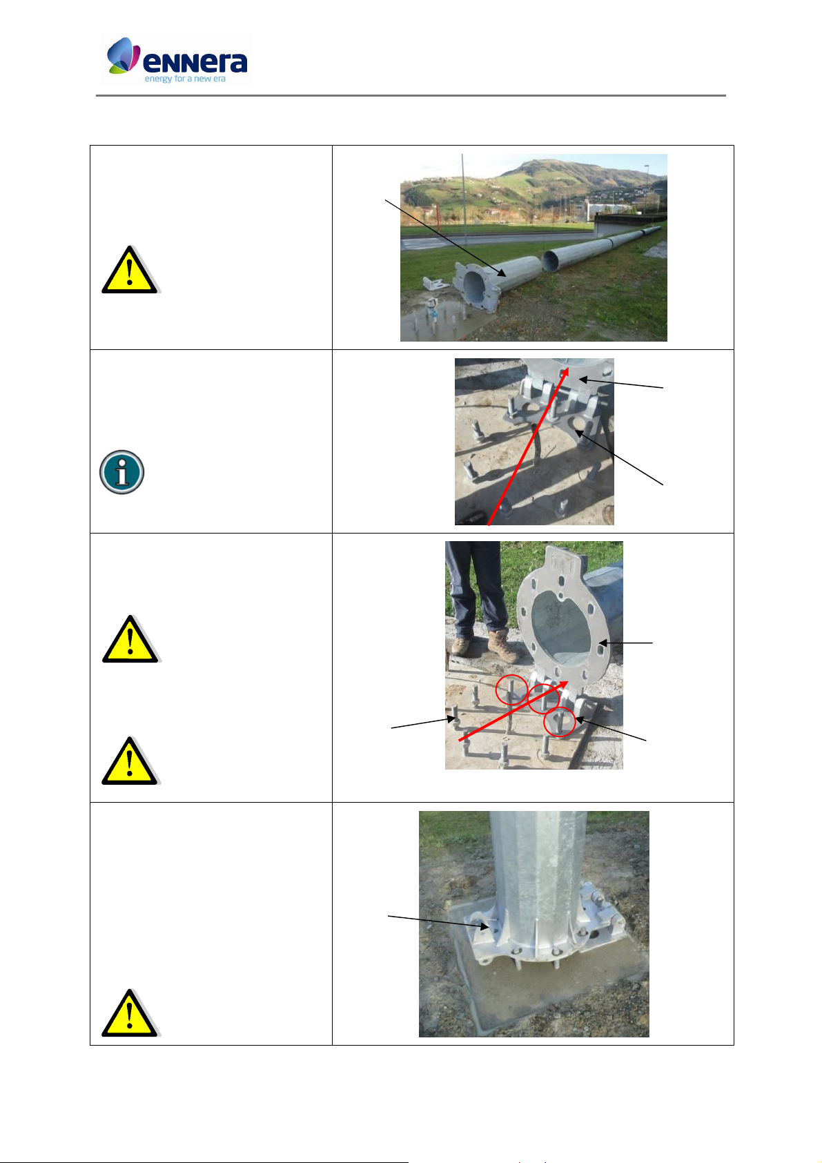
6. Place the 8xM30 fixing steel bolts
(FD-1) with the template (FD-2), so that
the 8 bars are perfectly vertical and
concentrically to tower axis.
Follow dimension of the
drawing “Bolts position
tooling” in Annex 4.
FD-1 FD-2
2 bolts must be aligned
with the lifting direction.
After placing the template, level it.
9 / 66
This document contains confidential information which is property of Ennera Energy and Mobility, S.L. The copy, transmission or use by other people, of the whole document or
part of its contents, is not allowed without written permission from Ennera Energy and Mobility S.L.
Ennera Energy and Mobility, S.L.

Code: I.H4.V10.3003
Installation and Maintenance Manual Version: 07
7. Place the Ø32mm corrugated tube.
One from the tower axis to the
converter and the other from the
converter to the grid connection point.
Avoid sharp corners in the
corrugated tube.
8. The other part of the earthing
conductor must be out of the
foundation at least 1m, from the middle
point of the fixing bolts.
9. Review the levelling of the template
with the bolts and the lifting direction.
10 / 66
This document contains confidential information which is property of Ennera Energy and Mobility, S.L. The copy, transmission or use by other people, of the whole document or
part of its contents, is not allowed without written permission from Ennera Energy and Mobility S.L.
Ennera Energy and Mobility, S.L.

Code: I.H4.V10.3003
Installation and Maintenance Manual Version: 07
10. Pour the concrete inside the hole.
Reinforced Cement Concrete (minimum
30N/mm2 at 28 days).
11. During the concrete pouring, review
the levelling of the template with the
bolts and the lifting direction.
12. Finish pouring the concrete until it
has reached the mark in the bolts
(185mm of the bolt out of the concrete)
and vibrate the concrete.
13. Review the levelling and the
alineation of the bolts.
In case the top surface
finishing is good, 160mm of
the bolt out of the
concrete.
11 / 66
This document contains confidential information which is property of Ennera Energy and Mobility, S.L. The copy, transmission or use by other people, of the whole document or
part of its contents, is not allowed without written permission from Ennera Energy and Mobility S.L.
Ennera Energy and Mobility, S.L.

Code: I.H4.V10.3003
160mm
Installation and Maintenance Manual Version: 07
14. In case the top surface finishing of
the foundation is good (flat and
smooth), the foundation is finished.
15. In case the finishing of the top
surface is not good, a final layer must be
added.
16. When the concrete is cured, remove
the fixing bolts template. Make a
rectangle of wood and pour a 25mm
layer with non shrink grout according to
the drawing.
The bolt must have 160mm
out of the non shrink grout.
17. Take away, with the help of a
hammer, the 4 pieces of wood located
around the foundation and cover the
concrete area with the soil removed
from the hole.
12 / 66
This document contains confidential information which is property of Ennera Energy and Mobility, S.L. The copy, transmission or use by other people, of the whole document or
part of its contents, is not allowed without written permission from Ennera Energy and Mobility S.L.
Ennera Energy and Mobility, S.L.
Code: I.H4.V10.3003
T0T1
Lifting
direction
T0 T1 FD-1
Installation and Maintenance Manual Version: 07
5.2. Ennera design multi-section tower assembly
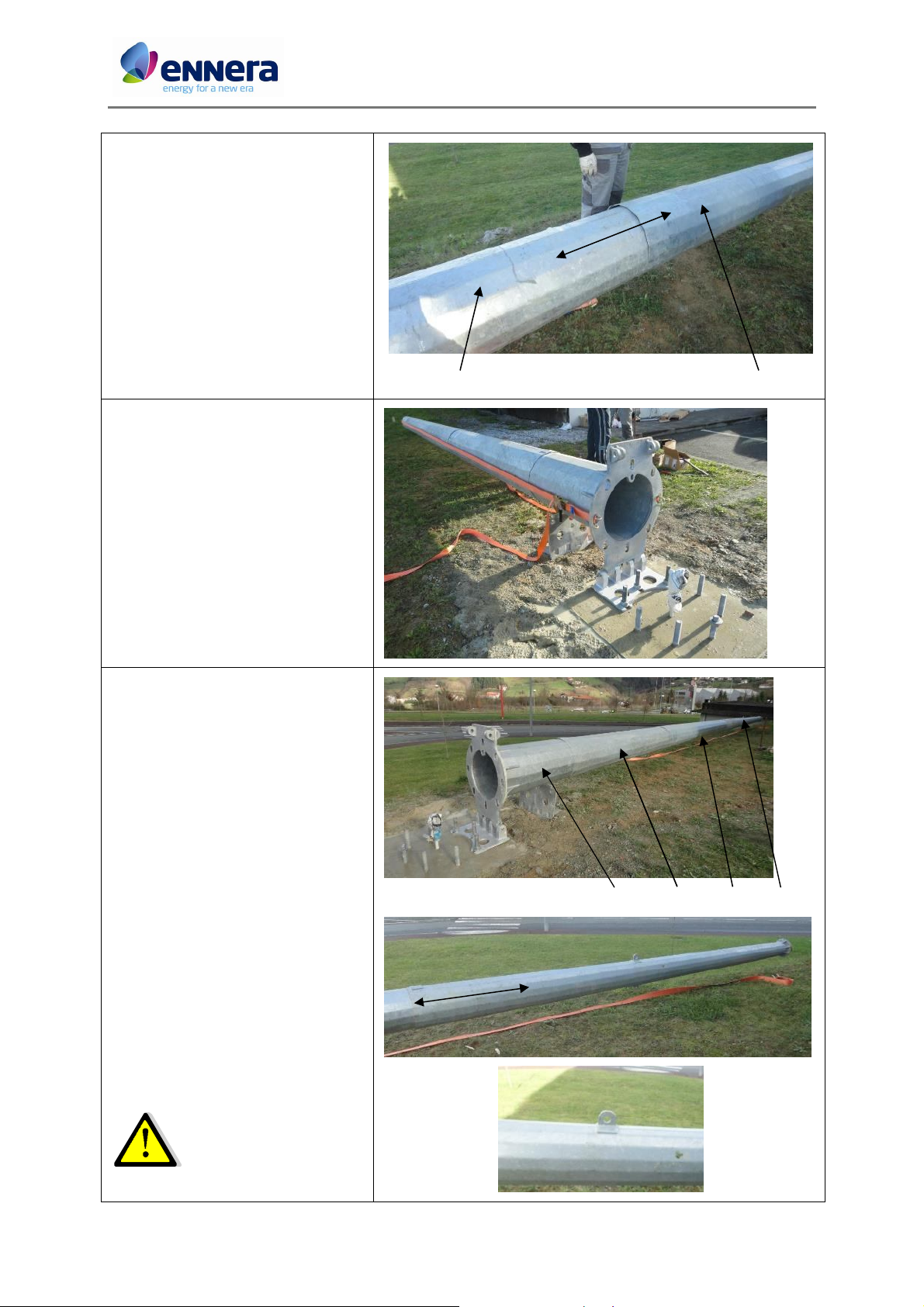
First
section
1. Put the tower sections in a
sequential way close to the foundation.
The tower first section
should be located next to
the foundation.
2. Join the first section and the tower
base plate with the J bolt M20x500 as
shown in the figure.
Place the base plate in the
middle of the lifting
direction as shown in the
figure.
3. Place the first section and the tower
base plate over the foundation bolts
(FD-1) as shown in the figure.
Make sure that the base
plate is aligned with the
lifting direction.
4. Fix the tower base plate to the
foundation bolts with M30 nuts.
Do not tight them fully.
Before that, alignment of
foundation bolts and base
holes should be verified.
5. Manually check the clearance of first
section holes and tower bolts:
• Put one M30 nut on the guide bolt in
order to hold the tower base section
during the checking process.
• Hold the tower base section from
top of it and pull it up.
• Ensure that the foundation bolts
pass freely through the base holes.
Guide
bolt
If there is a misalignment,
correct the position of the
base plate with a hammer.
13 / 66
This document contains confidential information which is property of Ennera Energy and Mobility, S.L. The copy, transmission or use by other people, of the whole document or
part of its contents, is not allowed without written permission from Ennera Energy and Mobility S.L.
Ennera Energy and Mobility, S.L.

Code: I.H4.V10.3003
Installation and Maintenance Manual Version: 07
6. Put the tower first section back to
previous position and tight fully the 3
M30 nuts of the tower base.
Once tightened, ensure
again that the tower fixing
bolts pass freely through
the first section holes as
shown on step 5.
7. With the tower first section in
parallel to the ground, pass the cable
guide (TW-4) through it.
The cable guide helps to
pass the tower cable
through the whole tower.
8. Insert the tower second section over
the first section. To do this:
• Ensure that the weld seam of the
new section is aligned with the
previous section.
• Pass the guide through the new
section.
• With tape, mark the interference
distance. In this case, at 520mm
from the edge.
• Apply some grease or oil over the
lower up section (interference area).
• Fit manually first and second tower
sections.
TW-4
Weld seam indicator
520 mm
The interference distance is the distance that one
section should be introduced in the previous one.
9. Adjust both sections until
interference distance mark is reached:
• Put both tractels hooks on the new
section edges.
• Secure both hooks of the other side
to the base section.
• Using the tractels adjust joined
sections until the interference
distance mark is reached.
In case that the mark
cannot be reached, put a
wooden block across the
upper section and hit it
with a mallet.
14 / 66
This document contains confidential information which is property of Ennera Energy and Mobility, S.L. The copy, transmission or use by other people, of the whole document or
part of its contents, is not allowed without written permission from Ennera Energy and Mobility S.L.
Ennera Energy and Mobility, S.L.
Code: I.H4.V10.3003
Installation and Maintenance Manual Version: 07
10. Insert the third tower section over
the second section:
• Ensure that the weld seam of the
new section is aligned with the
previous section.
• Pass the guide through the third
section.
• With tape, mark the interference
distance. In this case, at 470mm
from the edge.
• Apply some grease or oil over the
lower up section (interference area).
• Fit manually 2nd and 3rd sections.
11. Adjust both sections until in-
terference distance mark is reached by
the third section (follow step 9).
Second section Third section
470mm
12. Insert the fourth section over the
third section. To do this:
• Ensure that the weld seam of the
new section is aligned with the
previous section.
• Pass the cable guide through the
fourth section.
• With tape, mark the interference
distance. In this case, at 400mm
from the edge.
• Apply some grease or oil over the
lower up section (interference area).
• Fit manually third and fourth
sections.
T1
T2
T3 T4
400mm
The eyebolt of the fourth
section should be pointing
up as shown in the picture.
15 / 66
This document contains confidential information which is property of Ennera Energy and Mobility, S.L. The copy, transmission or use by other people, of the whole document or
part of its contents, is not allowed without written permission from Ennera Energy and Mobility S.L.
Ennera Energy and Mobility, S.L.
Code: I.H4.V10.3003
Allen screw
Plain washer
Plain washer
Grower washer
Nut
Installation and Maintenance Manual Version: 07
13. Adjust both sections until inter-
ference distance mark is reached by the
fourth section (follow step 9).
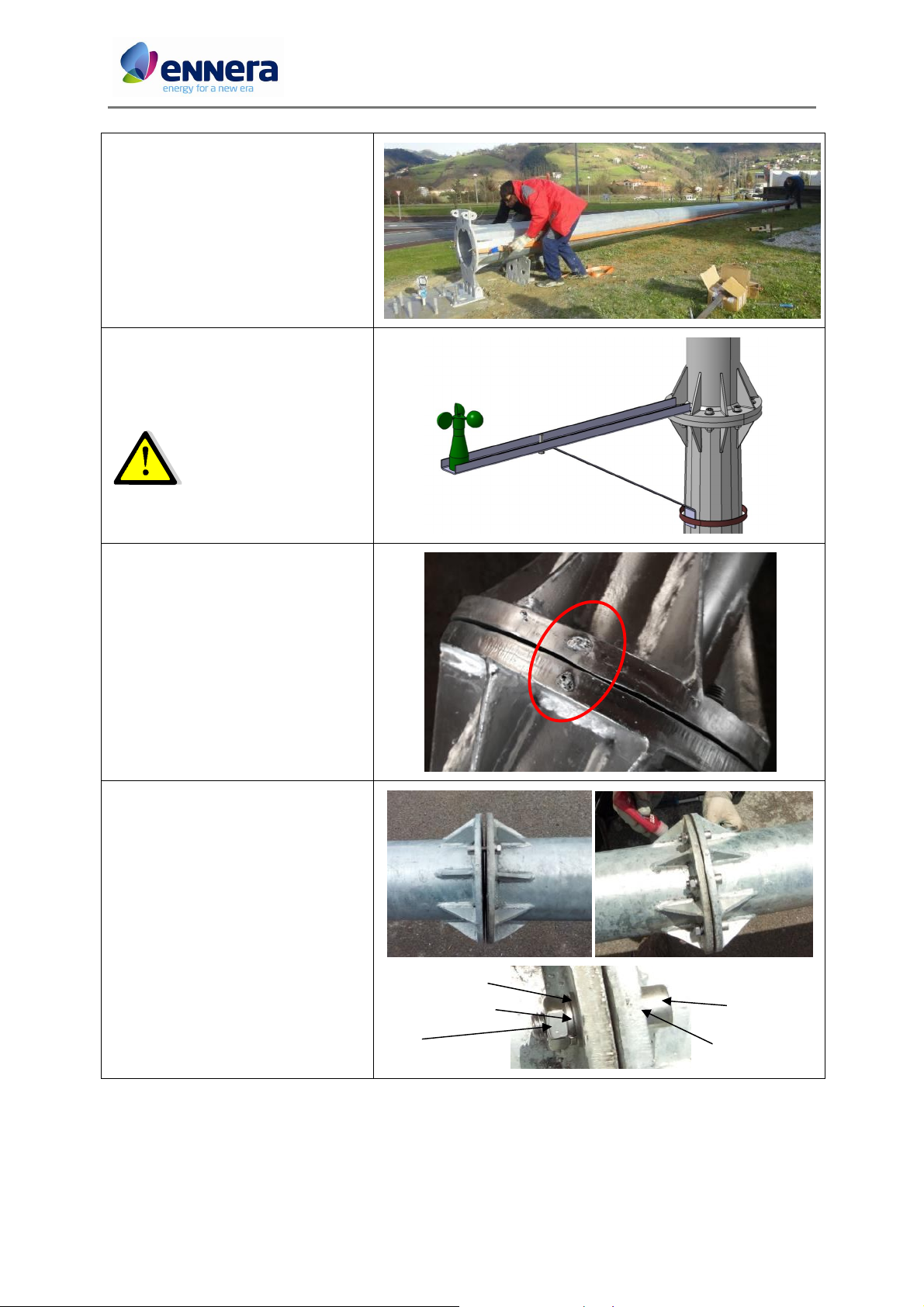
14. Before connecting the fifth section,
make the anemometer assembly.
See section 5.5.
15. To connect the fourth and fifth
sections, align the welding spot in both
sides of the flange.
16. Fix the fourth and fifth sections by
means of a flange:
• Pass the cable guide through the
fifth section.
• Using a screw as a guide, fit
manually the fourth and fifth
sections.
• Fix them with allen M12x50 screws,
washers and nuts.
• Apply Loctite 243 adhesive and tight
them with a torque of 90 Nm.
16 / 66
This document contains confidential information which is property of Ennera Energy and Mobility, S.L. The copy, transmission or use by other people, of the whole document or
part of its contents, is not allowed without written permission from Ennera Energy and Mobility S.L.
Ennera Energy and Mobility, S.L.
Code: I.H4.V10.3003
705mm
Installation and Maintenance Manual Version: 07
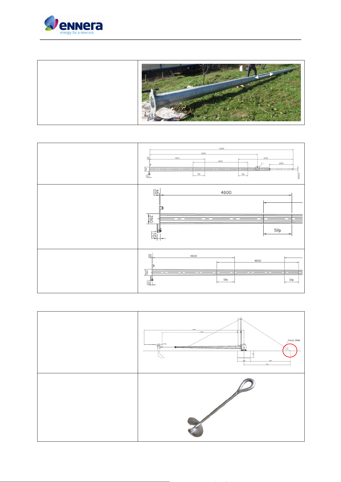
5.3. Ennera design 2-section tower assembly
1. In case the tower is a 2 section
tower (plus the cylindrical pipe), the
interference distance is 705mm.
2. The assembly process is the same
than multi-section tower.
5.4. Ambor design 3 section tower assembly
1. In case the tower is an Ambor design
3 section tower, the assembly process is
the same.
2. The interference (slip) between the
first and second tower sections is 700 ±
240mm.
3. The interference (slip) between the
first and second tower sections is 650 ±
240mm.
5.5. Lifting mechanism
1. The tractel fixing point should be
located 7m away from the foundation
area, aligned with the tower. See Annex
6.
2. The tractel fixing point (EL-1) should
have a disk of 150mm diameter and a
length of 1.5m.
17 / 66
This document contains confidential information which is property of Ennera Energy and Mobility, S.L. The copy, transmission or use by other people, of the whole document or
part of its contents, is not allowed without written permission from Ennera Energy and Mobility S.L.
Ennera Energy and Mobility, S.L.
Code: I.H4.V10.3003
EL-1 EL-2
EL-6
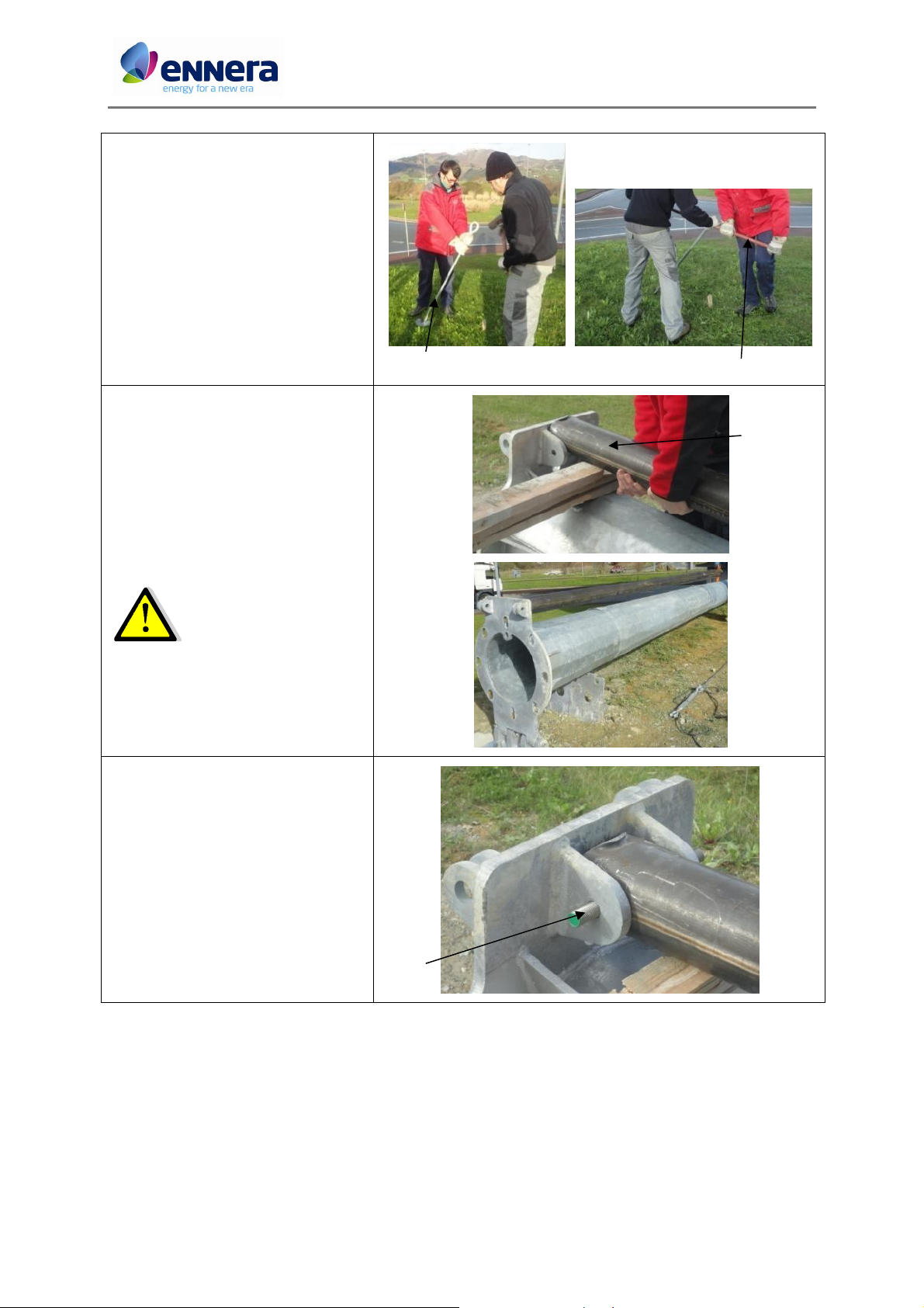
Installation and Maintenance Manual Version: 07
3. Put the ground anchor (EL-1) on the
fixing point with an angle of around 45º
(pointing to the tower) and hit it on the
top with a hammer before start
screwing.
4. With a metal rod (EL-2) inserted in
the ground anchor (EL-1) eye, start
screwing as shown in the figure.
5. After screwing the only visible part
of the ground anchor should be the eye.
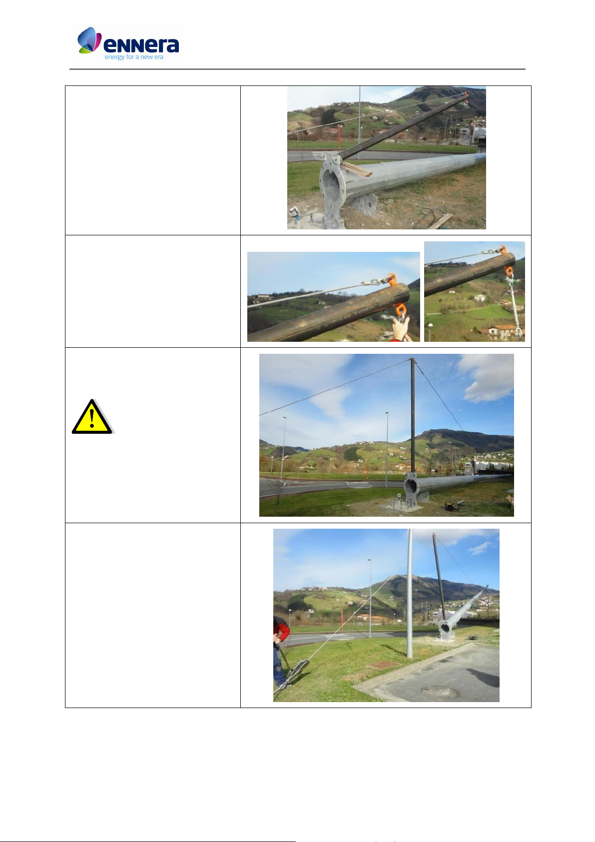
6. Connect the sections of the ginpole
(EL-6) with 4 M10x40 screws.
7. Place the ginpole on the tower as
shown in the figure.
The ginpole is heavy, be
careful transporting it.
8. Fix the ginpole (EL-6) to the tower
base (T1) with a M20x180 screw (EL-8).
EL-8
18 / 66
This document contains confidential information which is property of Ennera Energy and Mobility, S.L. The copy, transmission or use by other people, of the whole document or
part of its contents, is not allowed without written permission from Ennera Energy and Mobility S.L.
Ennera Energy and Mobility, S.L.
Code: I.H4.V10.3003
Installation and Maintenance Manual Version: 07
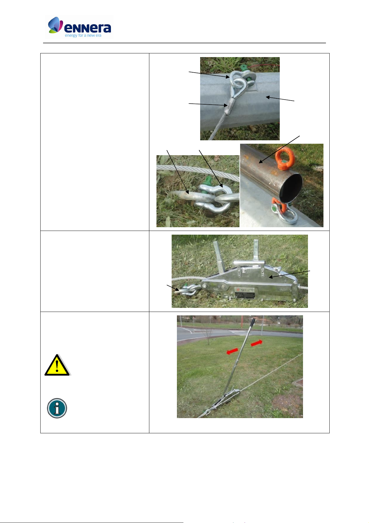
W17
9. Connect the tower shackle (W18) to
the tower’s fourth section (T4) eyebolt.
Connect also the elevation cable (W17).
10. Connect the other shackles (EL-4) to
the ground anchor (EL-1) eye and the
ginpole (EL-6) end.
11. Connect the tractel (EL-3) to the
ground anchor (EL-1) eyebolt.
12. Insert the tractel cable trough it and
connect the other side to the top
eyebolt of the ginpole.
EL-1
EL-1
W16
T4
EL-6
EL-4
EL-3
13. Use the tractel (EL-3) in lift up mode
as shown in the figure to lift the ginpole
(EL-6) up around 1 m from the tower.
Be careful during the lifting
up process. No operators
around the ginpole and
tower while this is lifting.
If anytime the tower needs
to be lifted down during
the process, change the
helping rod of the tractel
and work in the same way
as lifting up.
19 / 66
This document contains confidential information which is property of Ennera Energy and Mobility, S.L. The copy, transmission or use by other people, of the whole document or
part of its contents, is not allowed without written permission from Ennera Energy and Mobility S.L.
Ennera Energy and Mobility, S.L.
Code: I.H4.V10.3003
Installation and Maintenance Manual Version: 07
14. Take the other tip of the elevation
cable (W17) (previously fixed to the
fourth section) and attach it to the
eyebolt of the ginpole with a shackle.
Check alignment of the
ginpole and the tower in
the lifting direction.
15. Once everything is connected,
continue lifting up the ginpole with the
tractel.
16. After the ginpole (EL-6) is in vertical
position, keep working with the tractel
(EL-3) until the tower is in vertical
position.
17. Level the nuts and washers to the
position where the tower is vertical.
18. Once the lift-up test is performed,
lift the tower down to its resting
position.
20 / 66
This document contains confidential information which is property of Ennera Energy and Mobility, S.L. The copy, transmission or use by other people, of the whole document or
part of its contents, is not allowed without written permission from Ennera Energy and Mobility S.L.
Ennera Energy and Mobility, S.L.
 Loading...