

Page 1

ENMET Corporation
PO Box 979
Ann Arbor, Michigan 48106-0979
SPECTRUM-DC-RAL
Compressed Air Line
Carbon Monoxide Monitor
Instrument Manual
80002-035
08-22-97
MCN 192 04-24-98
Page 2

Table of Contents
1.0 DESCRIPTION AND GENERAL INFORMATION
1.1 U
PON RECEIPT
1.1.1 Unpack
1.1.2 Turn On
1.1.3 Check
1.1.4 Expose Sensor
1.1.5 Acknowledge Alarm
1.1.6 Remove Gas
1.1.7 If Non-response
2.0 FEATURES AND OPERATION
2.1 I
NSTALLATION AND OPERATION
2.1.1 Installation
2.1.1.1 Mount Enclosure
2.1.1.2 Air Supply
2.1.1.3 Turn On / Turn Off
2.1.2 Operational Menu
2.1.3 Gas Concentration Display and Alarms
2.1.4 Alarm Acknowledge
2.1.5 Data
2.1.6 Backlight
2.1.7 Low Battery Alarm
2.2 I
NTERFERENCE GASES
3.0 MAINTENANCE
3.1 M
AINTENANCE MENU
3.1.1 Key
3.1.2 Zero
3.1.3 Calibration
3.1.4 Changing the Alarm Level
3.1.5 Setting the Battery Type
3.1.6 Setting a New Key
3.2 C
HANGING COMPONENTS
3.2.1 Sensor Removal and Replacement
3.2.2 Battery Removal and replacement
3.3 ENMET P
4.0 WARRANTY
.......................................................................................................................................................................
.........................................................................................................................................................................
.........................................................................................................................................................................
............................................................................................................................................................................
..............................................................................................................................................................
...................................................................................................................................................
..................................................................................................................................................................
............................................................................................................................................................
.............................................................................................................................................
.......................................................................................................................................
..................................................................................................................................................................
....................................................................................................................................................
................................................................................................................................................................
...................................................................................................................................................
......................................................................................................................................................
.................................................................................................................
...................................................................................................................................................
...............................................................................................................................................................................
......................................................................................................................................................................
......................................................................................................................................................
...........................................................................................................................................................
........................................................................................................................................................................
.........................................................................................................................................................
.................................................................................................................................................................................
................................................................................................................................................................................
................................................................................................................................................................
......................................................................................................................................
..........................................................................................................................................
.....................................................................................................................................................
..................................................................................................................................................
.........................................................................................................................
.........................................................................................................................
ART NUMBERS FOR REPLACEMENT PARTS AND ACCESSORIES
...........................................................................................................................................................................
............................................................................................................
.................................................................
4
4
4
4
4
4
4
4
4
5
5
5
5
6
6
6
6
6
7
7
7
8
9
9
9
9
10
10
11
11
11
11
12
12
13
APPENDIX A
..................................................................................................................................................................................
14
Page 3

List of Illustrations
Figure 1 Carbon Monoxide Monitor Features
•
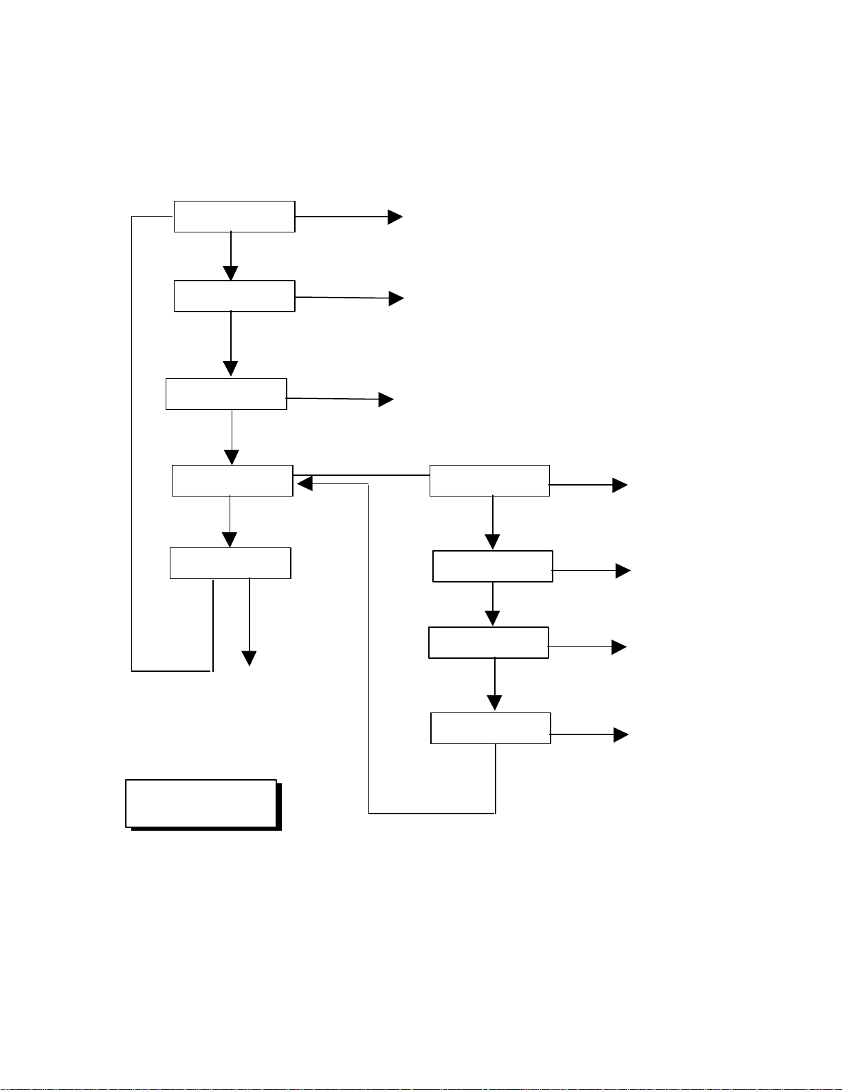
Figure 2 Operation Menu Diagram
•
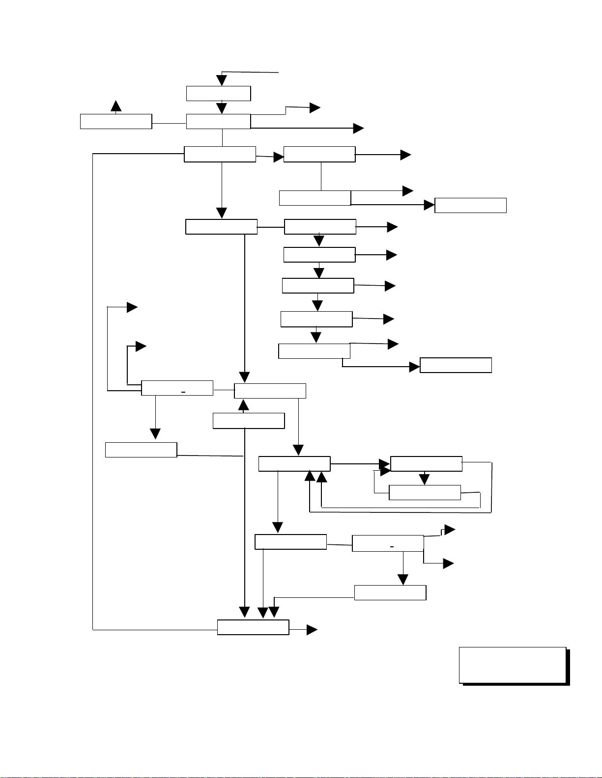
Figure 3 Maintenance Menu Diagram
•
Figure 4 % COHb vs. Time
•
Page 4
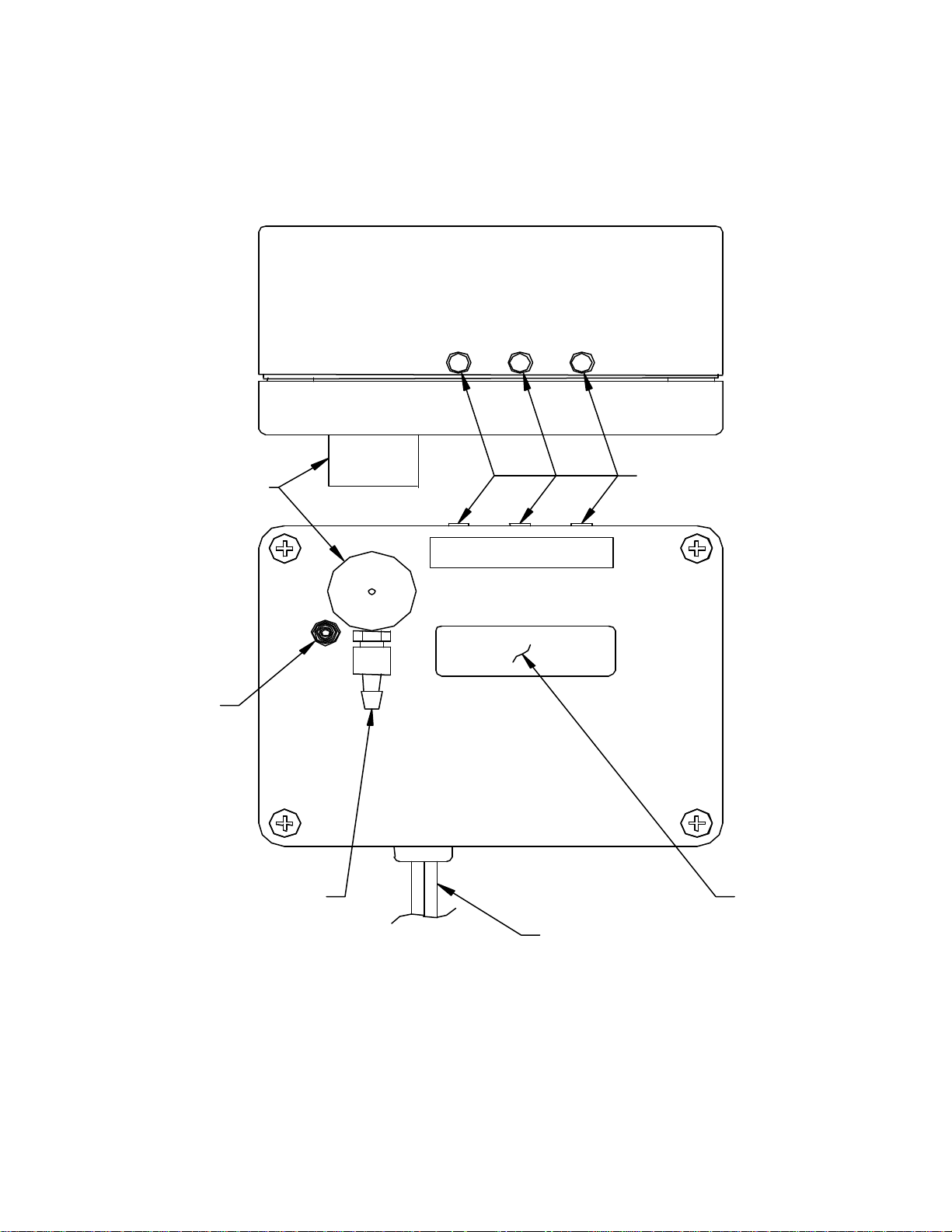
1
PUSHBUTTON
SWITCHES
SAMPLE INPUT
(LUER DISCONNECT)
VISUAL
ALARM
CORD TO
AUDIO ALARM
SENSOR
HOUSING
DISPLAY
POWER-----OPTION-----SELECT
BACKLIGHT
Figure 1: Carbon Monoxide Monitor Features
Page 5
2
O
XX YY °C
No
S
Maintenance
O
Clr DATA
Reset
S
O
go Setup
O
Min=XXXX
No
S
O
O
S
Max=XXXX
See DATA
No
S
O
Alm=XXXX
No
SOO
Batt=OK*
No
*may also be
S
Operational
Display
XXXX
Acknowledge
S
O = Option Switch
Figure 2 Operation Menu Diagram
Alarm
Function
“low” or “LOW”
Function
Function
Menu Key
S = Select Switch
Function
Data
Function
Page 6
3
Key=0000
To Operational
Display
From Operational
Locks underscored digit and moves cursor
OSS
VALID
O
z30:0.0v
O, S, No Function
AIR SET?
O, To Exit
S
S
GAS=XXXX
O, No Function
S
GAS SET?
O, To Exit
S
XXX:Y.Yv
C-FAULT
To Operational Display
VALID
INVALID
O
OOS
SSO
S
run ZERO
O, to Exit
S
z30:0.0v
C-FAULT
To Operational Display
VALID
INVALID
To Operational Display
O
S
Figure 3 Maintenance Menu Diagram
O = Option Switch
O
new=XXXX
O
S
or
KEY=0000
S
O
S
new=XXXX
O or S
O
S
O
S
INVALID
go SETUP
run CAL
Changes digit indicated
by underscore cursor
Locks underscored digit
and moves cursor
Display
Changes digit indicated by underscore cursor
AIR SET?
ALM=0000
set ALM
INVALID
Exit
set KEY
Alk/Lithset BATT
NiCad
Changes digit indicated
by underscore cursor
Locks underscored digit
and moves cursor
S = Select Switch
Page 7

4
1.0 Description and General Information
The SPECTRUM-DC-RAL carbon monoxide monitor is a small battery operated instrument for the
detection of carbon monoxide gas in compressed air lines. An electrochemical cell detects the gas, and
the gas concentration is displayed on an LCD. Audio and visual alarms occur when the gas
concentration exceeds a preset alarm point. At relatively low concentrations of CO, an alarm can be
acknowledged, which results in the temporary cessation of the audio alarm. Operation and maintenance
procedures are managed with two pushbutton switches.
A description of the characteristics and toxic effects of carbon monoxide is given in Appendix A, and
should be reviewed by the user.
1.1 Upon Receipt
1.1.1 Unpack
Unpack the instrument and examine it for shipping damage. If such damage is observed, notify both
ENMET customer service personnel and the commercial carrier involved immediately; save the shipping
box and the packing material.
1.1.2 Turn On
Turn the instrument ON, by pressing and releasing the left pushbutton switch and attach to your
compressed air line system. In uncontaminated air, the display should read 0000 within ten seconds of
turn-on.
1.1.3 Check
Check display operations by pressing the OPTION and SELECT switches as descibed in Figure 2.
The SPECTRUM-DC-RAL instrument is calibrated prior to shipment. However, it is advisable to
apply a known source of carbon monoxide to the instrument to verify the sensor has not been damaged
during shipment.
1.1.4 Expose Sensor
If there is access to a source of CO in compressed air, such as in a calibration kit, expose the sensor to
CO, and observe that the instrument is responsive.
1.1.5 Acknowledge Alarm
If the concentration of CO is greater than 10 ppm, the instrument indicates an alarm condition.
Acknowledge the alarm by pressing and releasing the right hand pushbutton, SELECT; this silences the
audio alarm for four minutes unless the concentration of CO is greater than 50 PPM.
1.1.6 Remove Gas
Remove source of CO. After the display reads zero or close to it, turn the instrument off, by pressing
and holding the left pushbutton switch for 3 seconds.
1.1.7 If Non-response
If the instrument does not operate as described, contact ENMET customer service personnel
immediately.
Page 8

5
2.0 Features and Operation
The features of the SPECTRUM-DC-RAL Carbon Monoxide monitor are shown in Figure 1. These
are:
DISPLAY an LCD upon which either the gas concentration, or prompts for the operational
and maintenance menus, are given.
PUSHBUTTON there are three of these, as follows:
SWITCHES
POWER/
BACKLIGHT the left hand switch
OPTION the middle switch
SELECT the right hand switch
These switches are used to access and utilize the operational and maintenance MENUS.
SENSOR a small cylindrical turret on the display surface; inside which the membrane of
HOUSING the electrochemical sensor is exposed to the compressed air through the air
supply line.
REGULATOR a pressure regulator with a gauge, flowmeter and an adjustable valve, connected
by tubing to the sensor housing. Available on some models per order.
VISUAL ALARM a red LED which is ON whenever the CO concentration is above the alarm
point.
AUDIO ALARM a small horn which is ON whenever the gas concentration is above the alarm
point, until the alarm is acknowledged. There are two variations of audio alarm
location, one with the alarm on a cable, the other with the alarm mounted on the
enclosure.
COVER retained with four screws, and removed to change the sensor and battery.
2.1 Installation and Operation
2.1.1 Installation
2.1.1.1 Mount Enclosure
Mount the enclosure at an appropriate location using the four mounting holes accessible inside the
enclosure. The location should be far enough upstream from the user that the sample air reaches the
monitor before the air reaches the user.
Page 9

6
2.1.1.2 Air Supply
If the model without a regulator is ordered, supply air at approximately 20 PSIG at a flow rate of
approximately 1.0 SCFH. If the regulator is supplied, the male quick disconnect pneumatic connector
on the regulator-flowmeter assembly is a Milton 1000 series. Plumb the associated female connector
into the air line. Connect the regulator-flowmeter and set the pressure at approximately 20 PSIG, and the
flow at 1.0 SCFH.
2.1.1.3 Turn On / Turn Off
To turn on, press and release the POWER/BACKLIGHT pushbutton switch. The display should read
"0000" within ten seconds when the monitor is supplied with uncontaminated air. To turn off, press the
POWER/BACKLIGHT bushbutton switch for three seconds.
2.1.2 Operational Menu
The operational menu diagram is shown in Figure 2. This menu is accessed with the OPTION
pushbutton switch, the middle switch as viewed from the front of the instrument. Successive displays are
achieved by repeatedly pushing the switch, as indicated by "O" in the menu flow diagram. The alarm
acknowledgement function, and displays and functions in the "see DATA" area, are accessed with
SELECT pushbutton, indicated by "S" in the menu diagram.
2.1.3 Gas Concentration Display and Alarms
The LCD furnishes a numerical display of CO concentration from 0000 to 100 ppm; this is the
operational display. If the CO concentration exceeds 100 ppm, the display reads "100+." When the
concentration of CO exceeds the preset alarm point, the audio and visual alarms are activated. The gas
concentration continues to be displayed during alarm. The alarm point is adjustable between 5 and 100
ppm CO by accessing the maintenance menu; the factory setting of the alarm point is 10 ppm CO, the
value recognized by OSHA as the acceptable exposure limit for compressed air lines. A user should
have a justifiable application-based reason for setting the alarm point higher than 10 ppm. When the CO
concentration drops below the alarm point, the audio and visual alarms cease operation. The alarm point
setting can be observed on the display by pushing the OPTION switch twice.
If an alarm concentration is encountered when the display is at a location in the operational menu other
than the operational display, the audio and visual alarms are activated and the alarm cannot be
acknowledged.
If the display is left idle at a location other than the operational display for 45 seconds it automatically
transfers to the operational display.
2.1.4 Alarm Acknowledge
When the instrument is in alarm, and the CO concentration is below 50 ppm, the alarm can be
acknowledged by pressing and releasing the SELECT pushbutton, but only when the instrument is in the
operational display location of the operational menu. The acknowledgement causes the temporary
cessation of the audio alarm; the red LED continues to be ON. The audio alarm is OFF for a period of
four minutes, after which it is reactivated, if the gas concentration is still above the alarm point. The
alarm can again be acknowledged. However, acknowledgement of the alarm at gas concentrations
above 50 ppm does not result in audio alarm cessation, and if the gas concentration rises above 50 ppm
during an alarm condition which has been acknowledged, the audio alarm resumes operation.
Page 10

7
2.1.5 Data
The SPECTRUM-DC-RAL monitor retains the maximum and minimum gas concentration values
encountered since turn-on, or since the data was cleared and reset. There is a one minute delay from
the time the instrument is turned on until when it starts storing the information. To access this press the
OPTION switch three times; "see DATA" is displayed. Press the SELECT switch; the maximum
concentration since turn-on or last reset is displayed. Press the OPTION switch again; the minimum
concentration since turn-on or last reset is displayed. Press the OPTION switch again; "clr DATA" is
displayed. Pushing the SELECT switch clears the data and resets it to the current concentration.
Pushing the OPTION switch once more results in a display of both the countdown to the confidence
beep and the internal temperature of the instrument in degrees centigrade. Push the OPTION switch
three more times to return to the operational display.
2.1.6 Backlight
To backlight the display for observation in a dark area, press and quickly release the POWER /
BACKLIGHT pushbutton. The LCD backlight comes ON for a period of 45 seconds and then turns
OFF automatically. The backlight can be turned off sooner than 45 seconds by pressing the POWER /
BACKLIGHT pushbutton a second time. Use the backlight feature sparingly; it is a relatively high
energy user, and extensive use rapidly depletes the battery.
2.1.7 Low Battery Alarm
The battery status display is accessed by pressing the OPTION pushbutton once. When this display is
"Batt=OK", the battery energy level is sufficient for operation of the instrument. In this condition, the
confidence beep occurs every thirty seconds when the instrument is not in alarm.
When the battery energy level drops below the critically low point, the instrument automatically shuts
off, and cannot be used until the battery is replaced. See paragraph 3.2.2 for batter removal and
replacemamt.
Page 11

8
2.2 Interference Gases
Some gases other than CO cause a sensor response, and thus are termed "interference gases". Known
interference gases are as follows:
Gas Concentration Reading
in ppm in ppm
Hydrogen 1,000 100+
Nitric oxide 100 25
The following levels of gases are known to cause no sensor response:
Gas Concentration
Ammonia 100 ppm
Carbon dioxide 5,000 ppm
Chlorine 5 ppm
Ethylene
Gasoline vapor
Hydrogen cyanide 10 ppm
Hydrogen sulfide
Isopropanol
Methane 10,000 ppm
Nitrogen dioxide
Sulfur dioxide
*
*
*
*
*
*
10 ppm
2 %
saturated
10 ppm
1,025 ppm
10 ppm
*For indicated gases or vapors, prolonged exposure may reduce the efficiency of the sensor filter.
Page 12

9
3.0 Maintenance
3.1 Maintenance Menu
From the gas operational display, push the OPTION button four times; "go SETUP" is displayed. This
is the entrance to the maintenance menu. The maintenance menu diagram is shown in Figure 3.
3.1.1 Key
Entrance to the maintenance menu is guarded with a four digit numerical key. The factory default setting
of the key is 1270. When the valid numerical key is inserted, the user is allowed to enter the
maintenance menu.
When in the "go SETUP" location, press the SELECT pushbutton; "Key=0000" is displayed. The
underscore cursor is under the left hand digit. To insert the key, press the OPTION pushbutton to
index the left hand digit, and choose the correct digit; then press the SELECT pushbutton, which locks
in the chosen left hand digit and moves the underscore cursor one space to the right. Continue this
process until the four digit key is complete. When the valid key is inserted in this manner, the display is
transferred to the "run ZERO" portion of the maintenance menu. When an invalid key is inserted,
"INVALID" is briefly displayed, and the instrument returns to the operations menu.
The process by which means a different key is set is given in paragraph 3.1.6, below.
3.1.2 Zero
A valid key entry sets the instrument at the "run ZERO" location, of the maintenance menu, which
enables the setting of the zero gas concentration point. This is desirable if the zero reference of the gas
sensor has drifted over a period of time, indicated by a persistent gas concentration reading in a clean
environment. Note that the calibration sequence given below also includes setting the zero point. If a
full calibration is required, instead of setting just the zero point, push the OPTION button once; "run
CAL" is displayed. See paragraph 3.1.3, below.
To set the zero point without performing full calibration, from the "run ZERO" location press the
SELECT button; "AIR SET?" is displayed. Be certain that the instrument is supplied with clean air,
uncontaminated by carbon monoxide. If uncertain of the environment, use pure compressed air from a
pressurized cylinder, and flow it over the sensor at a flow rate of 1 SCFH.
With the instrument in zero air, press the SELECT button again. "ZERO=30" is displayed; this is a
counter that counts down in seconds from 30 to 0. The validity of the new zero setting is then
examined; if it is reasonable, the display is transferred to the concentration numerical display in the
operations menu.
If the new zero setting is not between reasonable parameters, "C-FAULT" is displayed. Turn the
instrument OFF, the ON again. This re-boots the system with the most recent valid zero setting.
Page 13

10
3.1.3 Calibration
NOTE: Calibration should be performed at normal room temperature (20-25°C) for optimal
performance. If the instrument is exposed to temperature extremes just prior to calibration, it should be
allowed to stabilize to room temperature. The internal temperature of the instrument can be verified by
cycling through the "see DATA" menu.
In order to calibrate the instrument, it is first zeroed as described above. Then the sensor is presented
with a known concentration of the target gas, in air or an inert gas such as nitrogen, called the "span
gas". After an appropriate interval, which is timed, the new span setting is examined for validity.
A valid key entry sets the instrument at the "run ZERO" location of the maintenance menu. Press the
OPTION pushbutton once to access the "run CAL" display, then press the SELECT pushbutton; "AIR
SET" is displayed. Zero the instrument as described in paragraph 3.1.2 above. When the zero timer is
complete, the display indicates "SPAN=XXX", where the numbers indicate the correct span gas
concentration for the instrument. The span gas value for this instrument is 20 ppm CO.
Assure that the correct span gas is available, connect the calibration adapter to the cylinder, then press
the SELECT button; "GAS SET" is displayed. Unplug the regulator-flowmeter assembly from the
airline, connect it to the calibration adapter and set the flow at 1.0 SCFH. Then press the SELECT
button; "XXX:0.Yv" is displayed. The XXX is a counter which counts down in seconds to zero from
120 to provide the proper time interval for calibration. The 0.Yv indicates a sensor signal which is used
during the sensor replacement procedure. When the timer reaches zero, the new calibration and zero
gas settings are examined for validity. If the values are reasonable, the display is transferred to the gas
concentration numerical display in the operations menu. Return the regulator-flowmeter assembly to the
airline.
If the new zero and calibration settings are not reasonable, "C-FAULT" is displayed. Turn the
instrument OFF, then ON again. This re-boots the system with the most recent valid zero and
calibration settings.
3.1.4 Changing the Alarm Level
A valid key entry sets the instrument at the "run ZERO" location of the maintenance menu. Press the
OPTION push button twice to access the "set ALM" display, then press the SELECT button;
ALM=0000" is displayed. This is called the alarm update window, and the value displayed is the
present alarm setpoint. The underscore cursor is under the far left digit. Press the OPTION button to
index the underscored digit; press the SELECT button to index the underscore cursor one position to
the right. When the desired new alarm point is set, press either the OPTION or SELECT button to
return to the alarm update window. If the new alarm setting is valid, "set ALM" is again displayed.
Press the OPTION button four times to return to the operations menu.
Page 14

11
For the safety of the user, there is an upper limit past which the alarm setting is invalid, and the
instrument does not accept it. If an invalid alarm setting is attempted, after the numerical value is
inserted in the "ALM=0000" window, pressing the OPTION or SELECT button results in a momentary
display of "INVALID" after which the display returns to the alarm update window. Exiting the alarm
update window at this point results in an alarm point setting unchanged from the value present when the
procedure was begun.
For the SPECTRUM-DC-RAL, the factory default alarm setpoint is 10 ppm, and the upper alarm limit
is 50 ppm.
3.1.5 Setting the Battery Type
A valid key entry sets the instrument at the "run ZERO" location of the maintenance menu. Press the
OPTION pushbutton three times to access the "set BATT" display, then press the SELECT
pushbutton; "Alk/Lith" is displayed. Press the OPTION pushbutton to cycle the display among the two
types of batteries which are valid, "Alk/Lith" and "NiCad". Choose the battery type that is being used
to power the instrument by pressing the SELECT pushbutton; doing so returns the display to "set
BATT" location. Push the OPTION pushbutton three times to return to the maintenance menu. The
NiCad display is equal to the Ni/MH battery.
If the "set batt" selection is not identical with the battery being used, incorrect low battery indications
are furnished.
3.1.6 Setting a New Key
A valid key entry sets the instrument at the "run ZERO" location of the maintenance menu. Press the
OPTION button four times to access the "set KEY" display. Press the SELECT pushbutton once;
"KEY=0000 is displayed. A new key can be set by indexing the underscored number with the
OPTION button and indexing the underscore cursor with the SELECT button. Four digit key numbers
should be selected carefully and recorded. Without the correct key, the maintenance menu cannot be
accessed. If a four digit key number is lost, call ENMET customer service personnel.
3.2 Changing Components
Changing the sensor requires that the front of the instrument be removed; remove the four phillips head
cover retaining screws, and then the cover.
3.2.1 Sensor Removal and Replacement
A sensor must be replaced when it no longer responds adequately to the target gas. This is indicated by
a low gas concentration reading when exposed to a known concentration of the target gas, and the
inability to calibrate the instrument, with a "C-FAULT" display after calibration. The expected sensor
lifetime in normal environments is one to two years.
Remove the front cover of the instrument enclosure. Unplug the sensor from the circuit board, and plug
in the new sensor in its place. Allow the sensor to stabilize in the instrument with the power on for one
hour before recalibrating.
Page 15

12
The initial calibration of a new sensor must be performed with the front cover of the enclosure removed.
A calibration cup is provided with the calibration kit. Follow the procedure for calibrating the
instrument as outlined in Section 3.1.3 of this manual with the following modification.
During the application of the span gas, the counter counts down from 120. When the counter
gets down to 30, adjust the potentiometer next to the display module on the instrument PC
board, so that the display to the right of the counter reads 0.65v. This is a one-time
adjustment to align the sensor output with the instrument electronics. It should only be
performed upon sensor replacement. All future calibrations should follow the procedure in
Section 3.1.3.
Replace the front cover on the instrument enclosure. Calibrate the instrument according to the
procedure in paragraph 3.1.3.
3.2.2 Battery Removal and replacement
Remove the front of the instrument. The battery is in a clip in the lower right of the enclosure. Remove
it, unclip the battery connector, replace with a 9 volt alkaline battery. Push the new battery into the clip
and replace the cover.
Two types of batteries are available for use with the SPECTRUM-DC-RAL: alkaline and rechargeable
Ni/MH. They have different end-of-life discharge characteristics. Either replace a battery with the
same type, or go to the "set BATT" portion of the maintenance menu, and select the new type being
used. See paragraph 3.1.5 to set battery type.
If the "set batt" selection is not identical with the battery being used, incorrect low battery indications
are furnished.
The rechargeable Ni/MH battery is of a common type which can be charged by a charger available at
any electronic store.
3.3 ENMET Part Numbers for Replacement Parts and Accessories
Description Part Number
Calibration Kit 03412-001
Calibration Gas, 20 ppm CO 03219-020
Zero Gas, 20.9 % Oxygen 03296-209
Replacement CO Sensor, for S/N 41-2106 and below 67020-1200
Replacement CO Sensor, for S/N 41-2150 and above 67016-1204
Display Assembly 62022-007
PC Board Assembly 05215-002
Battery, alkaline 67012-001
Battery, Ni/MH 67011-003
Page 16

13
4.0 Warranty
ENMET warrants new instruments to be free from defects in workmanship and material under normal
use for a period of one year from date of shipment from ENMET. The warranty covers both parts and
labor excluding instrument calibration and expendable parts such as calibration gas, filters, batteries, etc.
Equipment believed to be defective should be returned to ENMET within the warranty period
(transportation prepaid) for inspection. If the evaluation by ENMET confirms that the product is
defective, it will be repaired or replaced at no charge, within the stated limitations, and returned prepaid
to any location in the United States by the most economical means, e.g. Surface UPS/RPS. If an
expedient means of transportation is requested during the warranty period, the customer is responsible
for the difference between the most economical means and the expedient mode. ENMET shall not be
liable for any loss or damage caused by the improper use of the product. The purchaser indemnifies
and saves harmless the company with respect to any loss or damages that may arise through the use by
the purchaser or others of this equipment.
This warranty is expressly given in lieu of all other warranties, either expressed or implied, including that
of merchantability, and all other obligations or liabilities of ENMET which may arise in connection with
this equipment. ENMET neither assumes nor authorizes any representative or other person to assume
for it any obligation or liability other than that which is set forth herein.
NOTE: When returning an instrument to the factory for service:
-- Be sure to include paperwork.
-- A purchase order, return address and telephone number will
assist in the expedient repair and return of your unit.
-- Include any specific instructions.
-- For warranty service, include date of purchase
-- If you require an estimate, please notify ENMET.
Page 17

14
Appendix A
Figure 4 % COHb vs Time
The Characteristics and Effects of Carbon Monoxide
Carbon monoxide is a colorless odorless toxic gas generated by incomplete combustion of a hydrocarbon fuel
in air. It may be present where internal combustion engines, furnaces, boilers, and other combustion devices
are present. It is toxic when inhaled because of its great affinity to hemoglobin, the oxygen carriers in the red
cells of the blood. CO replaces the oxygen normally carried by the hemoglobin, and thus inhibits the delivery
of oxygen throughout the body; the victim suffers from oxygen deficiency, and may die from asphyxiation.
The symptoms and degree of danger resulting from exposure to CO depend upon the concentration of the gas
and the length of exposure; this is shown in Figure 4. The ENMET SPECTRUM-DC-RAL carbon monoxide
monitor is employed to warn the user of the presence of CO, and to facilitate the assessment of the degree of
danger that he or she is exposed to.
Based upon knowledge of the effects of CO, the Occupational Safety and Health Authority (OSHA) has set
limits on exposure to CO in the workplace. For ambient air conditions, these are 35 ppm (parts CO per
million parts air) as an time weighted average for an eight hour day, and a maximum exposure of 200 ppm.
For compressed air line applications, 10 ppm is the maximum acceptable limit. The SPECTRUM-DC-RAL
monitor is shipped with the adjustable alarm set at 10 ppm; this alarm cannot be adjusted above 50 ppm.
The curves below are for percent carboxalhemoglobin with 50% being the top curve, 5% the bottom.
%COHb is a measure of the amount of hemoglobin occupied by CO rather than oxygen. CO effects upon
children, adults engaging in physical activity, and smokers, are more pronounced.
 Loading...