

Page 1

ENMET Corporation
PO Box 979
Ann Arbor, MI 48106-0979
Sensor Transmitter
SDS – 97D
Manual
Manual Part Number
80003-034
MCN-443, 01/21/11
Page 2

Table of Contents
1.0 I
NTRODUCTION
1.1 Unpack ........................................................................................................................................................1
1.2 Check Order ................................................................................................................................................1
1.3 Serial Numbers ............................................................................................................................................1
2.0 S
ENSOR / TRANSMITTER
2.1 Features .......................................................................................................................................................2
2.2 Installation ...................................................................................................................................................3
2.2.1 Sensor/Transmitter without ISB ........................................................................................................3
2.2.2 Sensor/Transmitter with ISB .............................................................................................................4
2.3 Calibration ...................................................................................................................................................6
2.3.1 Automatic Zeroing .............................................................................................................................7
2.3.2 Automatic Calibration .......................................................................................................................7
3.0 P
ROGRAMMER
4.0 S
ENSOR REPLACEMENT
5.0 W
ARRANTY
..................................................................................................................................... 1
....................................................................................................................... 2
...................................................................................................................................... 8
........................................................................................................................ 8
.......................................................................................................................................... 9
List of Illustrations
F
IGURE A:
T
ABLE 1: WIRING WITHOUT
F
IGURE B: DIRECT WIRING TO CONTROL
T
ABLE 2: WIRING AT
F
IGURE C: WIRING TO
T
ABLE 3: WIRING AT
F
IGURE D: WIRING TO
T
ABLE 4: STIPULATED CALIBRATION GASES FOR DIGITAL SENSOR/TRANSMITTERS
F
IGURE E: CALIBRATION WITH GAS
F
IGURE F:
SDS – 97D S
S/T 4
ISB 4
ISB 5
ISB
SDS – 97D S
ENSOR/TRANSMITTER
2
ISB 3
3
IN CONTROL
5
7
ENSOR/TRANSMITTER WITH TURRET AND SENSOR REMOVED
6
8
Page 3

SDS – 97D Sensor / Transmitter ENMET Corporation
1.0 Introduction
♦ Each sensor/transmitter consists of an electrochemical gas detection sensor combined with digital circuitry
to detect a particular toxic gas, or to detect oxygen concentrations.
♦ Each sensor/ transmitter is equipped with an LCD display to indicate the level of concentration of gas or oxygen
in the vicinity of the sensor/transmitter.
♦ Each sensor/transmitter is equipped with a pushbutton switch for easy automatic zeroing and calibration
with bottled gas.
♦ Each sensor/transmitter is in a painted aluminum enclosure provided with gaskets designed to furnish NEMA-4
protection.
♦ Sensor/transmitters are three wire devices, with two of the wires forming a 4-20 mA loop.
♦ Some sensor/transmitters are equipped with a communications circuit and connector which, when used in
conjunction with a programmer, facilitates the changing of a sensor without recalibration.
N
OTE
: All specifications stated in this manual may change without notice.
1.1 Unpack
Unpack the SDS – 97D and examine it for shipping damage. If such damage is observed, notify both ENMET customer
service personnel and the commercial carrier involved immediately.
Regarding Damaged Shipments
N
OTE
: It is your responsibility to follow these instructions. If they are not followed, the carrier will not honor
any claims for damage.
This shipment was carefully inspected, verified and properly packaged at our company and delivered to the carrier in good
condition.
When it was picked up by the carrier at ENMET, it legally became your company’s property.
If your shipment arrives damaged:
• Keep the items, packing material, and carton “As Is.” Within 5 days of receipt, notify the carrier’s local office and
request immediate inspection of the carton and the contents.
• After the inspection and after you have received written acknowledgment of the damage from the carrier, contact
ENMET Customer Service for return authorization and further instructions. Have your Purchase Order and Sales Order
numbers available.
ENMET either repairs or replaces damaged equipment and invoices the carrier to the extent of the liability coverage, usually
$100.00. Repair or replacement charges above that value are your company’s responsibility.
The shipping company may offer optional insurance coverage. ENMET only insures shipments with the shipping company
when asked to do so in writing by our customer. If you need your shipments insured, please forward a written request to
ENMET Customer Service.
Regarding Shortages
If there are any shortages or questions regarding this shipment, please notify ENMET Customer Service within 5 days of
receipt at the following address:
ENMET Corporation
680 Fairfield Court
Ann Arbor, MI 48108
734-761-1270 734-761-3220 Fax
1.2 Check Order
Check, the contents of the shipment against the purchase order. Verify that the SDS – 97D is received as ordered. Each SDS
– 97D is labeled with its target gas.] If there are accessories on the order, ascertain that they are present. Check the contents of
calibration kits. Notify ENMET customer service personnel of any discrepancy immediately.
1.3 Serial Numbers
Each SDS – 97D is serialized. These numbers are on tags on the equipment and are on record in an ENMET database.
1
Page 4
SDS – 97D Sensor / Transmitter ENMET Corporation
Calibration & Zeroing
Communications
Mounting Hole
Mounting Hole
Calibration & Zeroing
Communications
2.0 Sensor / Transmitter
2.1 Features
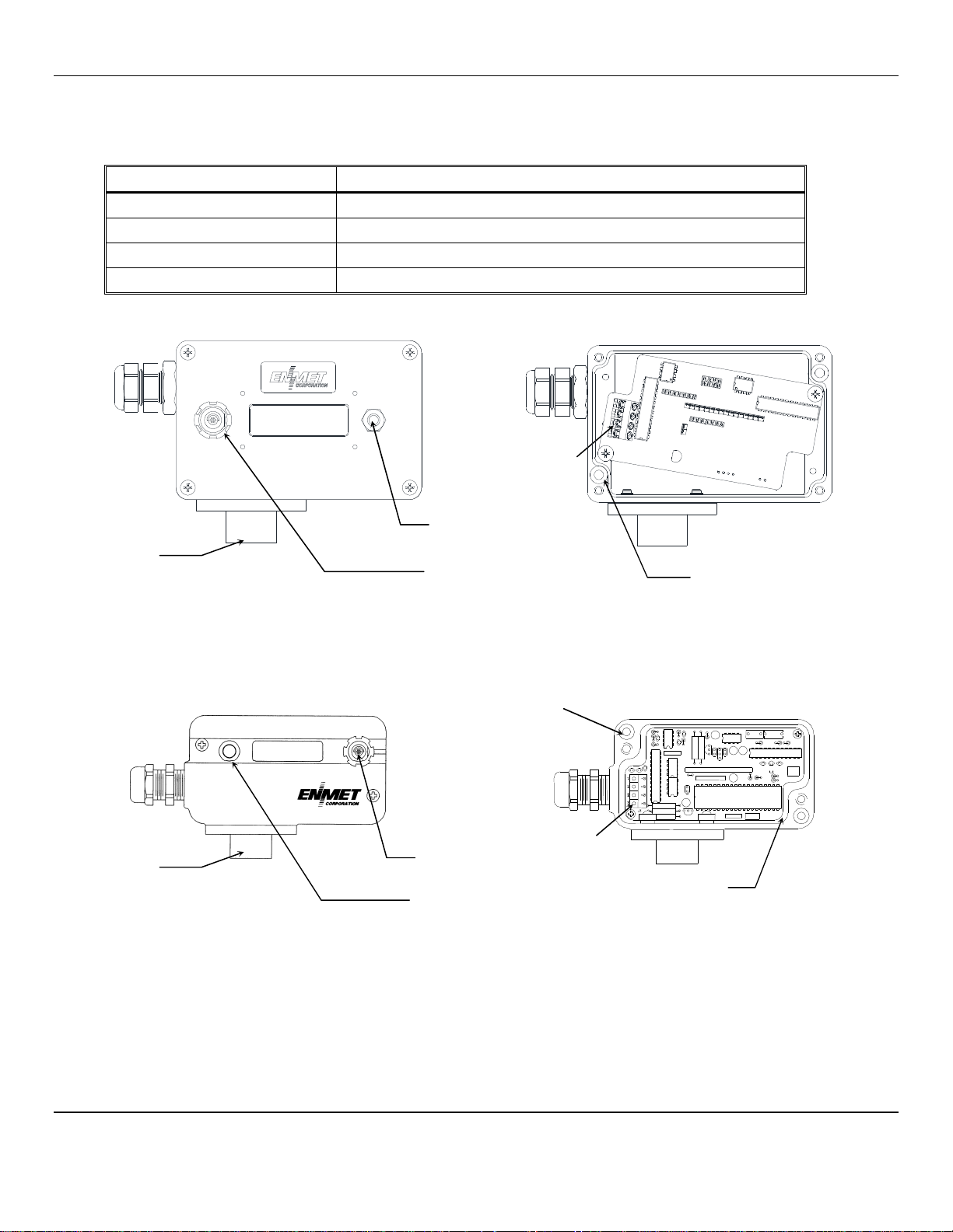
See figure A for location of features for both styles of enclosure.
Feature Function
Display
Pushbutton Switch
Communications Connector
Sensor
LCD, indicated the level of gas or oxygen detected by sensor
For automatic zeroing and calibration, see section 2.3
For programming with programmer, see section 3
For sensing gas or oxygen, see table 4 for sensor types
J3
Sensor
Sensor
Pushbutton Switch
Connector
2 places
Exterior View Cover Removed
2 places
J3
Sensor
Connector
Gasket
Pushbutton Switch
Figure A: SDS – 97D Sensor/Transmitter
2
Page 5

SDS – 97D Sensor / Transmitter ENMET Corporation
1 – V+
C
SDS –
97D
2.2 Installation
• The interior of a sensor/transmitter with the cover removed is shown in the accompanying Figure A, for reference during
these operations.
• Remove the cover of the sensor/transmitter by removing the two black cover screws.
• Mount the sensor/transmitter to an appropriate stable vertical surface with the sensor facing downward.
C
AUTION
: Since the sensor/transmitter detects gas only at the sensor location, pay attention to the possible sources of gas,
the density of the gas, locations where the gas may be confined and locations where the gas may damage or injure property or
personnel, when choosing locations of sensor/transmitters.
• Mount the sensor/transmitter using the two mounting holes in the corners of the enclosure. For maximum RFI protection
the enclosure should be grounded to earth ground, either by means of the mounting screws, a conductive conduit, or a wire
connected to earth ground.
• The interface terminal strip J3 is located at the left edge of the internal circuit board. Wires enter through the port in the left
wall of the enclosure, that is supplied with a watertight strain relief. Wiring may be with good quality three conductor
shielded cable or with three insulated wires in metallic conduit. When the watertight strain relief is removed, the hole at the
entry point is threaded 3/8 NPT female; use appropriate watertight conduit fittings.
2.2.1 Sensor/Transmitter without ISB
Wiring without Intrinsic Safety Barriers to the following points shown in Table 1 and Figure B:
Table 1: Wiring Without ISB
Position Function
J3-1 V+, the power supply
J3-2 signal, the positive side of the loop
J3-3 ground, the negative side of the loop
J3-4 shield, earth ground
Maximum resistance of the power supply wire is 300 ohms when 24 V
resistance of the signal loop is 300 ohms. A very small current flows in the negative signal wire. To avoid current loops in the
earth ground circuit, connect one end, only, of the shield or conduit to earth ground.
Connect the other ends of the three wires to the appropriate terminals of the control or computer used to monitor the 4-20 mA
sensor/transmitter signal, and the power supply. A power supply must be capable of providing 10 to 24 V
sensor/transmitter. Maximum current draw is 45 mA.
Allow the sensor/transmitter to stabilize for 3 to 24 hours.
DC
is supplied at the control, and the maximum load
DC
at the
ONTROL
See control
manual
Sensor / Transmitter
J3
2 – Signal
3 – Ground
4 – Shield
Figure B: Direct Wiring to C
3
V+
Signal
Ground
ONTROL
Page 6

SDS – 97D Sensor / Transmitter ENMET Corporation
SDS –
97D
– +
2.2.2 Sensor/Transmitter with ISB
Installation with a recommended Intrinsic Safety Barrier properly connected and grounded renders the sensor/transmitter
nonincendive as defined by the National Electrical Code. An MTL 787S+ barrier is recommended connected as shown in
Figure C. Connections at the sensor/transmitter are shown in Table 2 as follows:
Table 2: Wiring at S/T
Position Function
J3-1 V+, the power supply
J3-2 signal, the positive side of the loop
J3-3 ground, the negative side of the loop
J3-4 shield, only if the sensor/transmitter enclosure is not grounded
24 VDC
Regulated
Power
Supply
ISB, MTL 787S+
1
2
Earth ground
Readout
4-20mA
Sensor / Transmitter
J3
1 V+
2 Signal
3 Ground
4 Shield, if necessary
Hazardous Area
3
4
Safe Area
Figure C: Wiring to ISB
When the sensor/transmitter is mounted and wired, assure that the cover gasket is in place, replace the cover, and secure it with
the two cover screws.
Allow the sensor/transmitter to stabilize for 3 to 24 hours.
4
Page 7

SDS – 97D Sensor / Transmitter ENMET Corporation
C
SDS –
97D
24 VDC
Supply
If the sensor/transmitter enclosure is grounded, connect the shield at the control.
The terminals on the barrier are clearly numbered, and a schematic of the barrier is on a label on the barrier housing. At the
barrier, the connections are as shown in Table 3 and Figure D:
Table 3: Wiring at ISB
Position Function
1 V+, power supply, safe side
2 signal, the positive side of the loop, safe side
3 V+, power supply, hazardous side
4 signal, the positive side of the loop, hazardous side
The negative side of the loop (from J3-3 at the sensor/transmitter), the negative side of the readout device, and the negative side
of the 24 V
been temporarily declassified, it is good practice to connect the negative side of the loop to earth ground first, and, if
disconnecting a sensor/transmitter, disconnect the same wire last. The two ground points on the barrier must be securely
connected to earth ground with a connection that cannot be interrupted by separating a connector or pulling the plug of a line
cord.
A regulated 24 V
blows the fuses in the barrier, and the barrier must be replaced.
The maximum resistance of the power supply wire is 125 ohms when 24 V
combined resistance of the positive loop wire and the readout device is 340 ohms. Very little current flows in the negative loop
wire.
DC
power supply are all connected to earth ground at the barrier. When working in a hazardous area, even if it has
DC
power supply must be used to provide the V+ power to the sensor/transmitter. Supplying over 26 V
DC
is supplied through the barrier. The maximum
ONTROL
See control manual
DC
Regulated
Power
Signal
Ground
– +
ISB, MTL 787S+
Sensor / Transmitter
J3
1 V+
2 Signal
3 Ground
4 Shield, if necessary
Hazardous Area
3
4
Safe Area
Figure D: Wiring to ISB in C
1
2
Earth ground
ONTROL
When the sensor/transmitter is mounted and wired, assure that the cover gasket is in place, replace the cover, and secure it with
the two cover screws.
Allow the sensor/transmitter to stabilize for 3 to 24 hours.
5
Page 8

SDS – 97D Sensor / Transmitter ENMET Corporation
2.3 Calibration
C
AUTION
Calibration is the process of aligning the pre set instrument electronics to the installed sensors, making the instrument read
accurately. It consists of a zero reading which tells the instrument what it should read in uncontaminated (clean) air, and a span
reading that tells the instrument what it should read in the presence of its target gas. Calibration, including the zero and span
adjustments should be performed on a quarterly basis.
Sensor/transmitters are supplied with a pushbutton switch, located on the left side of the front surface. Never push this switch
unless zero or span gas is being applied to the sensor (see caution). This switch facilitates automatic zeroing and automatic
calibration with appropriate gas. The parameters described; stipulated calibration gas, response to calibration gas and the
ENMET part number for a cylinder of calibration gas are given for various sensor types in Table 4.
:
Sensor/transmitters must be calibrated with the stipulated calibration gas. Although safeguards are provided, it is
possible to miscalibrate a sensor/transmitter by using the incorrect gas.
Table 4: Stipulated Calibration Gases for Digital Sensor/Transmitters
S/T for Gas Calibration Gas Response Cal Gas P/N
Ammonia 50ppm NH3 50 ppm 03318-050
Arsine 0.5 ppm PH3 0.5 ppm 03305-005
Boron Trichloride 10 ppm HCL 10 ppm 03302-010
Carbon Monoxide 100 ppm CO 100 ppm 03219-100
Chlorine 5 ppm CL2 5 ppm 03331-005
Chlorine Dioxide Consult ENMET
Chlorine Trifluoride Consult ENMET
Dichlorosilane 10 ppm HCL 3 ppm 03302-010
Ethylene Oxide 5 ppm ETO 5 ppm 03332-005
Fluorine Consult ENMET
Hydrogen 800 ppm H2 800 ppm 03227-800
Hydrogen Bromide 5 ppm HCL 25 ppm 03302-005
Hydrogen Chloride 10 ppm HCL 10 ppm 03302-010
Hydrogen Cyanide 10 ppm HCN 10 ppm 03303-010
Hydrogen Fluoride 5 ppm CL2 3 ppm 03331-005
Hydrogen Sulfide 20 ppm H2S 20 ppm 03314-020
Nitrogen Dioxide 5 ppm NO2 5 ppm 03333-005
Nitric Oxide 25 ppm NO 25 ppm 03334-025
Oxygen *see note 2 20.9 % O2 20.9 % 03296-209
Ozone 0.3 ppm O3 0.3 ppm Use Ozone generator
Phosgene Consult ENMET
Phosphine 0.5 ppm PH3 0.5 ppm 03205-005
Silane 5 ppm SiH4 5 ppm 03306-005
Silicon Tetrachloride 5 ppm HCL 25 ppm 03302-005
Sulfur Dioxide 10 ppm SO2 10 ppm 03315-010
N
OTE
N
1: All specifications stated in this manual may change without notice.
OTE
2:
* Oxygen S/T with a 0 – 30% range are zero set at the factory. 20.9% by volume O2/78.1% by volume N2 is the
calibration gas. If zeroing of an Oxygen S/T should be needed 100% by volume N2 (0% by volume O2) is the zero
gas.
Toxic S/T 20.9% by volume/78.1% by volume N2 may be used for (clean air) zero gas, see section 2.3.1 automatic
zeroing.
6
Page 9

SDS – 97D Sensor / Transmitter ENMET Corporation
Calibration & Zeroing
Calibration
Calibration
Flow Control
2.3.1 Automatic Zeroing
O
XYGEN
calibration.
T
OXIC
must be exposed to a source of fresh, clean air to perform an automatic zeroing procedure. Kits are available from ENMET
Corporation that includes a cylinder of 20.9% oxygen, free of contaminants. The recommended flow rate of air from a cylinder
is 0.5 liters per minute.
Expose the sensor to fresh clean air for at least 30 seconds. Press and release the Calibration & Zeroing Pushbutton Switch.
After the switch is released, if the signal from the sensor is within the established Zero (clean) range, the sensor/transmitter
display is forced to zero. If the sensor reading is too high or too low, zeroing will not take place.
If the sensor/transmitter does not read zero and continues to read more than several display units above zero, expose the sensor to
clean air from a cylinder of 20.9% oxygen for 2 minutes. After 2 minutes, press and release the Calibration & Zeroing
Pushbutton Switch again. If the display still does not zero, the sensor may need to be replaced.
S/T: Oxygen S/T, 0 – 30% by volume, do not require the automatic zeroing step, proceed to section 2.3.2 automatic
S/T: If the air around the sensor/transmitter contains significant levels of the target gas or interference gases, the sensor
N
OTE
: Under certain conditions, the display may be off 1 display unit.
2.3.2 Automatic Calibration
ENMET Corporation makes available a calibration kit that contains the stipulated calibration gas and a calibration adapter.
With reactive gases it is imperative that the proper regulator, tubing and calibration cover be used. Failure to do so, may cause
inaccurate and/or failed calibrations. Contact your local distributor or ENMET for more information.
See Table 4 for calibration gas values and replacement cylinder part numbers.
Pushbutton Switch
Cup
Adapter
Gas Cylinder
Valve
Figure E: Calibration with Gas
Screw the regulator valve of the calibration adapter onto the calibration gas cylinder, and open the flow control valve. Put the
cup over the sensor. See Figure E. After 1-3 minutes, when the display stops changing, press the calibration switch.
If the sensor output is within the calibration range, the display changes to the value of the contents of the calibration gas.
Example if calibrating with 50
N
OTE
: Under certain conditions, the display may be off ± 1 display unit, Hydrogen may be off ± 20 ppm.
W
ARNING
:
If at this point the display does not change, calibration has not been accomplished. Check the following:
♦ Be sure that the proper calibration adapter is being used. Reactive gases can be absorbed by standard tubing. Special non-
reactive tubing should be used for reactive gases. ENMET calibration kits are supplied with appropriate tubing for the gas
in the kit.
♦ Be sure that the gas is not outdated. The shelf life or manufacture date is on the gas cylinder label.
♦ If sufficient fresh calibration gas is being used, try the calibration again. If the same result is obtained, the most probable
cause is a sensor with low output. Such a sensor is nearing the end of its useful life. Install a new sensor per Section 4.0,
and recalibrate.
PPM
CO, the display changes to “0050”.
7
Page 10

SDS – 97D Sensor / Transmitter ENMET Corporation
3.0 Programmer
If the SDS-97D sensor/transmitter is supplied with the communication port option, it has the capability to interface with a
remote programming device. The SDS-97D Programmer is supplied with its own manual detailing its operation.
4.0 Sensor Replacement
Sensors need to be replaced when they no longer respond properly to calibration gas.
Sensor lifetimes vary. To replace a sensor, remove the sensor turret on the bottom of the transmitter. See figure F.
Gently remove the sensor from the transmitter. Remove the replacement sensor from its protective case.
N
OTE
: Remove any shorting wire or clips attached to the new sensor. The shorting wire may have the appearance of a small
spring that is connecting two pins on bottom of the sensor.
Invert the sensor and gently insert it into the sockets on bottom of the transmitter assembly. Re-attach the turret.
Allow the sensor stabilize in the transmitter for 3 to 24 hours and then
Calibrate the new sensor in accordance with Section 2.3.
Sensor
Turret with
Sensor
Retaining Screws
6-32 x 3/8” 2 places
Sensor
Bottom View
¼ Turn Fasteners
Figure F: SDS – 97D Sensor/Transmitter with Turret and Sensor Removed
8
Page 11

SDS – 97D Sensor / Transmitter ENMET Corporation
5.0 Warranty
ENMET warrants new instruments to be free from defects in workmanship and material under normal use for a period of one
year from date of shipment from ENMET. The warranty covers both parts and labor excluding instrument calibration and
expendable parts such as calibration gas, filters, batteries, etc... Equipment believed to be defective should be returned to
ENMET within the warranty period (transportation prepaid) for inspection. If the evaluation by ENMET confirms that the
product is defective, it will be repaired or replaced at no charge, within the stated limitations, and returned prepaid to any
location in the United States by the most economical means, e.g. Surface UPS/FedEx Ground. If an expedient means of
transportation is requested during the warranty period, the customer is responsible for the difference between the most
economical means and the expedient mode. ENMET shall not be liable for any loss or damage caused by the improper use of
the product. The purchaser indemnifies and saves harmless the company with respect to any loss or damages that may arise
through the use by the purchaser or others of this equipment.
This warranty is expressly given in lieu of all other warranties, either expressed or implied, including that of merchantability,
and all other obligations or liabilities of ENMET, which may arise in connection with this equipment. ENMET neither
assumes nor authorizes any representative or other person to assume for it any obligation or liability other than that which is set
forth herein.
NOTE: When returning an instrument to the factory for service:
Be sure to include paperwork.
A purchase order, return address and telephone number will assist in the expedient repair and return of your unit.
Include any specific instructions.
For warranty service, include date of purchase
If you require an estimate, please contact ENMET.
There are Return for Repair Instructions and Form on the last pages of this manual. This Form can be copied or used as needed.
Manual Part Number
80003-034
January 1999
MCN-232, 03/30/00
MCN-239, 01/25/01
MCN-272, 03/07/02
MCN-320, 08/18/04
MCN-387, 10/23/07
MCN-443, 01/21/11
Notes:
9
Page 12

PO Box 979
680 Fairfield Court
Ann Arbor, Michigan 48106-0979
734.761.1270 Fax 734.761.3220
Returning an Instrument for Repair
ENMET instruments may be returned to the factory or any one of our Field Service Centers for regular repair
service or calibration. The ENMET Repair Department and Field Service Centers also perform warranty
service work.
When returning an instrument to the factory or service center for service, paperwork must be included which
contains the following information:
A purchase order number or reference number.
A contact name with return address, telephone and fax numbers
Specific instructions regarding desired service or description
of the problems being encountered.
Date of original purchase and copy of packing slip or invoice
for warranty consideration.
If a price estimate is required, please note it accordingly and be
sure to include a fax number.
Providing the above information assists in the expedient repair and return of your unit.
Failure to provide this information can result in processing delays.
ENMET charges a one hour minimum billing for all approved repairs with additional time billed to the closest
tenth of an hour. All instruments sent to ENMET are subject to a minimum evaluation fee, even if returned
unrepaired. Unclaimed instruments that ENMET has received without appropriate paperwork or attempts to
advise repair costs that have been unanswered, after a period of 60 days, may be disposed of or returned
unrepaired COD with the evaluation fee.
Service centers may have different rates or terms. Be sure to contact them for this information.
Repaired instruments are returned by UPS/FedEx Ground and are not insured unless otherwise
specified. If expedited shipping methods or insurance is required, it must be stated in your paperwork.
Note: Warranty of customer installed components.
If a component is purchased and installed in the field, and fails within the warranty term, it can be
returned to ENMET and will be replaced, free of charge, per ENMET’s returned goods procedure.
If the entire instrument is returned to ENMET Corporation with the defective item installed, the item will
be replaced at no cost, but the instrument will be subject to labor charges at half of the standard rate.
Page 13

Mailing Address:
Shipping Address:
Repair Return Form
ENMET Corporation
PO Box 979
Ann Arbor, Michigan 48106
Phone Number: 734.761.1270
FAX Number: 734.761.3220
Your Mailing Address:
Contact Name: __________________________ Your Phone: _______________________
Your PO/Reference Number: _______________ Your FAX: _______________________
ENMET Corporation
Attn: Repair Department
680 Fairfield Court
Ann Arbor, Michigan 48108
Your Shipping Address:
Payment Terms: K COD
(Check one) K VISA / MasterCard______________________ ________ ________
Card number Expiration Card Code
K American Express______________________ ________ ________
Card number Expiration Card Code
Name as it appears on the credit card___________________________________
Return Shipping Method:
K UPS: K Ground K 3 Day Select K Next Day Air K ND Air Saver K 2-Day Air
K UPS Account number: ________________________
K Federal Express: K Ground K Express Saver K P-1 K Standard K 2-Day Air
K FedEx Account number: ________________________
Would you like ENMET to insure the return shipment?
K No K Yes Insurance Amount: $_________________
 Loading...