

Page 1

ENMET
PO Box 979
Ann Arbor, MI 48106-0979
www.enmet.com
RECON-IS
Manual
Manual Part Number
80006-022
MCN-14-005, 09/02/14
Page 2

Table of Contents
1.0 INTRODUCTION................................................................................................................................................................ 1
1.1 UNPACK .............................................................................................................................................................................. 1
1.2 CHECK ORDER .................................................................................................................................................................... 1
1.3 SAFETY INFORMATION ........................................................................................................................................................ 1
2.0 RECON-IS FEATURES ....................................................................................................................................................... 2
2.1 RECON-IS CONFIGURATION AND FUNCTION ..................................................................................................................... 2
2.2 RECON-IS DISPLAY .......................................................................................................................................................... 3
2.3 RECON-IS BUTTON FUNCTION .......................................................................................................................................... 3
3.0 RECON-IS OPERATION ................................................................................................................................................... 4
3.1 TURN ON RECON-IS ......................................................................................................................................................... 4
3.2 TURN OFF RECON-IS ........................................................................................................................................................ 4
3.3 INFORMATION CHECKING ................................................................................................................................................... 5
3.4 CONFIDENCE BEEP .............................................................................................................................................................. 5
3.5 ZERO CALIBRATION ............................................................................................................................................................ 5
3.6 DATA RESET: CLEAR RECORDED STEL, TWA AND MAX/MIN LEVELS .............................................................................. 5
3.7 ALARM INFORMATION ........................................................................................................................................................ 6
3.8 CALIBRATION ..................................................................................................................................................................... 7
4.0 TROUBLESHOOTING RECON-IS .................................................................................................................................. 8
5.0 SENSOR REPLACEMENT................................................................................................................................................ 8
5.1 REPLACEMENT SENSORS ..................................................................................................................................................... 8
6.0 MAINTENANCE ................................................................................................................................................................. 9
6.1 MAINTENANCE EQUIPMENT ................................................................................................................................................ 9
7.0 TECHNICAL DATA AND SPECIFICATIONS ............................................................................................................. 10
8.0 WARRANTY ..................................................................................................................................................................... 11
List of Illustrations
FIGURE 1: RECON-IS FEATURES ................................................................................................................................. 2
FIGURE 2: RECON-IS DISPLAY .................................................................................................................................... 3
TABLE 1: RECON-IS RANGE AND ALARM LEVELS ........................................................................................................ 6
FIGURE 3: RECON-IS WITH CALIBRATION ADAPTER ..................................................................................................... 7
FIGURE 4: REPLACING RECON-IS SENSOR .................................................................................................................. 8
TABLE 2: SENSOR PART NUMBERS ............................................................................................................................... 8
TABLE 3: CALIBRATION GAS AND MAINTENANCE EQUIPMENT ........................................................................................ 9
Page 3

RECON-IS ENMET
1.0 Introduction
The RECON-IS Series instruments are designed to detect toxic gases and oxygen concentrations in ambient air and has been
approved to be used in hazardous locations.
Their one button operation, low power consumption and small size makes them ideal for use in many situations like, oil field,
chemical plant and the mining industry as well as confined space entry, general construction and environmental industries.
NOTE: All specifications stated in this manual may change without notice.
1.1 Unpack
Unpack the RECON-IS and examine it for shipping da mag e . If such damage is observed, notify both ENMET customer
service personnel and the commercial carrier involved immediately.
1.2 Check Order
Check, the contents of the shipment against the purchase order. Verify that the RECON-IS is received as ordered. Each
RECON-IS is labeled with its target gas. If there are accessories on the order, ascertain that they are present. Check the
contents of calibration kits. Notify ENMET customer service personnel of any discrepancy immediately.
1.3 Safety Information
Please read the following information carefully before usi ng the detector .
Do not use a damaged gas detector.
Do not open the RECON-IS in a possible explosive working environment.
Caution should be used if the background oxygen concentration is greater then 20.9% by volume since there is a
greater risk of ignition of a combustible gas if present. Oxygen concentration in the air exceeding 20.9%vol could
reduce the anti-explosion feature of the detector.
ENMET recommends that a "Bump Test" be performed to confirm sensor responds and to ensure that the audio, visual
and vibration alarms are working properly.
1
Page 4

RECON-IS ENMET
2.0 RECON-IS Features
Advanced 16-digit MCU for low consumption;
3V Lithium battery life approximate 2 year;
High contrast LCD displays the gas level and device status ;
Back light based on instruction or alarm status;
Audio, Visual and Vibratory Indicators;
Single button operation
Alarm of: Low-alarm, High-alarm, TWA alert, STEL alert, Over range alert, low voltage alert etc;
Confidence beep;
With instruction, it will display STEL value, TWA value, Max. or Min. gas level, confidence beep information;
Self test on the gas sensor, electric circuit, battery, audio alarm, visual alarm and vibration alarm;
2.1 RECON-IS Configuration and Function
See Figure 1 for location of features:
Feature Description
1
Visual Alarms
2
LCD Display
3
Audio Alarm(Horn)
4
Button
5
Sensor
6
Label
7
Belt Clip
LEDs
Multi function, See Section 2.2 for details
Low Alarm – Slow Pulse
High Alarm – Fast Pulse
Multi function, See Section 2.3 for details
See back of unit for Type:
CO, H2S, O2
Batch (serial number) of Unit
Figure 1: RECON-IS Features
2
Page 5
RECON-IS ENMET
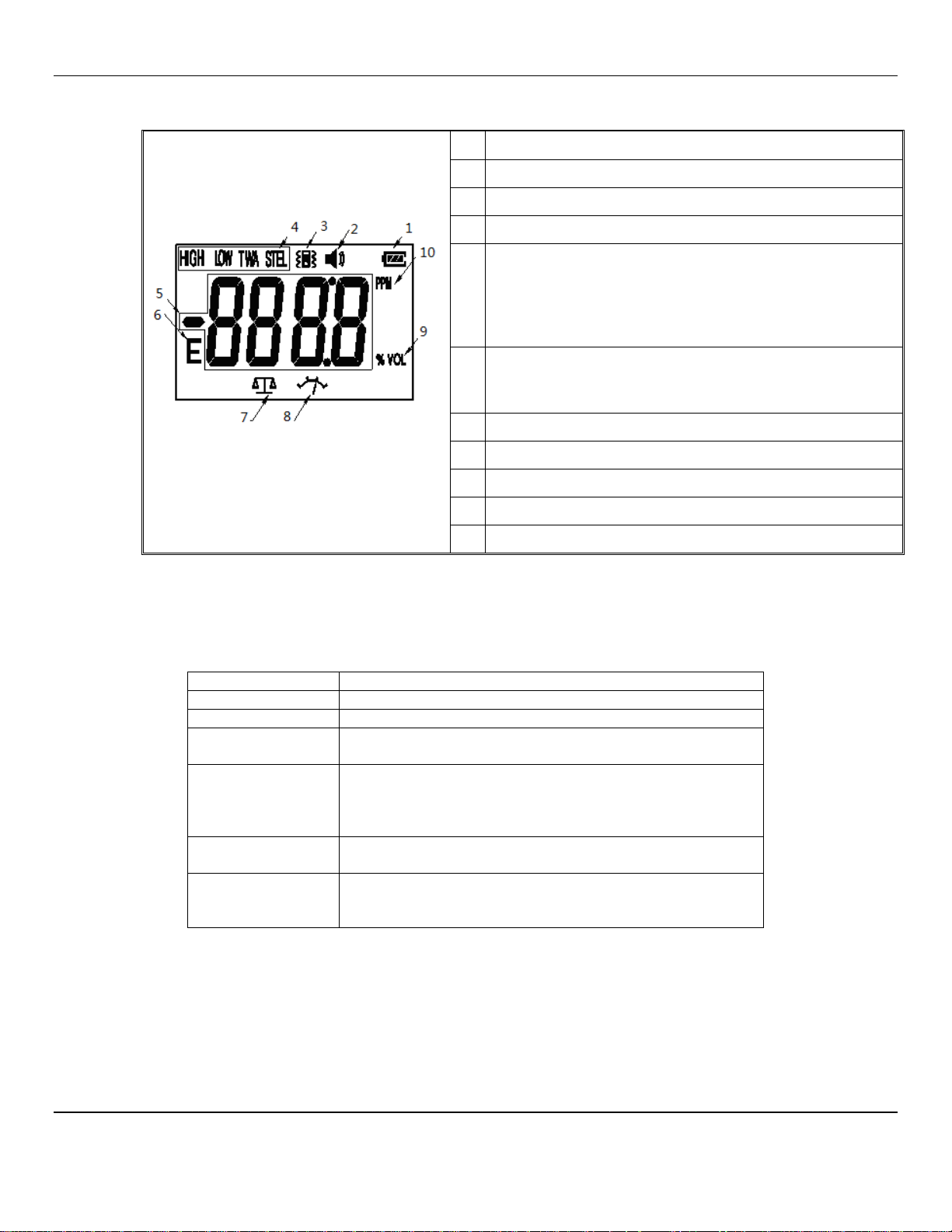
2.2 RECON-IS Display
See Figure 2 for location of indications.
Indication
Battery Status
1
Audio Alarm status
2
Vibration status
3
Alarm type:
4
HIGH, High alarm
LOW, Low alarm
TWA, Time weighted Average concentration
STEL, Permissible concentration short time explosive limit
4 Digit with negative and point indicators
5
Measurement Values
Information Codes
Error alert
6
Zero Calibration
7
Calibration Point
8
Percent by Volume Measurement
9
Figure 2: RECON-IS Display
Parts Per Million Measurement
10
2.3 RECON-IS Button Function
Easy operation through the single button: turn on or off the detector, mute, cancel vibration alarm, information checking,
activate/deactivate confidence beep, calibration etc. In different status, the function of the button is different as follows:
Function Action
Turn on Press it for 3 seconds when it is power off.
Turn off Press it for 3 seconds when it is power on.
Cancelling sound
or vibration alarm
Information
checking
Activate/Deactivate
Confidence Beep
Calibration
See Section 3 for more details of Button Functions.
When alarming, press it once.
In normal monitoring status, press it for 1 second, the
backlit is on, and the screen displays in turns STEL, TWA,
peak level, minimum level, confidence beep information
etc.
When the detector is being turned on, keep pressing it till
the screen displays, “H OP” or “H CL”.
Keep pressing it till the detector is power off and is again
turned on, the screen displays “CAL”, then release the
button, and the detector enters calibration status.
3
Page 6

RECON-IS ENMET
3.0 RECON-IS Operation
3.1 Turn On RECON-IS
Press and hold the button for 3 seconds, the detector will turn on. After this, the detector will start a following self test:
Example: RECON-IS CO
A. Display all the fields and graphs and light the backlight.
B. The buzzer gives sound.
C. The vibration and alarm indication pulse.
D. Display the version number:
E. Display the preset low alarming value and the high alarming value:
F. Display STEL and TWA levels:
G. Warm-up Completion:
After passing the self test, the detector starts warm-up, display shows 3, 2, 1. The unit is now operational and
mentoring for the target gas concentration in the area:
If the self test fails, the RECON-IS will turn off automatically. Please contact the ENMET for information.
3.2 Turn Off RECON-IS
In the normal monitoring status, hold the button till the buzzer gives sound 3 times and the screen displays “OFF”, “OFF3”,
“OFF2” and “OFF1” as shown in the following pictures:
After that, the screen is off. Release the button and the detector will be power off.
4
Page 7

RECON-IS ENMET
3.3 Information Checking
In the normal monitoring status, press and release the button twice to activate the backlite. Press the button for about 1 second
and the screen will display: STEL level, TWA level, Max. gas level (for toxic gas) or Min. gas level (for O2 only), confidence
beep status (on or off), zero calibration information, and data reset information.
STEL Level
TWA Level Max or Min Level that has been detected
Confidence Beep – ON Confidence Beep – OFF
Zero Calibration Data Reset
3.4 Confidence Beep
Only when the user is turning on the RECON-IS, can the confidence beep setting be changed. Follow these steps to change the
setting:
1. With the RECON-IS off.
2. Press and Hold the button during the turn on period continue to press the button until the unit coun ts down 3, 2, 1 continue to
hold the button until the screen displays “H oP”(ON) or “H CL”(OFF) release the button. The status of the confidence beep is
now changed.
Note: With the confidence beep turned on, the buzzer sounds once every 2 minutes, which indicates the detector is working
normally. If the confidence beep is turned off, there is no such indication when the detector is working normally.
3.5 Zero Calibration
In the clean air, if the test result is not accurate, please proceed to the zero calibration in the clean air.
The procedures are as follows:
During the information checking, when the screen displays “ZoF”, press and release the button quickly.
If the operation is successful, the buzzer gives sound once.
The zero calibration range is ±5% F. S.
3.6 Data Reset: Clear recorded STEL, TWA and Max/Min Levels
During the information checking, when the screen displays “rES”, press and release the button quickly.
If the operation is successful, the buzzer gives sound once. And the STEL value, TWA value, Max. Gas level (for toxic gas) or
Min. gas level (for O2) will be reset.
5
Page 8

RECON-IS ENMET
3.7 Alarm Information
Alarm type Information displayed
Low alarm:
Slow Pulsed tone alarm sound
Alarm LED Flashing
Vibration
High alarm:
Quick Pulsed tone alarm sound
Alarm LED Flashing
Vibration
STEL alert:
Quick Pulsed tone alarm sound
Alarm LED Flashing
Vibration
TWA alert:
Quick Pulsed tone alarm sound
Alarm LED Flashing
Vibration
Overrange alert:
Quick Pulsed tone alarm sound
Alarm LED Flashing
Battery low voltage alert:
log appears.
At this time, the detector can still work for 30
days at least. When the battery is used up, the
detector will turn off automatically.
Sensor end-of-life indication:
Within 0-9 days before the sensor is used up,
screen will display as the right picture shows
when the detector is self testing after turning on.
The figure means the number of the days
remaining.
Table 1: RECON-IS Range and Alarm Levels
Target gas Detecting Range Low alarm level High alarm level TWA level STEL level
H2S 0-100ppm 10ppm 15ppm 10ppm 15ppm
CO 0-1000ppm 35ppm 100ppm 25ppm 200ppm
O2 0-30%vol 19.5%vol 23.5%vol -- --
6
Page 9

RECON-IS ENMET
3.8 Calibration
In order to assure the testing accuracy, ENMET suggests that the RECON-IS be calibrated at a minimum of every 180 days.
The calibration procedures are as follows:
1. In clean air, press the button till the detector is turn ed off,
keep pressing the button, the detector will turn on again, the
screen displays time count-down of 3 second.
2. When the screen displays “CAL”, release the button and the
detector enters calibration status.
3. The detector will first calibrate the zero point. Please connect
the detector to the gas bottle and input high-pure N2 into the
detector at the speed of 120ml/min. Or put the detector in the
clean air and it will calibrate zero.
Not used for Oxygen
4. When the screen displays flashing calibration points, connect
the cylinder regulator, calibration gas and sensor cover to the
instrument. In 30 seconds display will indicate numbers
Example 1476 and continue to change until the sensor response
stabilizes If no gas input within 30s, the system treats the
calibration as failed.
5. If the standard gas is input normally, the detector will adjust
once every 3 seconds till the system is steady and the
calibration is finished. If calibration succeeded, the screen
displays “S” and returns to self-test, see section 3.1.
Remove the calibration gas Press & Hold the button until the
instrument turns off.
6. If calibration failed, the screen displays “F C” for 30 second.
During this period, the user can press the button to repeat the
calibration.
7. During the 30 seconds of “F C” flashing, if no operation, the
calibration failed. The screen will display “F” and the detector
turns off automatically.
Example:
Example CO, See Table 1
Calibration Gas Sensor Respinding to
Not used for Oxygen Calibration Gas
Calibration Cover
With tube connected
to regulator valve
Gas Cylinder with
Regulator Valve
Figure 3: RECON-IS with Calibration Adapter
7
Page 10

RECON-IS ENMET
4.0 Troubleshooting RECON-IS
Problem Possible reason Solution
The detector cannot be
turned on
No response to the gas
Testing not accurate
Gas level is negative Sensor drift Calibrate zero point
Zero calibration
unavailable
Battery used up
Circuit fault Contact the distributor or ENMET.
Warm-up not finished Wait till warm-up is finished
Circuit fault
Sensor is end-of-life
Not calibrated for long time Calibrate it in time.
Too much sensor drift Calibrate or replace the sensor
Please contact ENMET.
Contact the distributor or ENMET.
Contact the distributor or ENMET.
5.0 Sensor Replacement
Warning: the replacement sensor must be the same type as the sensor to be replaced.
Remove retaining screw, open the RECON-IS, pull out the present gas sensor (If the sensor is too tight, please shake it slightly
and then pull out it). And then put new gas sensor into the sensor socket. Make sure the sensor plug and socket is
corresponding. After replacement, screw on the retaining screw.
Caution: When plugging in the gas sensor, please don’t use too much pressure. Otherwise, the sensor may be damaged.
After replacement, please calibrate the sensor after the detector works for 30 minutes.
Sensor
Sensor Socket
Screw
Figure 4: Replacing RECON-IS Sensor
5.1 Replacement Sensors
ENMET replacement sensor part numbers:
Table 2: Sensor Part Numbers
Description of Part Part Number
Sensor H2S 02542-0200
Sensor O2 02542-1100
Sensor CO 02542-1200
NOTE: Contact ENMET or local distributor for additional sensor information.
8
Page 11

RECON-IS ENMET
6.0 Maintenance
In order for the RECON-IS to operate normally, please follow these maintenance procedures:
Inspect, test and calibrate the RECON-IS periodically. ENMET suggests that the RECON-IS be calibrated at a minimum of
every 180 days.
Keep a record of all the maintenance, calibration and alarms. After extended use, if there is dust on the cover of the detector,
clean it by using a clean soft cloth. Do not use an impregnated, soap and polishing reagent for cleaning. When clearing the gas
sensing hole, please use dry downy cloth or soft brush.
Please do not put the detector in any type liquid.
Changing the parts may be harmful to the inner safety of detector.
Do not use other sensor for your RECON-IS. Only use ENMET 02542- Series Sensor. See Section 5.1.
Only assigned model lithium battery 3V DC, 1300 mAh Panasonic CR123A allowed.
The RECON-IS is powered with a lithium battery do not discard with general waste. Dispose of battery per local
codes only
Unauthorized removal, adjustment or repair of the RECON-IS will influence the performance of the device and the
explosion-proof.
6.1 Maintenance Equipment
ENMET calibration equipment part numbers
Table 3: Calibration Gas and Maintenance Equipment
Description of Part Part Number
Cylinder, 40 ppm H2S 03314-040
Cylinder, 500 ppm CO 03219-500
Cylinder, 17% Oxygen by Vol.
for alarm check only Not calibration
Cylinder20.9% Oxygen by Vol. 03296-209
Regulator, Cylinder: CO, O2, Methane 02506-004
Regulator, Cylinder: H2S 02506-002
Sensor Cover 02543-027
Battery Lithium, 3VDC, 1300mAh or CR123A *Obtain form local source
*NOTE: Due to issues with shipping individual lithium batteries, users should purchase the battery from a local source.
Panasonic 3VDC, # CR123A, no substitution allowed for approval purposes.
Contact ENMET or local distributor for additional information.
03296-170
9
Page 12

RECON-IS ENMET
7.0 Technical Data and Specifications
Detection Method
Sensor
Detection Range & Alarm Levels
Operation Condition
Electrical Power
Operating Time
Charge Time
Expected Sensor Life
Ingress Protection
Approval Ratting
Dimensions
Weight
Natural Diffusion
Electrochemical Sensor
See Table 1
Temperature: -20°C – 55°C
Humidity: 5 – 95%RH non condensing
Lithium Battery, DC3.6v CR123A, Rechargeable
Continuous, Non-Alarm Conditions
Approximately:
8 Hours for Combustible (LEL) unit
300 Hours for CO, H2S & O2 units
4 – 6 Hours
2 years
IP 65
2.4 x 3.9 x 1.3 inches(60x100x33mm)
5 ounces (140g)
NOTE: All specifications stated in this manual may change without notice.
10
Page 13

RECON-IS ENMET
8.0 WARRANTY
ENMET warrants new instruments to be free from defects in workmanship and material under normal use for a period of one
year from date of shipment from ENMET. The warranty covers both parts and labor excluding instrument calibration and
expendable parts such as calibration gas, filters, batteries, etc... Equi pment believed to be defective should be returned to
ENMET within the warranty period (transportation prepaid) for inspection. If the evaluation by ENMET confirms that the
product is defective, it will be repaired or replaced at no charge, within the stated limitations, and returne d pre paid to any
location in the United States by the most economical means, e.g. Surface UPS/FedEx Ground. If an expedient means of
transportation is requested during the warranty period, the customer is responsible for the difference between the most
economical means and the expedient mode. ENMET shall not be liable for any loss or damage caused by the improper use of
the product. The purchaser indemnifies and saves harmless the com pany with respect to any loss or damages that may arise
through the use by the purchaser or others of this equipment.
This warranty is expressly given in lieu of all other warranties, either expressed or implied, including that of merchantability,
and all other obligations or liabilities of ENMET which may arise in connection with this equipment. ENMET neither assumes
nor authorizes any representative or other person to assume for it any obligation or liability other than that which is set forth
herein.
NOTE: When returning an instrument to the factory for service:
Be sure to include paperwork.
A purchase order, return address and telephone number will assist in the expedient repair and return of your unit.
Include any specific instructions.
For warranty service, include date of purchase
If you require an estimate, please contact ENMET.
There are Return for Repair Instructions and Form on the last pages of this manual. This Form can be copied or used as needed.
Manual Part Number
80006-022
October 25, 2012
MCN-472, 04/12/13
MCN-13-005, 09/12/13
MCN-14-005, 09/02/14
Notes:
11
Page 14

PO Box 979
680 Fairfield Court
Ann Arbor, Michigan 48106-0979
734.761.1270 Fax 734.761.3220
Returning an Instrument for Repair
ENMET instruments may be returned to the factory or any one of our Field Service Centers for regular repair
service or calibration. The ENMET Repair Department and Field Service Centers also perform warranty
service work.
When returning an instrument to the factory or service center for service, paperwork must be included which
contains the following information:
A purchase order number or reference number.
A contact name with return address, telephone and fax numbers
Specific instructions regarding desired service or description
of the problems being encountered.
Date of original purchase and copy of packing slip or invoice
for warranty consideration.
If a price estimate is required, please note it accordingly and be
sure to include a fax number.
Providing the above information assists in the expedient repair and return of your unit.
Failure to provide this information can result in processing delays.
ENMET charges a one hour minimum billing for all approved repairs with additional time billed to the closest
tenth of an hour. All instruments sent to ENMET are subject to a minimum evaluation fee, even if returned
unrepaired. Unclaimed instruments that ENMET has received without appropriate paperwork or attempts to
advise repair costs that have been unanswered, after a period of 60 days, may be disposed of or returned
unrepaired COD with the evaluation fee.
Service centers may have different rates or terms. Be sure to contact them for this information.
Repaired instruments are returned by UPS/FedEx Ground and are not insured unless otherwise
specified. If expedited shipping methods or insurance is required, it must be stated in your paperwork.
Note: Warranty of customer installed components.
If a component is purchased and installed in the field, and fails within the warranty term, it can be
returned to ENMET and will be replaced, free of charge, per ENMET’s returned goods procedure.
If the entire instrument is returned to ENMET with the defective item installed, the item will be replaced
at no cost, but the instrument will be subject to labor charges at half of the standard rate.
Page 15

Repair Return Form
Mailing Address:
ENMET
PO Box 979
Ann Arbor, Michigan 48106
Phone Number: 734.761.1270
FAX Number: 734.761.3220
Shipping Address:
ENMET
Attn: Repair Department
680 Fairfield Court
Ann Arbor, Michigan 48108
Your Mailing Address:
Contact Name: __________________________ Your Phone: _______________________
Your PO/Reference Number: _______________ Your FAX: _______________________
Payment Terms: COD
(Check one) VISA / MasterCard______________________ ________ ________
Card number Expiration Card Code
American Express______________________ ________ ________
Card number Expiration Card Code
Name as it appears on the credit card___________________________________
Your Shipping Address:
Return Shipping Method:
UPS: Ground 3 Day Select Next Day Air ND Air Saver 2-Day Air
UPS Account number: ________________________
Federal Express: Ground Express Saver P-1 Standard 2-Day Air
FedEx Account number: ________________________
Would you like ENMET to insure the return shipment?
No Yes Insurance Amount: $_________________
 Loading...