

ENMET Recon/NH3-B, Recon/CO-B, Recon/H2-B, Recon/O2-B, Recon/HS-B Operation And Maintenance Manual
...Page 1
ENMET
680 Fairfield Court
Recon B Series
Operation and Maintenance Manual
Ann Arbor, MI 48108
734.761.1270 Fax 734.761.3220
www.enmet.com
Page 2

Recon B Series
ENMET
Manual Revi s i on Date – June 15, 2017
Page | 1
Manual Part No. – 80006-023
!
Table of Contents
INTRODUCTION ..............................................................................................................................................................................2
1.0
1.1 Unpack ....................................................................................................................................................................................................... 2
1.2 Check Order ............................................................................................................................................................................................... 2
1.3 Serial Numbers ........................................................................................................................................................................................... 2
FEATURES .....................................................................................................................................................................................3
2.0
2.1 Recon/B Series Features............................................................................................................................................................................. 3
3.0
DESCRIPTION OF PUSHBUTTONS .....................................................................................................................................................4
4.0
OPERATION ...................................................................................................................................................................................5
4.1 Activation of the Recon B Series ............................................................................................................................................................... 5
4.2 Deactivation of the Recon B Series ............................................................................................................................................................ 5
4.3 Checking Recon/B Series Status ................................................................................................................................................................ 6
4.4 Recon/B Series Operational Perimeters ..................................................................................................................................................... 6
4.5 Alarms ........................................................................................................................................................................................................ 7
4.6 Automatic Zero Calibration ....................................................................................................................................................................... 8
MAINTENANCE OF THE RECON/B SERIES .........................................................................................................................................9
5.0
5.1 Calibration of the Recon/B Series .............................................................................................................................................................. 9
5.1.2 Zero calibration .................................................................................................................................................................................. 9
5.1.3 Calibration Point Adjustment ........................................................................................................................................................... 10
5.2 Alarm Levels Adjustment of the Recon/B Series ..................................................................................................................................... 11
5.2.1 Set up of L-alarm (Low Alarm) ......................................................................................................................................................... 11
5.2.2 Set up of H-alarm (High Alarm) ....................................................................................................................................................... 11
5.3 Battery Charging ...................................................................................................................................................................................... 11
5.4 Sensor Replacement ................................................................................................................................................................................. 12
SPECIFICATIONS AND TROUBLESHOOTING TIPS .............................................................................................................................12
6.0
6.1 Specifications ........................................................................................................................................................................................... 12
6.2 Troubleshooting Tips ............................................................................................................................................................................... 12
7.0
ACCESSORIES AND REPLACEMENT PARTS .....................................................................................................................................13
7.1 Replacement Sensor part numbers ........................................................................................................................................................... 13
7.2 Parts and Accessories ............................................................................................................................................................................... 13
7.2 Calibration Equipment and Gas ............................................................................................................................................................... 13
TERMS AND CONDITIONS ..............................................................................................................................................................14
8.0
8.1 Ordering Information ............................................................................................................................................................................... 14
8.2 Delivery .................................................................................................................................................................................................... 14
8.3 Payment Terms ........................................................................................................................................................................................ 14
8.4 Warranty Information and Guidelines ...................................................................................................................................................... 14
8.5 Return Policy ............................................................................................................................................................................................ 14
INSTRUCTIONS FOR RETURNING AN INSTRUMENT FOR SERVICE ......................................................................................................15
9.0
List of Figures
Figure 1: Recon B Series Features ....................................................................................................................................................................... 3
Figure 2: Recon B Series Display ........................................................................................................................................................................ 4
List of Tables
Table 1: Recon/B Series Factory Set Parameters ............................................................................................................................................... 12
Reference Information:
OTE: [important information about use of instrument]
N
AUTION: [affects equipment – if not followed may cause damage to instrument, sensor etc.…]
C
ARNING: [affects personnel safety – if not followed may cause bodily injury or death.]
W
Attention / Warning
Earth Ground
Page 3

Recon B Series
ENMET
Manual Revi s i on Date – June 15, 2017
Page | 2
Manual Part No. – 80006-023
Items included with the Recon/B Series:
Manual
ENMET
Toll Free: 800-521-2978
1.0 Introduction
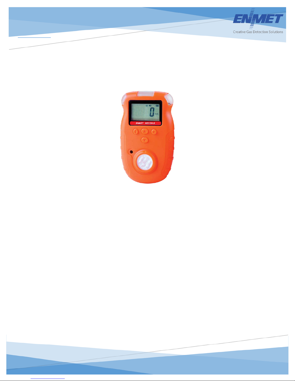
The RECON/B SERIES is a portable-single gas detector for detection of combustible or toxic gases. It is intended for detection of
combustible or toxic gas in commercia l or industrial facilities to keep workers safe, and/or detect a potentially explosive gas
environment.
The Recon/B Series, adopting excellent-quality sens or, makes detectio n i n the way of natural diffusion. It has good sensitivity and
reproducibility. The detector adopts embedded MCU controller, easy to operate.
The Recon/B Series incorporates a special high strength, anti-slip rubber case providing anti slip handle ability.
The Recon/B Series has an ingress protection rating of 65.
NOTE: All specifications stated in this manual may change without notice.
1.1 Unpack
Unpack the Recon/B Series and examine it for shipping damage. If such damage is observed, notify both ENMET customer
service personnel and the commercial carrier involved immediately.
Regarding Damaged Shipments
OTE: It is your responsibility to follow these instructions. If they are not followed, the carrier will not honor any claims for
N
damage.
This shipment was carefully inspected, verified and properly packaged at ENMET and delivered to the carrier in good
condition.
When it was picked up by the carrier at ENMET, it legally became your company’s property.
If your shipment arrives damaged :
Keep the items, packing material, and carton “As Is.” Within 5 days of receipt, notify the carrier’s local office and
request immediate inspection of the carton and the contents.
After the inspection and after you have received written acknowledgment of the damage from the carrier, contact
ENMET Customer Service for return authorization and further instructions. P le a se have your Purchase Order and Sales
Order numbers available.
ENMET either repairs or replaces damaged equipment and invoices the carrier to the extent of the liability coverage, usually
$100.00. Repair or replacement charges above that value are your company’s responsibility.
The shipping company may offer optional insurance coverage. ENMET only insures shipments with the shipping company
when asked to do so in writing by our customer. If you need your shipments insured, please forward a written request to
ENMET Customer Service.
Regarding Shortages
If there are any shortages or questions regarding t his shipment, please notify ENMET Customer Service within 5 days of receipt at
the following address:
Instrument
Charger
Screwdriver
1.2 Check Order
Check, the contents of the shipme nt against t he purchase order. Verify that the Recon/B Series is received as ordered. Each
Recon/B Series is labeled with its target gas. If there are accessories on the order, ascertain that they are present. Check the
contents of calibration kits. Notify ENMET customer service personnel of any discrepancy immediately.
1.3 Serial Numbers
Each Recon/B Series is serialized. These numbers are on tags on the equipment and are on record in an ENMET database.
680 Fairfield Court
Ann Arbor, MI 48108
734-761-1270 Fax 734-761-3220
Page 4
Recon B Series
ENMET
Manual Revi s i on Date – June 15, 2017
Page | 3
Manual Part No. – 80006-023
Feature
Description
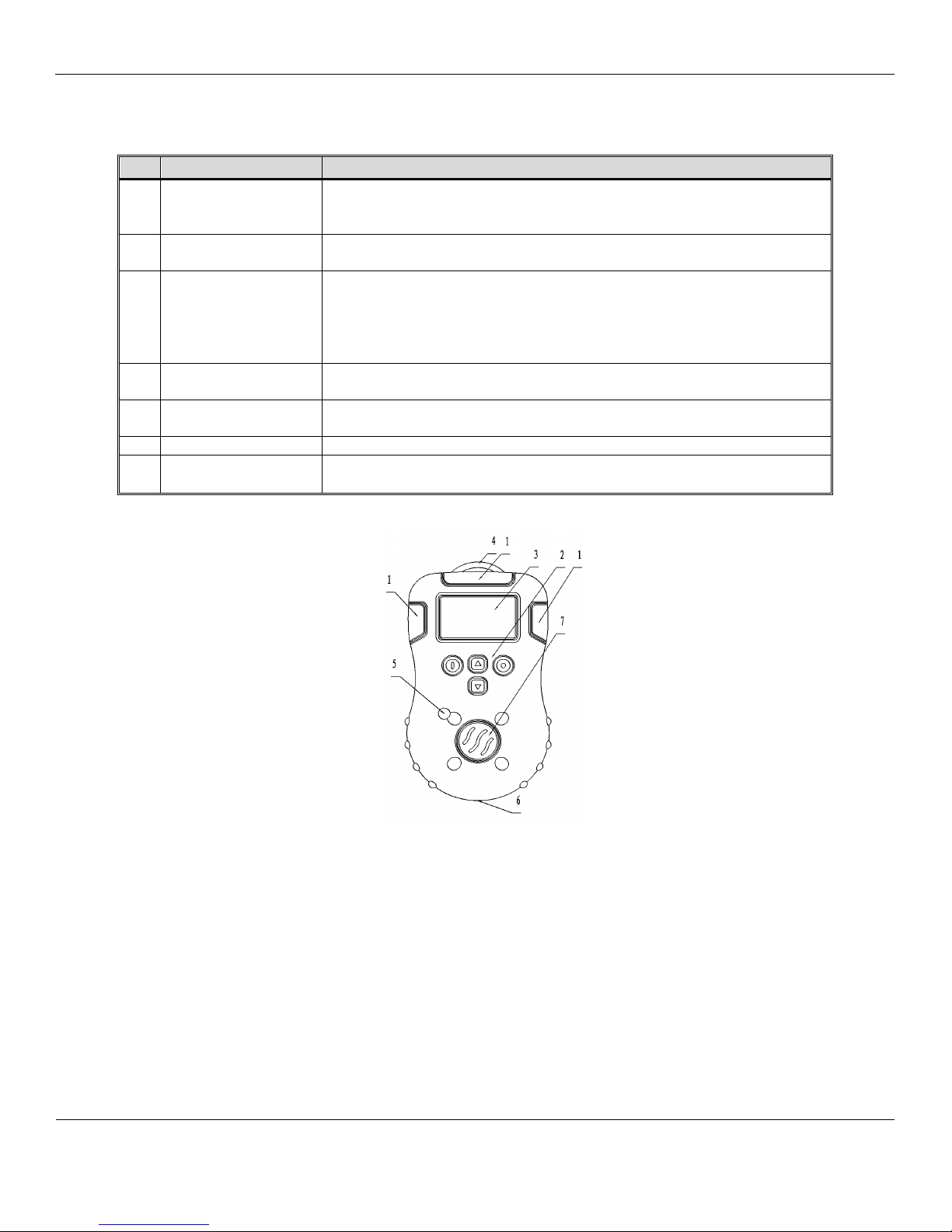
1
Visual Alarms
Red indicators clearly visible on 3 sides and located at the top of the Recon/B
LED’s activate when alarm thresholds are exceeded
2
Pushbuttons
P
, UP, SET and D
Buttons
See section 3.1 for description of each pushbutton
3
Display
The Liquid Crystal Display (LCD) allows messages to be read clearly:
maintenance mode etc.…
4
Belt Clip
Clip to outside of clothing for hands-free operation
Attached to back of the instrument
5
Audio Alarm
Loud buzzer located on the front of the instrument
The audio alarm (Buzzer) is on when the unit is in alarm.
6
Charging Socket
Battery Char gi ng Connection, to plug in battery charger
7
Sensor
Located in front of the Recon/B Series
• Type varies depending on the target gas
Front View
2.0 Features
2.1 Recon/B Series Features
See Figure 1 for location of features:
Series
OWER
• 4 digits (7 segme nt s ), for displaying the measurement
• pictograms symbols used to indicate supplementing the audio and
visual alarms relating to the exceeding of thresholds, battery faults,
OWN
Figure 1: Recon B Series Features
Page 5
Recon B Series
ENMET
Manual Revi s i on Date – June 15, 2017
Page | 4
Manual Part No. – 80006-023
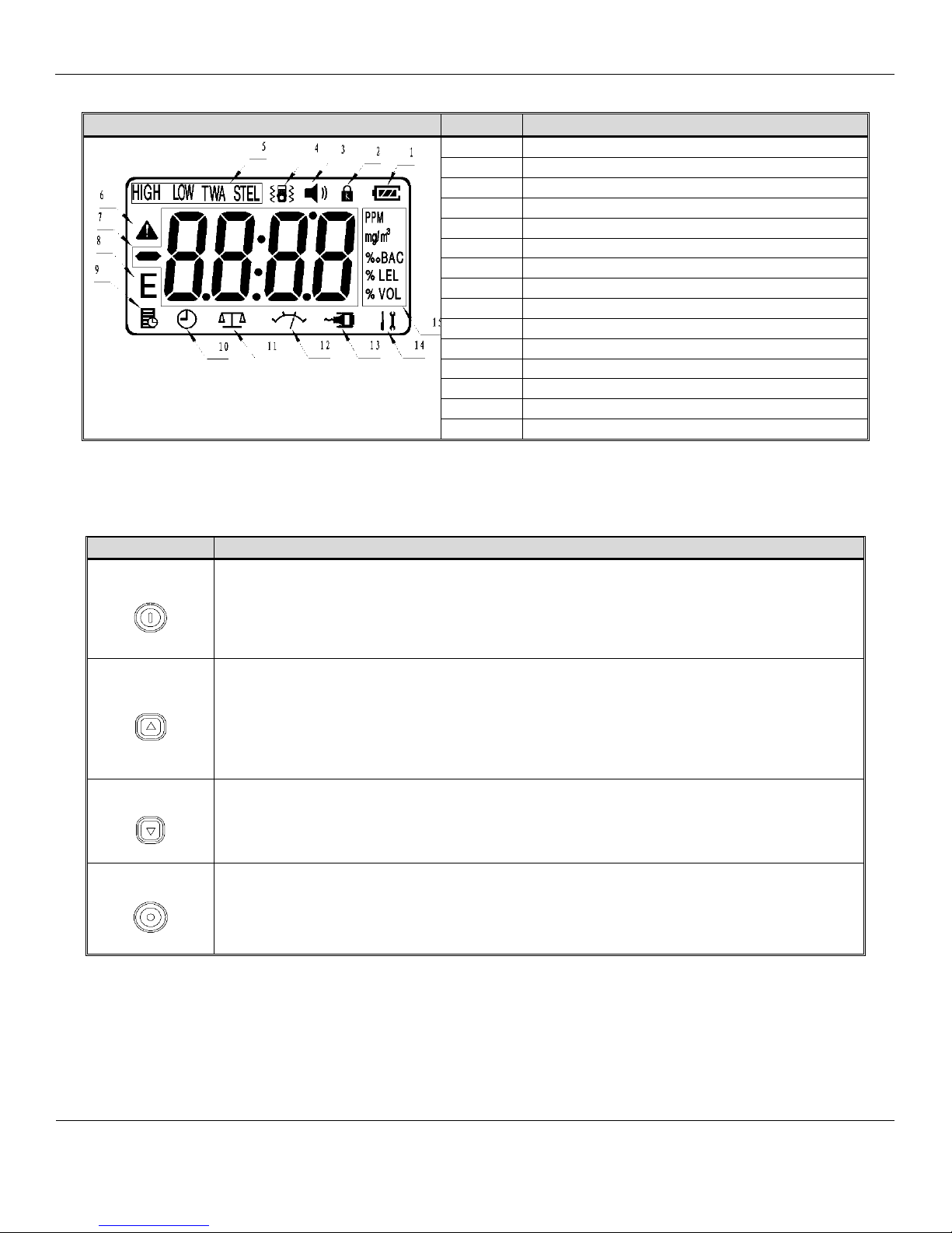
LCD, Display
Number
Function
1
Battery
2
Lock
3
sound
4
vibration
5
Alarming conditions
6
Warning or the maximum level
7
numeric value
8
Error
9
Not Used
10
Clock
11
Zero calibration
12
Calibration point or calibration status
13
Not Used
14
Set-up of the parameters
15
Indication of the gas concentrati on units
Push Button
Function Description
3.0 Description of Pushbuttons
Figure 2: Recon B Series Display
POWER
UP
DOWN
SET
Activate / deactive the instrument, press and hold it for 3 seconds
Maintenance operations, See section 4
Cancel an operation
Increase the display value
Check the instrument status the LCD will display Temp. °C, time, STEL & T WA levels, maxium
level, see section 4
Set up the instrument parameters, see section 4
Decrease the display value
Maintenance operations, See section 4
Confirmation of the parameters set-up
Maintenance operations, See section 4
Page 6
Recon B Series
ENMET
Manual Revi s i on Date – June 15, 2017
Page | 5
Manual Part No. – 80006-023
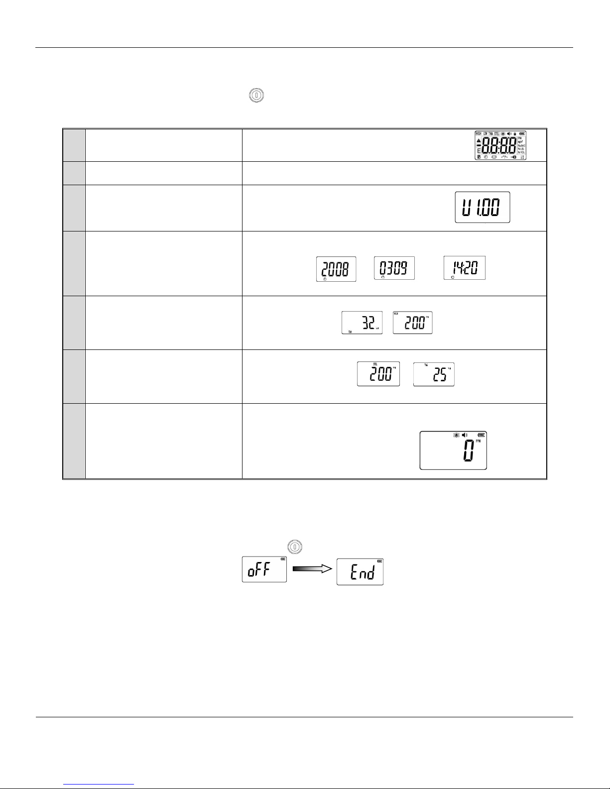
1
Display Test
The LCD displays all of the screen elements.
2
Alarm Function Test
The audio alarm beeps, the visual alarm flashes the backlight activates
briefly and the detector emits one vibra tion
3
Indication of Version
Displays software version
4
Date and Time
Displays the date and time auto matically in the following order:
5
Indication of Alarm settings
Displays Low Alarm level then High Alarm level
6
Indication of STEL and TWA
Displays STEL then TWA levels
7
Warm Up Count Down
If detector passes the self-test, it enters a short warm up count down.
Year
Month & Date
Hour & minute
L-alarm
H-alarm
STEL
TWA
4.0 Operation
4.1 Activation of the Recon B Series
To activate the detector, press the POWER button and hold for 3 seconds.
The detector begins a self-test sequence, example listed below
Year, Month & Date, Hour & Minute
Example: CO
For toxic instruments only
for toxic instruments only
Example: CO
3 – 30 seconds, depending on type of gas sensors installed.
Then displays ambient gas readi ng.
Example: CO in clean air
Proper op eration of the Recon B Series requires that the instrument be zeroed. With the Recon/B Series ON and in clean air, the
display should read 0 or 20.9 for oxygen units. See Section 4.6.
4.2 Deactivation of the Recon B Series
To deactivate the Recon/B Series, press the POWER button and hold for 3 seconds.
The Recon/B Series will “beep” and display:
Page 7

Recon B Series
ENMET
Manual Revi s i on Date – June 15, 2017
Page | 6
Manual Part No. – 80006-023
Display
Function
C
: If you change the
Does Not affect Alarm Audio
button to change. Then press SET button.
4.3 Checking RECON/B SERIES Status
To activate the detector, press the POWER button and hold for 3 seconds.
When the Recon/B Series has finis hed its startup sequence. Press UP
and SET buttons at the sa me time, the display will
indicate Temp., time, STEL & TWA levels (for toxic) and maximum level
4.4 RECON/B SERIES Operational Perimeters
In this menu, you can ad just: Time, Date, change instrument password, Activate/Deactivate the audio associated with the
pushbuttons switches and Activate/Deactivate the vibratory alarm.
With the Recon/B Series activated, press and hold the UP
Recon/B Series menu options press the D
OWN button to scroll through the option.
and DOWN buttons at the sa me time until the display
Press SET button to select dat e
and time adjustment
AUTION
password for the factory set
password 1270, record your new
password for fu t ure reference.
Press S
ET button to select the
Change Password option.
Press the S
ET button and enter
the new password.
Use the UP
and DOWN
buttons to incroment digit.
ET button to accept digit
Use S
and advance the cursor.
Not Used
Press S
ET button to select
Sound ON or OFF
Use the UP
S
ET button to accept and advance to next option
and DOWN buttons to adjust display and
Will be displayed. Then press SET button.
Will be displayed. Enter the Old pa ssword. When
the correct Old password is entered,
will be displayed.
Then enter the new password.
When the last digit is entered,
will be displayed. Re-enter the new password.
When the completed password is entered, the display will show
the date information.
Press SET button to accept disp lay indication or Use the UP
button to change. Then press SET button.
Press SET button to select
Vibration ON or OFF
To exit without saving the option s tate change, press the P
N
OTE: using the UP button reverses the menu.
Press S
OWER button.
ET button to accept display indication or Use the UP
Page 8

Recon B Series
ENMET
Manual Revi s i on Date – June 15, 2017
Page | 7
Manual Part No. – 80006-023
Alarm Type
Display
Low Alar m
High Alarm
High concentration protection ↑
Sensor Fault
STEL alarm
TWA alarm
Over F. S. alarm
4.5 Alarms
When alarmi ng continuously, you can press SET button to turn off the audible alarm and vibration
when the and are flashing.
The following table describes Recon/B Series alarms and shows examples of display for each alarm.
Slow tone
Flash
Vibration ←
Fast tone
Flash
Vibration ←
Slow tone
Flash
Fast tone
Slow tone
Flash
Vibration ←
Slow tone
Flash
Vibration ←
Slow tone
Flash
Page 9

Recon B Series
ENMET
Manual Revi s i on Date – June 15, 2017
Page | 8
Manual Part No. – 80006-023
Time error
Memorizer error
Low voltage
off.
Status
Example of Display
NOTE: Incorrect password will exit auto zero menu.
In this condition, the device will try to renovate it by itself.
If succeeded, after start-up, it enters the menu of time set up.
Please set up the time according to the local time. If failed,
the device will turn off. Please contact the supplier for
repair.
When detecting, the device will try to renovate it by itself. If
failed, it will turn off. Please contact the supplier for repair.
Modified tone alarming sound per second
If the serious low voltage, the icon will flicker. Then
the device can continue t o work for 15 min at most.
Please recharge it at a safe place, otherwise it will turn
NOTES: ← If vibration option is On - ↑ For Combustible gas
4.6 Automatic Zero Calibration
In clean air, if detecting value is not 0, choose this function to make the zero calibration.
With Recon/B Series On, press both D
OWN and SET buttons for 1 second.
Press both DOWN and SET buttons.
After 1 second, it advances to the next status
When 0000 is displayed:
Enter the password, factory set to 1270, by using the UP button to
increment the digit and the S
ET b utto n to a c c ept the indicated digit
and move the cursor. When the correct password is entered, the display
will advance.
When display is sta ble. Press SET button to confirm the operation.
OTE: the display may not indicate 0 prior to confirmation.
N
OTE: Not applicable for oxygen instruments.
N
Page 10

Recon B Series
ENMET
Manual Revi s i on Date – June 15, 2017
Page | 9
Manual Part No. – 80006-023
Connect the calibration cover to the in str ument, attach the regulator to the gas
cylinder.
5.0 Maintenance of the Recon/B Series
To maintain proper battery function and life the Recon should be operated once a week for 6 to 8 hours and then placed on charge see
Section 5.3
The Recon/B Series maintenacne section allows access to Zero, Calibration, Calibration target gas and alarm point adjustment menus.
To enter the maintenance menus section you must start with the instrument OFF.
ARNING: As all the parameters of this mode may endanger the safety of the operator, so please perform the operation carefully
W
5.1 Calibration of the Recon/B Series
With the instrument OFF, press P
hold for 5 seconds, the R
ECON/B SERIES begins a self-test. If the self-test
OWER amd SET buttons and
passes, then after a short time, it indic a te s r e quest for password.
Enter the password, factory set to 1270, by using the UP button to
increment the digit and
ET button to accept the indicated digit and move the cursor.
the S
A display of 30 will appear and count down to 0.
Only when t he correct password is entered can the detector enter the maintenance menu.
If there is no operation or the password is wrong, the detector will be deactivated. So, please input the correct password in time.
5.1.2 Zero calibration
ARNING: This operation should be carried out in the clean air. Otherwise the accuracy of the detector will be affected.
W
When entering the next mode, if the displays shows E, the air is not clean, or the sensor is destroyed. Choose another
calibration location or replace the sensor.
OTE: Not used with Recon Oxygen units.
N
At this time, if S
Recon/B Series will accept the present concentration as the zero point, and then
enters into the mode of calibration point set up.
ET button is pressed or no operation within 1 minute, the
To Exit press P
P
OWER button advance and exit.
OWER button, menu will b ypass the calibration step to enter into the mode of alarming level set up, press
Page 11

Recon B Series
ENMET
Manual Revi s i on Date – June 15, 2017
Page | 10
Manual Part No. – 80006-023
NOTE: 20.9% Oxygen is the only calibration level to be used with Recon Oxygen units
Open the valve on the regulator
In 2 to 3 minutes the Recon/B Series will automatically adjust the conversion
Remove calibration cover from instr ument.
To exit calibration menu.
5.1.3 Calibration Point Adjustment
In this mode, display is the last concentration of gas used to calibr a te the
instrument. Pr ess UP or Down button to modify the display.
OTE: Not used with Recon Oxygen units
N
Within 30 seconds, if the Recon/B Series detects the calibration ga s, it will start
up the calibration date analysis procedure by itself. Continue gas flow.
The Display
will indicate gas level
as gas is detected
arithmetics to complete the gas response process. Then the Recon/B Series
saves the best arithmetics to complete calibration.
ARNING: The RECON/B SERIES must self-calibrate, please avoid touching
W
any buttons, otherwise the accuracy will be effected badly.
After that it enters into the L-alarm set up. Pre ss P
OWER button twice to
advance and exit.
If the Recon/B Series cannot reach half the calibration figure within 30 seconds, or the gas concentration is outside the
maximum drift range of the sensor, the E icon will light and 0000 will be displayed. This means the gas is not proper for
calibration or the sensor is deple te d.
Verify calibration gas is correct. If correct retry calibration sequence. If failure occurs sensor may need to be replaced.
Press the SET butt on then
Press SET button 3 times and then the POWER button 4 times.
Press P
OWER button
Page 12

Recon B Series
ENMET
Manual Revi s i on Date – June 15, 2017
Page | 11
Manual Part No. – 80006-023
Recon/B Series CO, H2S, O2
30+ Hours, non-alarm condition: Recharge time: approximately 4 – 6 hours
Recon/B Series for %LEL CH4
8 hours, non-alarm condition: Recharge time: approximately 6 hours
5.2 Alarm Levels Adjustment of the Recon/B Series
5.2.1 Set up of L-alarm (Low Alarm)
With the Recon/B Series Off press a nd hold the POWER and SET buttons until unit activates.
When 0000 is displayed, enter the password, factory set to 1270, by using the UP button to i ncrement the digit and t he S
button to accept the indicated digit and move the cursor. When the correct password is entered, the display will advance.
ET
Press the P
OWER b utton to advance to alarm set menu.
In this mode, the L-alarm level can be adjusted. Press UP or Down button to adjust the flickering figure according to
your need, and then press S
ET button to complete the set up. After that, it enters the H-alarm set up.
OTE: The display will not allow an unacceptable alarm level.
N
5.2.2 Set up of H-alarm (Hig h A la r m)
01In this mode, the H-alarm level can be adjusted. Press UP or Down button to adjust the flickering figure according
to your need , and then press S
ET to complete the set up. Afte r that the detector will automatically turn off.
OTE: The display will not allow an unacceptable alarm level.
N
5.3 Battery Charging
When the battery voltage is low, the Recon/B Series will no t function properly.
To recharge the batteries of the Recon/B Series: The Recon/B Series must be Off, connect the AC connector plugs of the charger
to a 110V
indicates that it is being charged. When the charging cycle is completed, the display will indicate full charge.
W
adversely affected. Always charge the battery in normal ambient air. Do not charge the Recon/B Serie s in a hazardous area to
be monitored, to avoid fire or explosion. Disconnect the charger after 24 hours, failure to do so will damage the battery.
AC or 220VAC outlet and plug t he charging cable into the Recon/B Series. The detector will activate automatically and
ARNING: DO NOT start the battery charge process with the Recon/B Series power on; otherwise the charge speed will be
Typical expected battery life and time to recharge:
OTE: To maintain proper battery function and life the Recon should be operated once a week for 6 to 8 hours and then placed on
N
charge.
Page 13

Recon B Series
ENMET
Manual Revi s i on Date – June 15, 2017
Page | 12
Manual Part No. – 80006-023
Model
Gas
Range
Low Alarm
High Alarm
TWA
STEL
Cal Gas
Recon/NH3-B
Ammonia
0-100ppm
25ppm
50ppm
25ppm
35ppm
Recon/CO-B
Carbon Monoxide
0-1000ppm
35ppm
100ppm
25ppm
200ppm
500ppm
Recon/H2-B
Hydrogen
0-1000ppm
35ppm
250ppm
N/A
N/A Recon/HS-B
Hydrogen Sulfide
0-100ppm
10ppm
15ppm
10ppm
15ppm
40ppm
Recon/O2-B
Oxygen
0-30%vol
19.5%vol
23.5%vol
N/A
N/A
20.9%
Recon/SO-B
Sulfur Dioxide
0-100ppm
2ppm
5ppm
2ppm
5ppm
Recon/EX-B
Methane
0-100%LEL
10%LEL
50%LEL
N/A
N/A
50%LEL
Recon/EX-B
Propane
0-100%LEL
10%LEL
50%LEL
N/A
N/A
3.6VDC Lithium battery,1200 mAh
Rechargeable
Working time continuous, non-alarm
conditions
Combustible gas: Approximately 8 hours
Toxic gas: Approximately 300 hours
Charge time
4 to 6 hours
Temperature:
–20°C to +50°C
Relative Humidity
5 to 95% RH, non-condensing
Dimensions:
2.4 x 3.9 x 1.3 inches (60 x 100 x 33 mm)
Weight:
5 oz. (140g) including battery
Ingress Protection
IP 65
Approval
Designed to be intrinsically safe
Malfunction
Possible Reasons
Solutions
low voltage
Charge Battery
Detector Fault
Contact ENMET
Circuit malfunction
Contact ENMET
Exhausted Sensor
Replace Sensor
Circuit malfunction
Contact ENMET
Exhausted sensor
Replace the sensor
Overdue Calibration
Calibrate
5.4 Sensor Replacement
Sensor life in the Recon/B Series is typically: 2 years for Carbon Monoxide & Hydrogen Sulfide and 1year for Oxygen and
Combustible.
The sensor needs to be replaced when the Recon/B Series can no longer be calibrated or if the sensor becomes erratic.
Contact ENMET for sensor replacement information.
Table 1: Recon/B Series Factory Set Parameters
6.0 Specifications and Troubleshooting Tips
6.1 Specifications
Working Voltage
Electrical Power
Operation
Mechanical
OTE: All specificatio ns stated in this manual ma y change without notice.
N
6.2 Troubleshooting Tips
Unable to Turn on the detector
No reaction to the tested gas
Inaccurate indication
Wrong time display
Exhausted b attery Charge and reset the time
Electromagnetic disturb Reset the time
Zero calibration function failed Too much dri ft Calibrate or replace the sensor
Page 14

Recon B Series
ENMET
Manual Revi s i on Date – June 15, 2017
Page | 13
Manual Part No. – 80006-023
Sensor, % LEL Combustible Gasses
02542-005
Sensor, CO
02542-1200
Sensor, H2S
02542-0200
Sensor, Oxygen
02542-1100
Sensor, H2
02542-1500
Sensor, NH3
02542-2400
Sensor, SO2
02542-0500
Aspirator*, with 27-inch probe and 3-foot hose
(Not suitable for reactive gas, H2S, Nh3, SO2)
02602-010
Aspirator*, with 12-foot hose
(Not suitable for reactive gas, H2S, Nh3, SO2)
02602-011
Motorized Sample Pump*, with 15-foot hose and 8-inch probe (for Recon/4 & Recon-B)
03700-053
Manual, Motorized Sample Pump
80021-025
Sensor Cover Assembly, for R econ-B
02543-029
Charger, 100-240 VAC, American style plug
02615-001
Manual, Recon-B Series
80006-023
Gas Regulator Assembly*, for 34-liter steel gas cylinder (CO & O2)
02506-004
Gas Regulator Assembly*, for 34-liter aluminum gas cylinder (CO & O2)
02606-002
Sensor Cover Assembly, for R ECON-B
02543-029
Cal/Zero Gas, 34-liter steel gas cylinder, 20.9% Oxygen, O2
03296-209
Calibration Gas, 34-liter steel gas cylinder, 50%LEL Methane, CH4
03220-050
Calibration Gas, 34-liter steel gas cylinder, 50%LEL Propane, C3H8
03221-050
Calibration Gas, 34-liter steel gas cylinder, 500ppm Carbon Monoxide, CO
03219-500
Calibration Gas, 34-liter steel gas cylinder, 500ppm Hydrogen, H2
03227-500
Calibration Gas, 34-liter aluminum gas cylinder, 40ppm Hydrogen Sulfide, H2S
03314-040
Calibration Gas, 34-liter aluminum gas cylinder, 50ppm Ammonia, NH3
03318-050
Calibration Gas, 34-liter aluminum gas cylinder, 10ppm Sulfur Dioxide, SO2
03315-010
Case, Calibration Equipment
Holds: Gas Regulator, Calibration Adapter and up to two 34 liter Cal Gas Cylinders
73083-000
7.0 Accessories and Replacement Parts
7.1 Replacement Sensor part numbers
7.2 Parts and Accessories
*Sensor Cover Assembly 02543-029 sold separately.
7.2 Calibration Equipment and Gas
*Sensor Cover Assembly 02543-029 sold separately.
Page 15

Recon B Series
ENMET
Manual Revi s i on Date – June 15, 2017
Page | 14
Manual Part No. – 80006-023
Phone: 734-761-1270
Fax: 734-761-3220
8.0 Terms and Conditions
8.1 Ordering Information
Address orders to:
ENMET
Attention: Customer Service Dep a rtment
680 Fairfield Court
Ann Arbor, MI 48108
Email Orders: orderentry@enmet.com
You may also contact our customer service department by email info@enmet.com. MINIMUM ORDER IS $50.00.
8.2 Delivery
Unless Seller otherwise specifies, delivery will be made: FOB Ann Arbor, MI and/or FOB Bowling Green, KY. Title and risk of
loss shall pass to Buyer at that po int. Shipping and handling charges will be Prepaid and Added to Buyer’s invoice. Buyer may
request shipping be charged to their own account with a preferred carrier. Seller shall have the right to choose means of
transportation and to route shipment when specific instructions are not included with Buyer’s order. Seller agrees to deliver the
goods and services, within the time, in accordance with specifications, at the prices specified on the face hereof. Buyer’s orders to
this quotation are not subject to c a ncella tion or deferment of delivery without indemnification of loss to the Seller resulting there
from. Seller shall not be liable to Buyer for any loss or damage sustained on account of this delay or nonperformance due to
causes beyond Seller’s control and without his fault or ne gligence. Where performance of the terms her e is contingent upon timely
delivery of goods or services by the Buyer and such delivery is in default, Seller shall be indemnified for any damage or loss
resulting there fro m, a nd/or by extension of Seller’s delivery commitment, as applicable.
8.3 Payment Terms
Payment Terms are Net 30 Days from the date of shipment from Seller unless otherwise noted. All shipping and handling costs
will be charged to Buyer on a Prepaid and Add basis. Buyer has the option of paying for shipping by charging its own account
with a carrier
8.4 Warranty Information and Guidelines
The Seller warrants new instruments to be free from defects in workmanship and material under normal use for a period of one
year from date of shipment. The warrant covers both parts and labor excluding calibration and expendable parts such as filters,
detector tubes, batteries, etc. If the inspection by the Seller confirms that the product is defective, it will be repaired or replaced at
no charge, within the stated limitations, and returned prepaid to any location in the United States. The Seller shall not be liable for
any loss or damage caused by the improper use or installation of the product. The Buyer indemnifies and saves harmless the Seller
with respect to any loss or damages that may arise through the use by the Buyer or ot hers of this equipment. This warranty is
expressly given in lieu of all other warranties, either expressed, implied or statutory, including that of mer c hantability, and all
other obligations, or liabilities of ENMET, LLC for damages arisin g out of or in connectio n with the use or repair or performance
of the product. In no event shall ENMET, LLC, be liable for any indirect, incidental, special or consequential damages or for any
delay in the performance by ENMET, LLC, which may arise in connection with this equipment. ENMET neither assume s nor
authorizes any representatives or other persons to assume for it any obligation or liability other than that which is set forth herein.
Buyer agrees to indemnify and save harmless Seller for any damage or loss from lawsuits against Seller by reason of manufacture
of sale of materials, parts, or use of processes resulting from Buyer’s design specifications. Any patent, design, pattern, tool, die,
jig, fixture, drawing, test equipment, or process furnished by Seller; whether possessed by the Seller before the date of this
quotation, or devised or acquired by Seller during performance of the terms of this quotation, shall remain the property of the
Seller except by specific stipulation on the face hereof. Seller reserves the right, without liability, for damage or loss, to destroy
Buyer’s drawings, specifications, patterns and special tools supplied by Buyer for performance of the terms on the face hereof,
unless Buyer gives noti ce of the disposition of such items.
8.5 Return Policy
All returns for credit must be approved in advance by ENMET, LLC. Such returns are subject to a minimum $50.00 or 20%
restocking charge, whichever is greater. Approval of equipment for return is totally at the discretion of ENMET, LLC. All
requests for return/exchange must be made no later 30 days of the original shipping date from ENMET. The actual amount of any
resulting credit will not be determined prior to a complete inspection of the equipment by ENMET. Calibration gas cylinders
cannot be returned or restocked.
Page 16

Recon B Series
ENMET
Manual Revi s i on Date – June 15, 2017
Page | 15
Manual Part No. – 80006-023
9.0 Instructions for Returning an Instrument for Service
Contact the ENMET Service Department for all service requests.
Phone: 734-761-1270
Email: repair@enmet.com
Fill out the “Service Request Fo rm” found at the end of t hi s manual and return with your instrument for all needs. Please send your
instrument for service to the site in which the product was purchased. A new “Service Request Form” may be requested if the one
found in the manual is not available. All instruments should be shipped prepaid to ENMET.
Address for Service:
Michigan Location:
Kentucky Locatio n:
Providing the “Service Request Form” assists in the expedient service and return of your unit and failure
to provide this information can re su lt in p rocessing delays. ENMET charges a one hour minimum billing for all a pproved repairs with
additional time billed to the closest tenth of an hour. All instruments sent to ENMET are subject to a minimum evaluation fee, even if
returned unrepaired. Unclaimed instruments that ENMET has received without appropriate paperwork or attempts to advise repair
costs that have been unanswered after a period of 60 days may, be disposed of or returned unrepaired COD and the customer will be
expected to pay the evaluation fee. Serviced instruments are returned by UPS/FedEx Ground and are not insured unless otherwise
specified. If expedited shipping methods or insurance is required, it must be stated in your paperwork.
NOTE: Warranty of customer installed components.
For Warranty Repairs, please reference ENMET’s “Warranty Information and Guidelines” (found earlier in this section).
ENMET
Attention: Service Department
680 Fairfield Court
Ann Arbor, MI 48108
ENMET
62 Corporate Court
Bowling Green, KY 42103
Page 17

Mailing/Shipping Address:
ENMET
repair@enmet.com
Fax: 734.761.3220
Rev.2 – 9/15/2016
Service Request Form
PAYMENT METHOD
☐ COD
☐ VISA/MasterCard
☐ American Express
Card Number
Exp. Date Security Code:
Name as it Appears on
Card:
RETURN SHIPPING METHOD
☐
☐
Select
☐
Air
☐
Saver
☐
UPS Account #:
☐
☐
Express Saver
☐
Overnight Std.
☐
Day
☐
Overnight P-1
FedEx Account #:
Insure Shipment:
☐
☐
Insurance
Amount:
$
Product Name or Number:
Product Serial Number:
Describe Problem or Needed Service:
Warranty Claim?
☐
☐
CUSTOMER INFORMATION
Billing Address:
Shipping Address:
Contact Name:
Phone #:
Email:
Fax #:
PO/Reference
#:
680 Fairfield Court
Ann Arbor, MI 48108
Service Request Form
Phone: 734.761.1270
Yes
No
UPS Ground
FedEx Ground
UPS 3 Day
FedEx Air
Yes
ENMET
No
UPS Next Day
FedEx Air
UPS ND Air
FedEx Air 2
UPS 2 Day Air
FedEx Air
 Loading...