

Page 1

ENMET Corporation
PO Box 979
Ann Arbor, MI 48106-0979
RECON
Manual
Manual Part Number
80006-018
MCN-440, 08/23/10
Page 2

Table of Contents
1.0 INTRODUCTION................................................................................................................................................................ 1
1.1 U
NPACK
.............................................................................................................................................................................. 1
1.2 C
HECK ORDER
1.3 S
ERIAL NUMBERS
.................................................................................................................................................................... 1
............................................................................................................................................................... 1
2.0 FEATURES .......................................................................................................................................................................... 2
2.1 R
ECON FEATURES
............................................................................................................................................................... 2
3.0 DESCRIPTION OF PUSHBUTTONS ............................................................................................................................... 3
4.0 OPERATION ....................................................................................................................................................................... 4
4.1 A
CTIVATION OF THE
4.2 D
EACTIVATION OF THE
4.3 C
HECKING
4.4 RECON O
4.5 A
LARMS
4.6 A
UTOMATIC ZERO CALIBRATION
RECON S
PERATIONAL PERIMETERS
.............................................................................................................................................................................. 6
RECON ............................................................................................................................................. 4
RECON ......................................................................................................................................... 4
TATUS
................................................................................................................................................ 5
.................................................................................................................................. 5
........................................................................................................................................ 7
5.0 MAINTENANCE OF THE RECON .................................................................................................................................. 8
5.1 C
ALIBRATION OF THE
RECON ........................................................................................................................................... 8
5.1.2 Zero calibration .......................................................................................................................................................... 8
5.1.3 Calibration Point Adjustment ..................................................................................................................................... 9
5.2 A
LARM LEVELS ADJUSTMENT OF THE
RECON ................................................................................................................ 10
5.2.1 Set up of L-alarm (Low Alarm) ................................................................................................................................. 10
5.2.2 Set up of H-alarm (High Alarm) ............................................................................................................................... 10
5.3 B
ATTERY CHARGING
5.4 S
ENSOR REPLACEMENT
........................................................................................................................................................ 10
.................................................................................................................................................... 10
6.0 SPECIFICATIONS AND TROUBLESHOOTING TIPS .............................................................................................. 11
6.1 S
PECIFICATIONS
6.2 T
ROUBLESHOOTING TIPS
................................................................................................................................................................ 11
.................................................................................................................................................. 11
7.0 ACCESSORIES PARTS ................................................................................................................................................... 11
8.0 WARRANTY ..................................................................................................................................................................... 12
List of Illustrations
F
IGURE 1:
F
IGURE 2:
T
ABLE1:
RECON
RECON
RECON F
FEATURES
DISPLAY
ACTORY SET PARAMETERS
.................................................................................................................................... 2
....................................................................................................................................... 3
........................................................................................................... 10
Page 3

R
RECON
ECON
ENMET Corporation
1.0 Introduction
The RECON is a portable-single gas detector for detection of combustible or toxic gases. It is intended for detection of
combustible or toxic gas in commercial or industrial facilities to keep workers safe, and/or detect a potentially explosive gas
environment.
The RECON, adopting excellent-quality sensor, makes detection in the way of natural diffusion. It has good sensitivity and
reproducibility. The detector adopts embedded MCU controller, easy to operate.
The RECON incorporates a special high strength, anti-slip rubber case providing anti slip handleability.
The RECON has an ingress protection rating of 65.
N
OTE
: All specifications stated in this manual may change without notice.
1.1 Unpack
Unpack the RECON and examine it for shipping damage. If such damage is observed, notify both ENMET customer service
personnel and the commercial carrier involved immediately.
Regarding Damaged Shipments
N
OTE
: It is your responsibility to follow these instructions. If they are not followed, the carrier will not honor
any claims for damage.
This shipment was carefully inspected, verified and properly packaged at our company and delivered to the carrier in
good condition.
When it was picked up by the carrier at ENMET, it legally became your company’s property.
If your shipment arrives damaged:
• Keep the items, packing material, and carton “As Is.” Within 5 days of receipt, notify the carrier’s local office and
request immediate inspection of the carton and the contents.
• After the inspection and after you have received written acknowledgment of the damage from the carrier, contact
ENMET Customer Service for return authorization and further instructions. Have your Purchase Order and Sales
Order numbers available.
ENMET either repairs or replaces damaged equipment and invoices the carrier to the extent of the liability coverage,
usually $100.00. Repair or replacement charges above that value are your company’s responsibility.
The shipping company may offer optional insurance coverage. ENMET only insures shipments with the shipping
company when asked to do so in writing by our customer. If you need your shipments insured, please forward a written
request to ENMET Customer Service.
Regarding Shortages
If there are any shortages or questions regarding this shipment, please notify ENMET Customer Service within 5 days of
receipt at the following address:
Items included with the
Instrument
Charger
Screwdriver
Manual
ENMET Corporation
680 Fairfield Court
Ann Arbor, MI 48108
734-761-1270 734-761-3220 Fax
1.2 Check Order
Check, the contents of the shipment against the purchase order. Verify that the RECON is received as ordered. Each RECON
is labeled with its target gas. If there are accessories on the order, ascertain that they are present. Check the contents of
calibration kits. Notify ENMET customer service personnel of any discrepancy immediately.
1.3 Serial Numbers
Each RECON is serialized. These numbers are on tags on the equipment and are on record in an ENMET database.
1
Page 4
R
ECON
ENMET Corporation
2.0 Features
2.1 R
ECON
Features
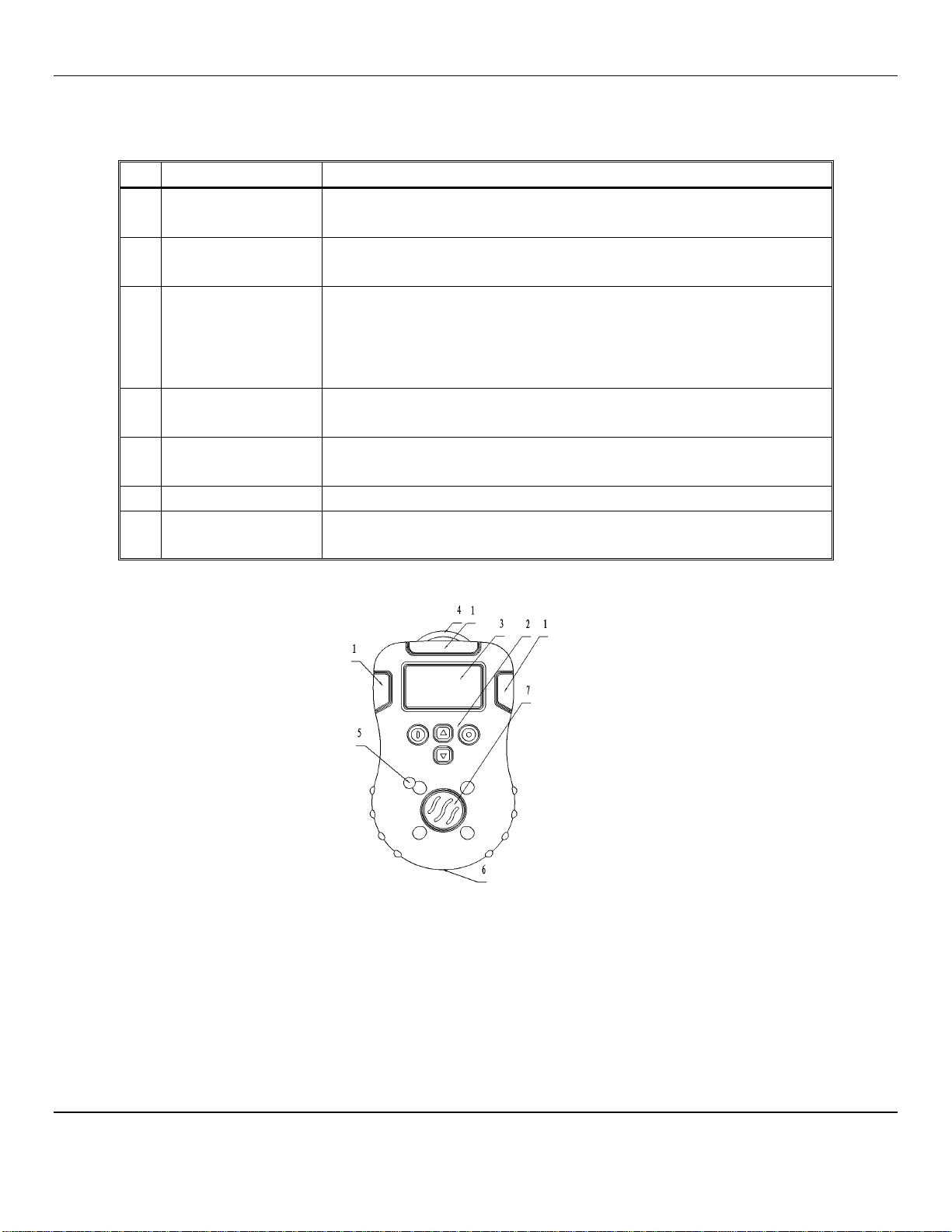
See Figure 1 for location of features:
F
EATURE
1 Visual Alarms
2 Pushbuttons
3 Display
4 Belt Clip
5 Audio Alarm
6 Charging Socket
7 Sensor
D
ESCRIPTION
Red indicators clearly visible on 3 sides and located at the top of the RECON
LED’s activate when alarm thresholds are exceeded
P
OWER
See section 3.1 for description of each pushbutton
The Liquid Crystal Display(LCD) allows messages to be read clearly:
• 4 digits (7 segments), for displaying the measurement
• pictograms symbols used to indicate supplementing the audio and visual
alarms relating to the exceeding of thresholds, battery faults, maintenance
mode etc…
Clip to outside of clothing for hands-free operation
Attached to back of the instrument
Loud buzzer located on the front of the instrument
The audio alarm (Buzzer) is on when the unit is in alarm.
Battery Charging Connection, to plug in battery charger
Located in front of the RECON
• Type varies depending on the target gas
, UP, SET and D
OWN
Buttons
Front View
Figure 1: RECON Features
2
Page 5

R
LCD,
N
F
P
F
ECON
ENMET Corporation
DISPLAY
UMBER
UNCTION
1 Battery
2 Lock
3 sound
4 vibration
5 Alarming conditions
6 Warning or the maximum level
7 numeric value
8 Error
9
Not Used
10 Clock
11 Zero calibration
12 Calibration point or calibration status
13
Not Used
14 Set-up of the parameters
15 Indication of the gas concentration units
Figure 2: RECON Display
3.0 Description of Pushbuttons
USHBUTTON
P
OWER
UP
D
OWN
SET
Activate / deactive the instrument, press and hold it for 3 seconds
Maintenance operations, See section 4
Cancel an operation
Increase the display value
Check the instrument status the LCD will display Temp. °C, time, STEL
& TWA levels, maxium level, see section 4
Set up the instrument parameters, see section 4
Decrease the display value
Maintenance operations, See section 4
Confirmation of the parameters set-up
Maintenance operations, See section 4
UNCTION DESCRIPTION
3
Page 6

R
Year
Month & Date
Hour & minute
L-alarm
H-alarm
STEL
TWA
ECON
ENMET Corporation
4.0 Operation
4.1 Activation of the RECON
To activate the detector, press the P
The detector begins a self test sequence, example listed below
1
Display Test The LCD displays all of the screen elements.
OWER
button and hold for 3 seconds.
2
Alarm Function Test
3
Indication of Version
The audio alarm beeps, the visual alarm flashes the backlight
activates briefly and the detector emits one vibration
Displays software version
4
Date and Time
Displays the date and time automatically in the following order:
Year, Month & Date, Hour & Minute
5
Indication of Alarm settings
Displays Low Alarm level then High Alarm level
Example: CO
6
Indication of STEL and TWA
For toxic instruments only
Displays STEL then TWA levels
for toxic instruments only
Example: CO
7
Warm Up Count Down
If detector passes the self-test, it enters a short warm up count
down.
3 – 30 seconds, depending on type of gas sensors installed.
Then displays ambient gas reading.
Example: CO in clean air
Proper operation of the RECON requires that the instrument be zeroed. With the RECON ON and in clean air, the display
should read 0 or 20.9 for oxygen units. See Section 4.6.
4.2 Deactivation of the RECON
To deactivate the RECON, press the P
The RECON will “beep” and display:
OWER
button and hold for 3 seconds.
4
Page 7

R
D
F
ECON
ENMET Corporation
4.3 Checking RECON Status
To activate the detector, press the P
When the RECON has finished its start up sequence. Press UP and SET buttons at the same time, the display will
indicate Temp., time, STEL & TWA levels(for toxic) and maximum level
OWER
button and hold for 3 seconds.
4.4 RECON Operational Perimeters
In this menu, you can adjust: Time, Date, Change instrument password, Activate/Deactivate the audio associated with the
pushbuttons switches and Activate/Deactivate the vibratory alarm.
With the RECON activated, press and hold the UP and D
RECON menu options press the D
ISPLAY
UNCTION
OWN
button to scroll through the option.
Press SET button to select
date and time adjustment
C
AUTION
: If you change the
password for the factory set
password 1270, record your new
password for future reference.
Press SET button to select
the Change Password option.
Press the SET button and
enter the new password.
OWN
buttons at the same time until the display
Use the UP and D
OWN
buttons to adjust display
and SET button to accept and advance to next option
Will be displayed. Then press SET button.
Will be displayed. Enter the Old password.
When the correct Old password is entered,
will be displayed.
Then enter the new password.
When the last digit is entered,
Use the UP and D
buttons to incroment digit.
Use SET button to accept
OWN
When the completed password is entered, the display will
show the date information.
digit and advance the cursor.
Not Used
Press SET button to select
Sound ON or OFF
Does Not affect Alarm Audio
Press SET button to select
Vibration ON or OFF
To exit with out saving the option state change, press the P
N
OTE
: using the UP button reverses the menu.
Press SET button to accept display indication or Use
the UP button to change. Then press SET button.
Press SET button to accept display indication or Use
the UP button to change. Then press SET button.
OWER
5
will be displayed. Re-enter the new password.
button.
Page 8

R
ECON
ENMET Corporation
4.5 Alarms
When alarming continuously, you can press SET button to turn off the audible alarm and vibration
when the and are flashing.
The following table describes RECON alarms and shows examples of display for each alarm.
Alarm Type Display
Low Alarm
Slow tone
Flash
Vibration x
High Alarm
Fast tone
Flash
Vibration x
High concentration protection y
Slow tone
Flash
Sensor Fault
Fast tone
STEL alarm
Slow tone
Flash
Vibration x
TWA alarm
Slow tone
Flash
Vibration x
Over F. S. alarm
Slow tone
Flash
6
Page 9

R
ECON
ENMET Corporation
Time error
In this condition, the device will try to renovate it
by itself. If succeeded, after start-up, it enters into
the menu of time set up. Please set up the time
according to the local time. If failed, the device
will turn off. Please contact the supplier for repair.
Memorizer error
When detecting, the device will try to renovate it
by itself. If failed, it will turn off. Please contact
the supplier for repair.
Low voltage
Modified tone alarming sound per second
If the serious low voltage, the icon will flicker.
Then the device can continue to work for 15
min at most. Please recharge it at a safe place,
otherwise it will turn off.
N
OTES:
x If vibration option is On - y For Combustible gas
4.6 Automatic Zero Calibration
In clean air, if detecting value is not 0, choose this function to make the zero calibration.
With RECON On, press both D
Press both D
After 1 second, it advances to the next status
When 0000 is displayed:
Enter the password, factory set to 1270, by using the UP button to
increment the digit and the SET button to accept the indicated digit
and move the cursor. When the correct password is entered, the display
will advance.
N
OTE
When display is stable. Press SET button to confirm the operation.
N
OTE
N
OTE
: Not applicable for oxygen instruments.
OWN
: Incorrect password will exit auto zero menu.
: the display may not indicate 0 prior to confirmation.
OWN
and SET buttons.
and SET buttons for 1 second.
S
TATUS
E
XAMPLE OF DISPLAY
7
Page 10

R
ECON
ENMET Corporation
5.0 Maintenance of the RECON
To maintain proper battery function and life the Recon should be operated once a week for 6 to 8 hours and then placed on
charge see Section 5.3
The RECON maintenacne section allows access to Zero, Calibration, Calibration target gas and alarm point adjustment menus.
To enter the maintenance menus section you must start with the instrument OFF.
W
ARNING
5.1 Calibration of the RECON
: As all the parameters of this mode may endanger the safety of the operator, so please perform the operation carefully
With the instrument OFF, press P
OWER
amd SET buttons and
hold for 5 seconds, the RECON begins a self-test. If the self-test passes,
then after a short time, it indicates request for password.
Enter the password, factory set to 1270, by using the UP button to
increment the digit and
the SET button to accept the indicated digit and move the cursor.
Only when the correct password is entered can the detector enter the maintenance menu.
If there is no operation or the password is wrong, the detector will be deactivated. So, please input the correct password in time.
5.1.2 Zero calibration
W
ARNING
N
: This operation should be carried out in the clean air. Otherwise the accuracy of the detector will be affected. When
entering into the next mode, if the displays shows E, the air is not clean, or the sensor is destroyed. choose another calibration
location or replace the sensor.
OTE
: Not used with Recon Oxygen units
At this time, if SET button is pressed or no operation within 1 minute, the
RECON will accept the present concentration as the zero point, and then enters
into the mode of calibration point set up.
Connect the calibration cover to the instrument, attach the regulator to the gas
cylinder.
To Exit press P
P
OWER
OWER
button, menu will bypass the calibration step to enter into the mode of alarming level set up, press
button advance and exit.
8
Page 11

R
RECON
ECON
ENMET Corporation
5.1.3 Calibration Point Adjustment
In this mode, display is the last concentration of gas used to calibrate the
instrument. Press UP or Down button to modify the display.
N
OTE
: Not used with Recon Oxygen units
N
OTE
: 20.9% Oxygen is the only calibration level to be used with Recon Oxygen units
Press the SET button to accept the level or within 1 minute, the RECON
will accept the present concentration as the calibration gas concentration.
The display will change to 0..
Open the valve on the regulator
Within 30 seconds, if the RECON detects the calibration gas, it will start up the
calibration date analysis procedure by itself. Continue gas flow.
In 2 to 3 minutes the
arithmetics to complete the gas response process. Then the RECON saves the
best arithmetics to complete calibration.
W
ARNING
:
The RECON must self calibrate, please avoid touching any
buttons, otherwise the accuracy will be effected badly.
will automatically adjust the conversion
After that it enters into the L-alarm set up. Press P
OWER
button twice to
advance and exit.
If the RECON can not reach half the calibration figure within 30 seconds, or the gas concentration is outside the maximum
drift range of the sensor, the E icon will light and 0000 will be displayed. This means the gas is not proper for calibration or the
sensor is depleted.
Verify calibration gas is correct. If correct retry calibration sequence. If failure occurs sensor may need to be replaced.
Remove calibration cover from instrument.
To exit calibration menu.
Press SET button 3 times and then the P
OWER
button 4 times.
Press the SET button then
Press P
OWER
button
9
Page 12

R
Low Alarm
High Alarm
ECON
ENMET Corporation
5.2 Alarm Levels Adjustment of the RECON
5.2.1 Set up of L-alarm (Low Alarm)
With the RECON Off press and hold the P
OWER
and SET buttons until unit activates.
When 0000 is displayed, enter the password, factory set to 1270, by using the UP button to increment the digit and the SET
button to accept the indicated digit and move the cursor. When the correct password is entered, the display will advance.
Press the P
OWER
button to advance to alarm set menu.
In this mode, the L-alarm level can be adjusted. Press UP or Down button to adjust the flickering figure according to
your need, and then press SET button to complete the set up. After that, it enters the H-alarm set up.
N
OTE
: The display will not allow an unacceptable alarm level.
5.2.2 Set up of H-alarm (High Alarm)
01In this mode, the H-alarm level can be adjusted. Press UP or Down button to adjust the flickering figure according
to your need, and then press SET to complete the set up. After that the detector will automatically turn off.
N
OTE
: The display will not allow an unacceptable alarm level.
5.3 Battery Charging
When the battery voltage is low, the RECON will not function properly. To recharge the batteries of the RECON: The
RECON must be Off, connect the AC connector plugs of the charger to a 110VAC or 220VAC outlet and plug the charging
cable into the RECON. The detector will activate automatically and indicates that it is being charged. When the charging
cycle is completed, the display will indicate full charge.
W
ARNING
:
DO NOT start the battery
charge process with the RECON power on; otherwise the charge speed will be
adversely affected. Always charge the battery in normal ambient air. Do not charge the RECON in a hazardous
area to be monitored, to avoid fire or explosion. Disconnect the charger after 24 hours, failure to do so will
damage the battery.
Typical expected battery life and time to recharge:
RECON for CO, H2S, O2 30+ Hours, non-alarm condition: Recharge time: approximately 4 – 6 hours
RECON for %LEL CH4 8 hours, non-alarm condition: Recharge time: approximately 6 hours
N
OTE
: To maintain proper battery function and life the Recon should be operated once a week for 6 to 8 hours and then placed
on charge.
5.4 Sensor Replacement
Sensor life in the RECON is typically: 2 years for Carbon Monoxide & Hydrogen Sulfide and 1year for Oxygen and
Combustible.
The sensor needs to be replaced when the RECON can no longer be calibrated or if the sensor becomes erratic.
Contact ENMET for sensor replacement information.
Table1: RECON Factory Set Parameters
Model Gas Range
R
ECON
/EX Methane 0-100%LEL 10%LEL 50%LEL 10%LEL – 25%LEL 25%LEL – 80%LEL N/A N/A 50%LEL
R
ECON
/HS Hydrogen Sulfide 0-100ppm 10ppm 15ppm 5ppm – 15ppm 15ppm – 30ppm 10ppm 15ppm 40ppm
R
ECON
/CO Carbon Monoxide 0-1000ppm 35ppm 100ppm 25ppm – 100ppm 100ppm – 500ppm 25ppm 200ppm 500ppm
R
ECON
/O2 Oxygen 0-30%vol 19.5%vol 23.5%vol 16%vol – 19.5%vol 22.5%vol – 24%vol N/A N/A 20.9%
Low Alarm Range High Alarm Range TWA STEL Cal Gas
10
Page 13

R
M
P
S
2.
ECON
ENMET Corporation
6.0 Specifications and Troubleshooting Tips
6.1 Specifications
Electrical Power Working Voltage
Operation Temperature:
Mechanical Dimensions:
N
OTE
: All specifications stated in this manual may change without notice.
Working time continuous, non-alarm conditions
Charge time 4 to 6 hours
Relative Humidity
Weight:
Ingress Protection IP 65
Approval Designed to be intrinsically safe
6.2 Troubleshooting Tips
ALFUNCTION
Unable to Turn on the detector
No reaction to the tested gas
Inaccurate indication
Wrong time display
OSSIBLE REASONS
low voltage Charge Battery
Detector Fault Contact ENMET Corporation
Circuit malfunction Contact ENMET Corporation
Exhausted Sensor Replace Sensor
Circuit malfunction Contact ENMET Corporation
Exhausted sensor Replace the sensor
Overdue Calibration Calibrate
Exhausted battery Charge and reset the time
Electromagnetic disturb Reset the time
3.6VDC Lithium battery,1200 mAh Rechargeable
Combustible gas: Approximately 8 hours
Toxic gas: Approximately 30+ hours
–20°C to +50°C
5 to 95% RH, non-condensing
2.4 x 3.9 x 1.3 inches(60 x 100 x 33 mm)
5 oz. (140g) including battery
OLUTIONS
Zero calibration function failed Too much drift Calibrate or replace the sensor
7.0 Accessories Parts
Recon is supplied with a belt clip(4) and an alligator-type clip(1) with a D-ring(2). These can be attached to the instrument as
shown below.
1.
Alligator-Type Clip
D-Ring
3.
Fastening Screw
4.
Belt Clip
Attached
010101Belt Clip & Alligator Type Clip Attached Alligator-Type Clip
11
Page 14

R
ECON
ENMET Corporation
8.0 WARRANTY
ENMET warrants new instruments to be free from defects in workmanship and material under normal use for a period of one
year from date of shipment from ENMET. The warranty covers both parts and labor excluding instrument calibration and
expendable parts such as calibration gas, filters, batteries, etc... Equipment believed to be defective should be returned to
ENMET within the warranty period (transportation prepaid) for inspection. If the evaluation by ENMET confirms that the
product is defective, it will be repaired or replaced at no charge, within the stated limitations, and returned prepaid to any
location in the United States by the most economical means, e.g. Surface UPS/FedEx Ground. If an expedient means of
transportation is requested during the warranty period, the customer is responsible for the difference between the most
economical means and the expedient mode. ENMET shall not be liable for any loss or damage caused by the improper use of
the product. The purchaser indemnifies and saves harmless the company with respect to any loss or damages that may arise
through the use by the purchaser or others of this equipment.
This warranty is expressly given in lieu of all other warranties, either expressed or implied, including that of merchantability,
and all other obligations or liabilities of ENMET, which may arise in connection with this equipment. ENMET neither
assumes nor authorizes any representative or other person to assume for it any obligation or liability other than that, which is set
forth herein.
NOTE: When returning an instrument to the factory for service:
Be sure to include paperwork.
A purchase order, return address and telephone number will assist in the expedient repair and return of your unit.
Include any specific instructions.
For warranty service, include date of purchase
If you require an estimate, please contact ENMET Corporation.
There are Return for Repair Instructions and Form on the last pages of this manual. This Form can be copied or used as needed.
Manual Part Number
80006-018
April, 2008
MCN-405, 07/18/08
MCN-410, 12/03/08
MCN-415, 04/02/09
MCN-430, 04/13/10
MCN-440, 08/23/10
Notes:
12
Page 15

PO Box 979
680 Fairfield Court
Ann Arbor, Michigan 48106-0979
734.761.1270 Fax 734.761.3220
Returning an Instrument for Repair
ENMET instruments may be returned to the factory or any one of our Field Service Centers for regular repair
service or calibration. The ENMET Repair Department and Field Service Centers also perform warranty
service work.
When returning an instrument to the factory or service center for service, paperwork must be included which
contains the following information:
A purchase order number or reference number.
A contact name with return address, telephone and fax numbers
Specific instructions regarding desired service or description
of the problems being encountered.
Date of original purchase and copy of packing slip or invoice
for warranty consideration.
If a price estimate is required, please note it accordingly and be
sure to include a fax number.
Providing the above information assists in the expedient repair and return of your unit.
Failure to provide this information can result in processing delays.
ENMET charges a one hour minimum billing for all approved repairs with additional time billed to the closest
tenth of an hour. All instruments sent to ENMET are subject to a minimum evaluation fee, even if returned
unrepaired. Unclaimed instruments that ENMET has received without appropriate paperwork or attempts to
advise repair costs that have been unanswered, after a period of 60 days, may be disposed of or returned
unrepaired COD with the evaluation fee.
Service centers may have different rates or terms. Be sure to contact them for this information.
Repaired instruments are returned by UPS/FedEx Ground and are not insured unless otherwise
specified. If expedited shipping methods or insurance is required, it must be stated in your paperwork.
Note: Warranty of customer installed components.
If a component is purchased and installed in the field, and fails within the warranty term, it can be
returned to ENMET and will be replaced, free of charge, per ENMET’s returned goods procedure.
If the entire instrument is returned to ENMET Corporation with the defective item installed, the item will
be replaced at no cost, but the instrument will be subject to labor charges at half of the standard rate.
Page 16

Mailing
Address:
Shipping Address:
Repair Return Form
ENMET Corporation
PO Box 979
Ann Arbor, Michigan 48106
Phone Number: 734.761.1270
FAX Number: 734.761.3220
Your Mailing Address:
Contact Name: __________________________ Your Phone: _______________________
Your PO/Reference Number: _______________ Your FAX: _______________________
ENMET Corporation
Attn: Repair Department
680 Fairfield Court
Ann Arbor, Michigan 48108
Your Shipping Address:
Payment Terms: K COD
(Check one) K VISA / MasterCard______________________ ________ ________
Card number Expiration Card Code
K American Express______________________ ________ ________
Card number Expiration Card Code
Name as it appears on the credit card___________________________________
Return Shipping Method:
K UPS: K Ground K 3 Day Select K Next Day Air K ND Air Saver K 2-Day Air
K UPS Account number: ________________________
K Federal Express: K Ground K Express Saver K P-1 K Standard K 2-Day Air
K FedEx Account number: ________________________
Would you like ENMET to insure the return shipment?
K No K Yes Insurance Amount: $_________________
 Loading...