

Page 1

ENMET Corporation
PO Box 979
Ann Arbor, MI 48106-0979
www.enmet.com
Operation and Maintenance
PGD2
Manual
Manual Part Number
80006-020
MCN-13-001, 04/04/13
Page 2

CONTENTS
1 WARNING NOTICES ..................................................................................................................................................................... 1
1.1 S
1.2 B
1.3 E
1.4 B
1.5 D
1.6 E
1.7 R
ENSOR “POISONING
ATTERY CHARGING, CALIBRATION & TESTING
LECTROSTATIC HAZARD
ATTERY DISPOSAL
ISPOSAL OF GAS SENSORS
LECTROMAGNETIC COMPATIBILITY
APID READING CHANGES
” ................................................................................................................................................................. 1
........................................................................................................................................................... 1
.................................................................................................................................................................... 1
........................................................................................................................................................ 1
........................................................................................................................................... 1
.......................................................................................................................................................... 1
......................................................................................................................... 1
2 CERTIFICATION DATA ............................................................................................................................................................... 1
2.1 S
PECIAL CONDITIONS FOR SAFE USE
........................................................................................................................................... 1
3 DEFINITIONS AND ABBREVIATIONS ..................................................................................................................................... 2
4 PGD2 FEATURES AT A GLANCE ............................................................................................................................................... 2
5 INTRODUCTION ............................................................................................................................................................................ 3
5.1 S
5.2 G
PECIFICATION
ENERAL DESCRIPTION
............................................................................................................................................................................ 3
.............................................................................................................................................................. 4
6 OPERATING INSTRUCTIONS .................................................................................................................................................... 6
6.1 S
6.2 S
6.3 P
6.4 S
6.5 M
6.6 D
6.7 A
6.8 C
6.9 STEL
6.10 A
6.11 F
6.12 S
6.13 PGD S
6.14 A
6.15 L
6.16 D
6.17 S
6.18 EXP / LEL / VOL
6.19 C
6.20 U
6.21 D
6.22 O
6.23 F
6.24 A
WITCHING ON
WITCHING OFF
EAK READINGS MODE
ENTINEL WORKING MODE
ENU FACILITIES
ATE / TIME
DJUST SOUNDER
ALIBRATION DUE DATE
AND
LARM LEVELS
LAMMABLE DISPLAY
ET
LCD C
ERIAL NO
LARM ACCEPT
OW BATTERY ALARM
ISPLAY BACKLIGHT
ENSOR ZERO
ONFIDENCE BLEEP
SER IDENTIFICATION
ATA LOGGING
VERRANGE INDICATION
AULT INDICATION
SPIRATION
............................................................................................................................................................................ 7
........................................................................................................................................................................... 7
............................................................................................................................................................... 7
........................................................................................................................................................................ 8
............................................................................................................................................................................... 8
....................................................................................................................................................................... 8
TWA V
ALUES
........................................................................................................................................................................ 10
............................................................................................................................................................... 11
ONTRAST
................................................................................................................................................................. 12
. ...................................................................................................................................................................... 12
........................................................................................................................................................................ 12
............................................................................................................................................................. 12
................................................................................................................................................................ 12
........................................................................................................................................................................... 13
DISPLAY OPTIONS
.................................................................................................................................................................. 13
............................................................................................................................................................... 13
......................................................................................................................................................................... 14
................................................................................................................................................................... 15
.............................................................................................................................................................................. 15
.......................................................................................................................................................... 7
............................................................................................................................................................ 8
........................................................................................................................................................... 9
....................................................................................................................................... 13
.......................................................................................................................................................... 15
7 PUMPED INSTRUMENTS .......................................................................................................................................................... 16
7.1 P
7.2 P
UMP OPERATION
UMP BLOCKAGE
..................................................................................................................................................................... 16
...................................................................................................................................................................... 16
8 CALIBRATION ............................................................................................................................................................................. 17
8.1 C
8.2 K
8.3 E
ALIBRATION
EYPAD CALIBRATION PROCEDURE
XAMPLES OF STANDARD
............................................................................................................................................................................ 17
ENMET C
......................................................................................................................................... 17
ALIBRATION GAS & ACCESSORIES
................................................................................... 19
9 BATTERY CHARGING EQUIPMENT ...................................................................................................................................... 19
Page 3

9.1 C
9.2 5-W
9.3 V
9.4 C
9.5 B
OMPACT CHARGER TYPE
AY CHARGER TYPE
EHICLE-MOUNTED CHARGER TYPE
HARGER TYPE
ATTERY MODULE CHARGING
PGDC2, PGDC2/I .......................................................................................................................................... 20
PGDC4 .......................................................................................................................................... 20
PGDC5 ............................................................................................................................................... 20
................................................................................................................................................. 20
PGDC3 .......................................................................................................................... 20
10 BATTERY REPLACEMENT .................................................................................................................................................. 20
11 HAZARDOUS AREA USE ....................................................................................................................................................... 21
11.1 A
11.2 M
11.3 B
11.4 C
12 SENSORS ................................................................................................................................................................................... 22
12.1 F
12.2 T
12.3 O
13 CALIBRATION, CONFIGURATION & PROGRAMMING ............................................................................................... 27
REAS OF USE
ETHODS OF USE
ASIC PRECAUTIONS
ONFINED SPACE PRE-ENTRY CHECKS
LAMMABLE SENSORS
12.1.1 LEL Flammable Sensors .................................................................................................................................................. 22
12.1.2 0 - 100% Volume Flammable Sensors ............................................................................................................................. 23
OXIC SENSORS
12.2.1 Cross Sensitivity ............................................................................................................................................................... 24
12.2.2 Temperature Dependence ................................................................................................................................................ 24
12.2.3 Stabilization ..................................................................................................................................................................... 24
12.2.4 Toxic Sensor Types and Characteristics .......................................................................................................................... 25
XYGEN SENSORS
12.3.1 Cross Sensitivity ............................................................................................................................................................... 26
12.3.2 Temperature ..................................................................................................................................................................... 26
12.3.3 Pressure Transients .......................................................................................................................................................... 26
12.3.4 Humidity ........................................................................................................................................................................... 26
12.3.5 Oxygen Sensor Types and Characteristics ....................................................................................................................... 26
........................................................................................................................................................................... 21
...................................................................................................................................................................... 21
................................................................................................................................................................. 21
..................................................................................................................................... 21
.............................................................................................................................................................. 22
........................................................................................................................................................................ 24
.................................................................................................................................................................... 26
13.1 PC I
13.2 C
13.3 C
13.4 P
14 TROUBLESHOOTING ............................................................................................................................................................ 28
15 WARRANTY .............................................................................................................................................................................. 29
NTERFACING (USING OPTIONAL ACCESSORIES
ALIBRATION
ONFIGURATION (USING OPTIONAL SOFTWARE & HARDWARE
ROGRAMMING (USING OPTIONAL SOFTWARE & HARDWARE
............................................................................................................................................................................ 27
).................................................................................................................. 27
) ............................................................................................... 27
) ................................................................................................. 27
Page 4

ENMET Corporation PGD2
1 W
ARNING NOTICES
1.1 Sensor “Poisoning”
Silicone based lubricants, corrosion inhibitors and water repellents must not be used in close proximity to the sensors. Such
compounds may poison the flammable sensors (pellistors) resulting in a loss of sensitivity.
This poisoning effect is common to all catalytic sensors.
1.2 Battery Charging, Calibration & Testing
Equipment used for charging, calibration and testing of the Portable Gas Detector must be located outside a hazardous area i.e. in an
atmosphere where it is known that there is no risk of the presence of combustible gas.
1.3 Electrostatic Hazard
The blue plastic instrument case and red lens must only be cleaned in a safe area.
1.4 Battery Disposal
Rechargeable battery packs or individual cells must be disposed of via an appropriate battery recycling scheme.
1.5 Disposal of Gas Sensors
The toxic and oxygen sensors used in the PGD2 contain toxic compounds. They should be disposed of according to local waste
management requirements and environmental legislation. They should not be burnt since they may emit toxic fumes.
Flammable sensors do not represent a hazard.
1.6 Electromagnetic Compatibility
The PGD2 Portable Gas Detector and associated equipment complies with the current European standards for both electromagnetic
emissions and immunity. However, this does not imply that the apparatus will be immune from interference under all operational
conditions and may exhibit temporary instability if exposed to high levels of interference for example, when in very close proximity to a
mobile phone transmission.
1.7 Rapid Reading Changes
FLAMMABLE INSTRUMENTS ONLY
CAUTION: ANY RAPID UP-SCALE READING FOLLOWED
BY A DECLINING OR ERRATIC READING MAY INDICATE
A GAS CONCENTRATION BEYOND UPPER SCALE LIMIT
WHICH MAY BE HAZARDOUS.
2 C
The Portable Gas Detector Model PGD2 is Baseefa ATEX certified for use in Group IIC potentially explosive atmospheres under the
following certificate number: Certificate No. Baseefa 03ATEX0235X
ERTIFICATION DATA
2.1 Special Conditions for Safe Use
The above certificate specifies the following conditions for safe use:-
1. The rechargeable battery pack Type PGD/BATT may only be recharged in the safe area.
2. The enclosure is manufactured from plastic and has a surface resistivity of greater that 1 Gohm and therefore poses a risk
from electrostatic ignition. The rubber boot is to be fitted to the apparatus. By virtue of its shape and design, the apparatus is
not considered to be an electrostatic risk; however, the apparatus must not be installed in a position where it may be
subjected to an excessive air/fluid flow or be subjected to rubbing that may cause an electrostatic build-up.
3. The apparatus is not designed for use in oxygen enriched atmospheres i.e. greater than 21% oxygen.
1
Page 5

ENMET Corporation PGD2
3 D
Aspirator
Data Logging
EXP
LEL
%LEL
TWA
PC
Pellistors
PGD2
PPM
STEL
T90 Response Time
EFINITIONS AND ABBREVIATIONS
A hand operated pump attachment which enables gas to be drawn into the instrument.
The automatic recording of readings stored in the solid state memory of the instrument
for later retrieval.
Explosive Gas.
Lower Explosive Limit, the volume ratio of flammable gas or vapor in air below which an
explosive gas atmosphere will not be formed.
The percentage of the Lower Explosive Limit
e.g. the LEL for methane is 5% volume in air, therefore 20% LEL is equivalent to 1%
volume in air (i.e. 20% of 5% volume)
Time-Weighted-Average, taken over an 8 hour reference period.
Also referred to as LTEL, Long Term Exposure Limit
A ‘personal computer’ based on the original IBM standard.
Devices used for the detection of a wide range of flammable gases normally comprising
of individual detector and compensator ‘bead’ elements operating on the principle of
catalytic oxidation.
Portable Gas Detector - 2nd generation, monitoring up to 4 gases.
Parts per Million.
Short Term Exposure Limit, the average exposure over a 15 minute sampling period.
The time taken to reach 90% of the true value
4 PGD2 F
♦ Monitoring of up to 4 gases
♦ Pumped versions available
♦ Sensors can be added or removed after purchase
♦ Robust construction - high impact resistance
♦ Data Logging in 3 modes
♦ STEL and TWA monitoring
♦ Flammable gas selection from built -in menu
♦ Peak readings facility for pre - entry testing
♦ Sentinel working mode
♦ Displays in scientific units
♦ Programmable alarm levels for each sensor
♦ Audible and visual alarms
♦ Sensor zero function
♦ Fully reprogrammable without removal from protective case
♦ Serial number and calibration due dates stored within instrument
♦ Display contrast adjustable via instrument menu
♦ Audible alarm level adjustable via instrument menu
♦ Display backlighting
♦ Power and Fault indicators
♦ Low battery alarm
♦ Choice of mains powered or vehicle powered chargers
♦ Calibration via a PC using specially designed Windows software
♦ Extensive software support
♦ Accessories to provide aspiration
♦ Protective rubber case and body harness
EATURES AT A GLANCE
2
Page 6

ENMET Corporation PGD2
5 I
NTRODUCTION
This Instruction Manual No.1 provides information on the General Operation of the PGD2 instrument.
Instruction Manual No.2 The Data Processing-Calibration-Configuration & Programming of the PGD2 provides information on the use
of the specially designed Windows based software package available for use with the instrument.
5.1 Specification
Size
Weight
No. of Gases
Gas Types
Internal Pump
Power Sources
Minimum operating times
Visual indications
Audible indication
Alarm levels
Data Logging Modes
Display formats
Controls
Temperature range
Environmental Rating
Humidity range
Electromagnetic compatibility
Air Pressure Operating Range
185mm high x 108mm wide x 50mm deep.(excluding boot)
1Kg.
Up to four.
Flammable, Toxic, Oxygen (See section 12 for sensor specifications).
Available to order (suffix P).
3.5 Volts dc.
i). rechargeable battery pack Model PGD/BATT.
12 hours.
i). 2 x 16 character LCD display with backlight.
ii). large flashing red lens section used to indicate alarm conditions.
iii). Green ‘Power’ and amber ‘Fault’ indicators in lens.
Electromagnetic alarm in red lens section.
Flammable : single level instant alarm.
Toxic (each sensor) : 3 levels - instant, STEL, TWA.
Oxygen : 2 levels - instant low, instant high.
Automatic calculation of STEL and TWA readings.
i). Automatic variable rate according to gas levels.
ii). Fixed rate.
iii). Fixed fast rate.
iv). Off.
ppm, %, LEL.
i). Front panel - on/off, right arrow, left arrow, on/off/menu.
ii). Top panel - display backlight, alarm mute.
i). operating -5 to + 40
ii). storage -20 to + 50
IP66.
15% to 95% relative humidity, non-condensing. Operation is possible in
the range 0-100% R.H. however, sensor life will be reduced by
continuous operation at extremes of humidity and temperature.
CE Marked, Tested to EN50081-2, EN50082-1, EN55022 (Limit B).
920 mbar to 1150 mbar.
O
O
C.
C.
3
Page 7
ENMET Corporation PGD2
5.2 General Description
The PGD2 is an intrinsically safe portable multi-gas instrument for use in Group IIC potentially explosive atmospheres. The instrument
is intended to be used for the protection of personnel entering or working in an environment where a gas hazard may, or is known to
exist.
The instrument produces both an audible and visual alarms if any of the monitored gas levels fall outside pre-set limits.
It can be fitted with up to 4 gas sensors in various combinations of flammable, toxic and oxygen to provide simultaneous monitoring of
each gas. The data logging facilities available within the instrument allow the exposure levels for each gas to be stored for
downloading to a personal computer at the end of the work period. The instrument also automatically calculates the STEL and TWA
values.
Pumped versions are available at additional cost.
Note: The Model PGD3-IR Portable Gas Detector is also available. This instrument uses the latest technology miniature
infrared gas sensors for the detection of a wide range of hydrocarbon gases and carbon dioxide. Infrared gas sensors offer
several advantages including immunity to ‘poisoning’, fail-safe operation and a longer operating life.
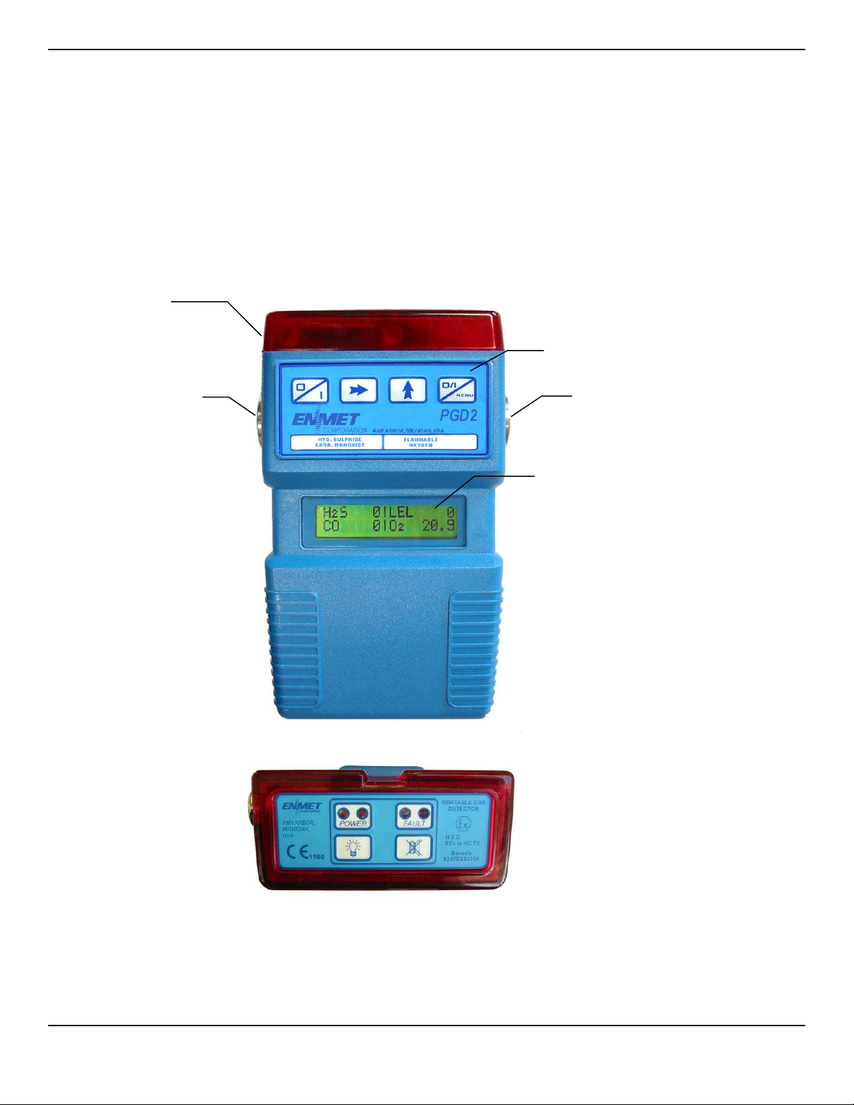
Lens
Gas Inlet
Front Panel
Keypad
Gas Inlet
LCD Display
Figure 1 - Front View of Portable Gas Detector with Case Removed
Figure 2 - Top View Showing Lens Keypad and Certification Data
4
Page 8
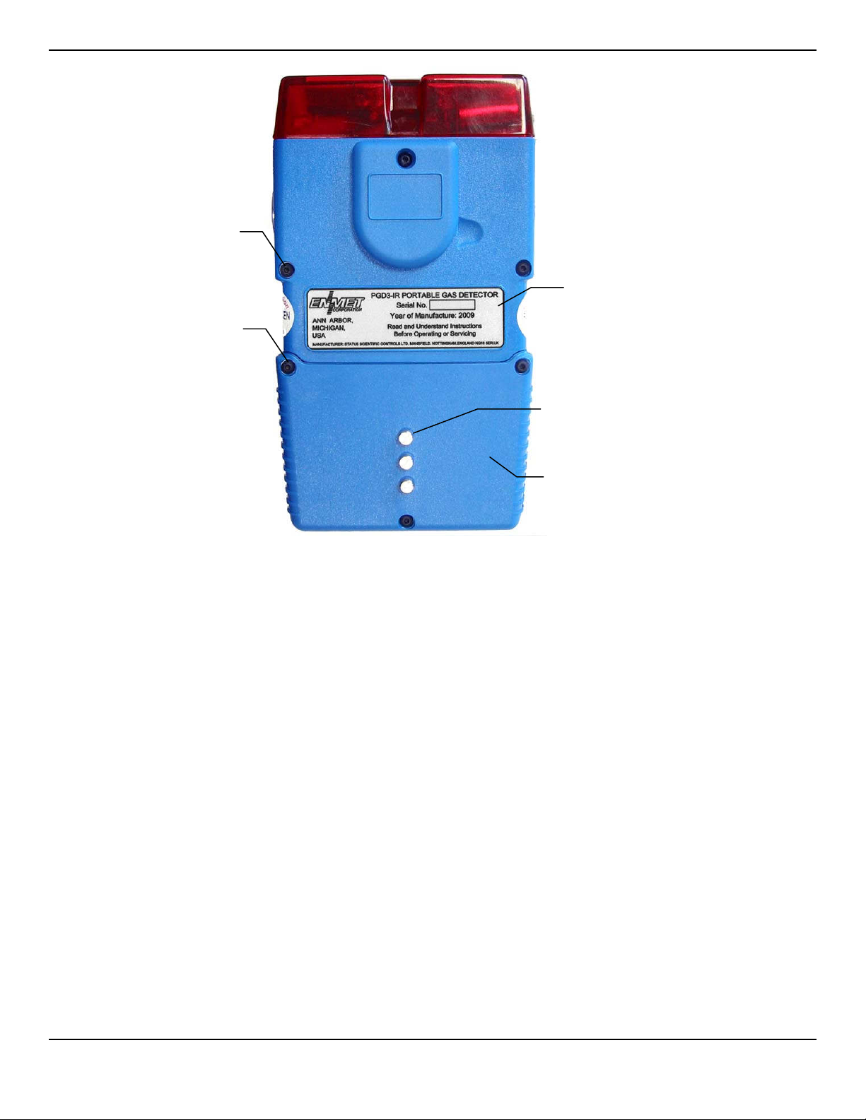
ENMET Corporation PGD2
Battery Pack
Rear Cover Retaining
Screws –
3 Positions
Battery Retaining
Screws –
3 Positions
Nameplate with
Serial Number
Charging Pins
Rechargeable
Figure 3 - Rear View of Rechargeable
Portable Gas Detector with Case Removed
Reference to Figures 1 to 3 shows that the instrument comprises the following main parts: -
• The main instrument case moulded in high impact resistance “Bayblend” internally coated to provide electromagnetic shielding. A
belt clip and suspension hook may be optionally fitted during manufacture.
• A removable battery pack.
• A large red lens section containing flashing led indications, audible alarm and infra-red communications link.
• Gas sensors and control electronics (contained in anti-impact mountings) housed within the main instrument case section.
• A two line by 16-character liquid crystal display with backlight.
• A four-key membrane type front panel control switch, large enough to be operated by a gloved hand.
• A two-key membrane type top panel control switch. This membrane also carries the power and fault indicators and certification
data.
• Gas sensor inlets which are separately sealed to help prevent water ingress to the instrument electronics.
• A nameplate carrying the serial number of the instrument
The instrument is supplied fitted with a moulded rubber boot which provides good protection in hostile environments. The instrument
can be both charged and calibrated without removal from the boot. It is a condition for safe use that the boot is always fitted when
used in a potentially explosive atmosphere – see section 2.1.
A body harness is also supplied as standard and comprises shoulder and waist straps which attach to the moulded rubber boot. These
straps can also be utilised to lower the instrument during pre-entry checks.
The instrument is powered from a rechargeable battery pack. It is a condition for safe use that the battery pack may only be
recharged in a safe area – see section 2.1.
5
Page 9
ENMET Corporation PGD2
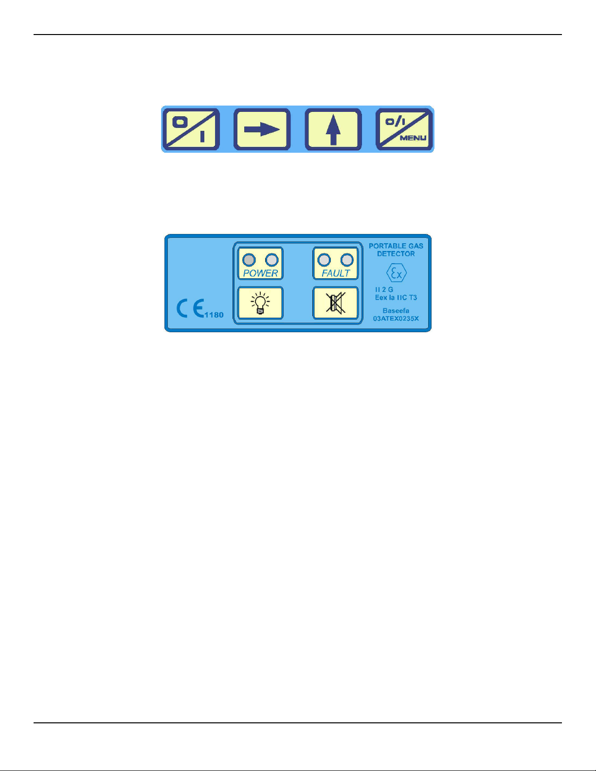
6 O
PERATING INSTRUCTIONS
A B C D
FRONT PANEL SWITCHES
TOP PANEL SWITCHES
E F
6
Page 10
ENMET Corporation PGD2
6.1 Switching on
To switch the instrument on, press buttons A and D together.
The instrument goes through a self-check cycle, check that the audible and visual alarms are operating and that the display shows the
following sequence: -
Note : Instruments fitted with PGD1 emulation code do not show PGD2
Note - The top line of this display will vary according to the software and instrument configuration.
*V=1.13 is the software version which may vary
After 2 seconds the display shows the date and time followed by the gas levels.
The gas level display shown depends upon the gas sensors fitted. A typical display for a 4-gas instrument is shown below: -
CHECKING PROGRAM
PGD2 V4.4.2PAp Da
FLAM = METHANE
DATE 10 / 04 / 07
TIME 14 : 12 : 34
H2S 0.0 ▐ LEL 0
CO 0 ▐ O2 20.9
6.2 Switching off
To switch the instrument off, press and hold buttons A and D together until the display goes off.
6.3 Peak Readings mode
The instrument can be set to measure and hold the highest flammable and toxic gas readings and the lowest oxygen reading, this
feature is particularly useful for carrying out pre-entry testing for gas. For example, by lowering the instrument into a manhole and then
withdrawing it to observe the peak readings to ensure that it is safe to enter.
To turn Peak Readings on / off, press buttons B and C together until the display reads: -
either or
PEAK READINGS ON
PEAK READINGS OFF
When Peak Readings is on, the display alternates between :typically and
H2S 0.0 ▐ LEL 0
CO 0 ▐ O2 20.9
PEAK READINGS
6.4 Sentinel working mode
Because of it’s large, 360 degree visible, red alarm top, the instrument can be suspended in a hazardous area to provide protection to
more than one person. Used in this way, all personnel in the vicinity will be able to observe the change in visual flash rate should an
alarm occur.
This method eliminates both the requirement for multi-headed devices traditionally used in the past, or for additional units in order to
achieve sentinel working.
7
Page 11

ENMET Corporation PGD2
6.5 Menu facilities
The Menu button allows the instrument to be interrogated to obtain information on any of the items listed below. These are sequentially
selected by successive operation of button D: -
DATE / TIME
ADJUST SOUNDER
CALIBRATION DUE DATE
STEL & TWA VALUES
ALARM LEVELS
FLAMMABLE DISPLAY
SET LCD CONTRAST
PGD SERIAL No.
If more details are available on a particular item then the user is prompted to press one of the arrow keys as described in the following
sections.
Note that the instrument automatically returns to the gas level display after approximately 4 seconds if the menu button or arrow button
is not operated again.
6.6 Date / Time
The current date and time are momentarily displayed when the instrument is first switched on (Section 6.1) and may also be accessed
via the menu button (Section 6.5).
Changing the date and time can only be carried out via a PGD2 Interface Unit, Interface/Charger Unit or Autocalibration Unit. Refer to
the instruction manuals for the individual items for further details.
6.7 Adjust Sounder
The frequency and hence the volume of the sounder can be adjusted via the menu button. From the menu, the user is prompted to
press the up arrow key:-
Sequential operation of the up arrow key varies the frequency/volume. Pressing the right arrow key sequentially steps the
frequency/volume in the opposite direction.
ADJUST SOUNDER
PRESS [] KEY
6.8 Calibration Due Date
The date when the instrument is due for its next calibration can be viewed via the menu button (Section 6.5).
The PGD2 can be configured via the PC configuration software(optional accessory) to either allow an instrument to be used beyond it’s
calibration due date or to prohibit further use until calibration has been carried out. Where the instrument is set to permit further use, a
warning is given each time the instrument is switched on to alert the user that calibration is required. Where it is set to prohibit further
use, then when the instrument is switched on the alarm continually sounds with the message: -
The calibration due date is updated each time an instrument is calibrated.
CALIBRATION DUE
8
Page 12

ENMET Corporation PGD2
6.9 STEL and TWA Values
The current STEL and TWA values may be viewed via the menu button (Section 6.5). These values represent the calculated Short
Term Exposure Levels (STEL) and Time Weighted Average Long (TWA)/ Term Exposure Levels (LTEL) for the toxic gases to which
the user has been most recently subjected.
From the menu, the user is prompted to press the up arrow key to view the readings: -
Sequential operation of the up arrow key shows in turn the STEL and TWA readings for toxic sensor 1 followed by those for toxic
sensor 2, for example:-
STEL
H2S 1 ppm
Readings for toxic sensor 1 – Hydrogen Sulphide
STEL
CO 23 ppm
Readings for toxic sensor 2 - Carbon Monoxide
Pressing the menu button after viewing the above displays returns the instrument to the next menu item.
COSHH VALUES
PRESS [] KEY
TWA
H2S 2 ppm
TWA
CO 34 ppm
9
Page 13

ENMET Corporation PGD2
6.10 Alarm Levels
The alarm level settings for the instrument may be viewed via the menu button (Section 6.5). These values represent the alarm setpoints which have been programmed into the instrument during calibration.
From the menu, the user is prompted to press the up arrow key to view the readings: -
Sequential operation of the up arrow key shows in turn the alarm set points for each sensor. A typical display sequence for a 4-gas
instrument would be:-
ALARM LEVELS
PRESS [ ] KEY
INSTANT ALARM
O2 LOW 19%
Alarm settings for the Oxygen sensor - two settings
INSTANT ALARM
FLAM 20 % LEL
Alarm setting for the Flammable sensor - one setting
INSTANT ALARM
H2S 15 ppm
STEL ALARM
H2S 10 ppm
Alarm settings for toxic sensor 1, Hydrogen Sulphide - three settings
INSTANT ALARM
CO 400 ppm
INSTANT ALARM
O2 HIGH 23%
or FLAM 1.00 %VOL if in the volume mode
TWA ALARM
H2S 5 ppm
STEL ALARM
CO 200 ppm
Alarm settings for toxic sensor 2, Carbon Monoxide - three settings
Important: - The Instantaneous Alarm settings must be greater than both the Short Term and Time-Weighted-Average/Long
Term exposure alarm settings. The Flammable sensor alarm setting cannot be set above 60% LEL.
TWA ALARM
CO 50 ppm
10
Page 14

ENMET Corporation PGD2
6.11 Flammable Display
Note : From software version 1.20 this facility can be disabled via the PC configuration program and may therefore be unavailable on
certain instruments.
The flammable sensor display can be programmed to show the readings for a variety of different flammable gas types, these are
selected via the menu button (Section 6.5). Selection of the appropriate gas to be monitored also automatically adjusts the calibration
factor within the instrument.
From the menu, the user is prompted to press the up arrow key to view the readings: -
Sequential operation of the up arrow key shows in turn the flammable display options e.g.: -
To select, press the right arrow key when the required gas is being displayed.
Confirmation of the selection can be made by switching the instrument off and then on and observing the display as illustrated in
Section 6.1.
A typical list of flammable gas and vapors types available through the menu is given in the table below. Additional gases may be
added using optional software upgrades. For reference, the lower explosive limit (LEL) in % by volume for each gas is listed. In some
cases there are slight differences between the accepted values of the % by volume concentrations which equal the 100% LEL of some
gases and vapors depending upon the international source of such technical data.
* The “user” option allows gases not on the above list to be configured into the instrument. This is achieved by use of the PGD2
Interface Unit option in conjunction with a PC. A calibration factor for the gas is required, contact ENMET for further information.
FLAM DISPLAY
PRESS [ ] KEY
METHANE
PRESS [ ] KEY
Gas Range in % Vol
Methane 5.0 to 4.4
Ethane 3.0 to 2.5
Propane 2.1 to 1.7
Butane 1.6 to 1.4
Pentane 1.5 to 1.4
Hexane 1.2 to 1.1
Heptane 1.1 to 1.1
Nonane 0.8 to 0.7
Methanol 6.0 to 5.5
MEK (Butanone) 1.8 to 1.7
Ketone
Ethylene 2.7 to 2.3
Iso Propyl Alcohol 2.0 to 2.0
Propylene (Propene) 2.0 to 2.0
Triethylamine 1.2 to 1.2
User*
11
Page 15

ENMET Corporation PGD2
6.12 Set LCD Contrast
The visual contrast of the 2 line by 16-character liquid crystal display can be adjusted via the menu button (Section 6.5).
From the menu the user is prompted to press the up arrow key: -
Sequential operation of the up arrow key, or holding it down, varies the contrast. The right arrow key varies the contrast in the opposite
direction. This function is cyclic.
SET LCD CONTRAST
PRESS [ ] KEY
6.13 PGD Serial No.
The serial number of the instrument may be viewed via the menu button (Section 6.5).
The serial number given should correspond with that shown on the rear cover nameplate.
Display format :-
Also see section 6.20 for details of the user identification facility available for use with the Serial No.
PGD SERIAL No.
SSC 16105
6.14 Alarm Accept
The instruments’ alarm condition is indicated by the red lens section flashing once per second together with a continual audible sound.
For the gas causing the alarm, the display alternates between the measured level and a blank reading.
For example, for an LEL alarm: -
H2S 0.0 ▐ LEL 23
CO 0 ▐ O2 20.9
An alarm condition can be accepted by pressing the accept button on the top panel of the instrument:-
Note: An alarm condition can only be muted when the sensor readings have returned to within the non-alarm level/s.
H2S 0.0 ▐ LEL
CO 0 ▐ O2 20.9
6.15 Low Battery Alarm
A low battery condition is indicated as below and is accompanied by an audible and visual alarm:-
When a low battery condition arises the instrument can no longer be used and must be re-charged. See section 0 for further details.
It is important to ensure that before the instrument is used that there will be adequate battery life to cover the period for which the
instrument is required.
LOW BATTERY
6.16 Display Backlight
Pressing the backlight button on the top panel of the instrument illuminates the display: -
The backlight will remain illuminated for 10 seconds or until the button is released. This time can be increased up to a maximum of 60
seconds using the PGD2 Interface Unit in conjunction with a PC running the configuration software supplied by Status Scientific
Controls.
Note that continued use of the backlight facility will reduce the instrument operating time.
12
Page 16

ENMET Corporation PGD2
6.17 Sensor Zero
Note: From software version 1.20 this facility can be disabled via the PC configuration program and may therefore be unavailable on
certain instruments.
The sensors can be automatically zeroed without the need for a complete re-calibration of the instrument. This is performed using the
sensor zero function. This function can only be accessed during the first minute of the instrument being switched on.
WARNING: This must only be carried out by authorized personnel in a fresh air environment, i.e. where it is known that there
are no toxic (e.g. fumes from vehicles) or flammable gases present.
Slight variations in the zero readings may occur if the instrument is moved between environments of significantly different
temperature. (Also refer to Section 12.3.4. for instruments containing Oxygen Sensors).
To carry out the zeroing function (during the first minute of the instrument being switched on) select the PGD Serial No. via the menu
button (Section 6.5) and press the right arrow key.
The instrument will show: -
This process takes approximately 30 seconds to complete. The instrument then returns to the normal display with the toxic and
flammable sensor readings set at zero and the oxygen reading set at
ZEROING SENSORS
PLEASE WAIT
20.9%.
6.18 EXP / LEL / VOL Display options
The display format for the flammable sensor can be configured to read in either of the following modes:-
EXP or LEL
VOL
For example, Methane gas is explosive with air in concentrations between approximately 5% and 15%. The Lower Explosive Limit
(LEL) is therefore 5% by volume.
The following table gives examples of how various Methane gas concentrations would be displayed: -
Gas concentration
(% Volume)
0.5%
1.25%
2%
2.75%
Configuration is carried out using the PGD2 Interface Unit in conjunction with a PC running the configuration software available as an
optional accessory.
both of these modes display the flammable sensor
reading as a % of the Lower Explosive Limit (LEL) for
the gas being measured.
this mode displays the flammable sensor reading as a
concentration of the gas being measured in % volume.
Reading shown in
‘VOL’ mode
0.5% 10
1.25% 25
2% 40
2.75% 55
Reading shown
in ‘EXP’ & ‘LEL’ modes
6.19 Confidence Bleep
The instrument can be configured to operate with or without a “confidence bleep” which is a visual and audible indication to the user
that the instrument is operational. Configuration is carried out using the PGD2 Interface Unit in conjunction with a PC running the
optional configuration software.
Where the “confidence bleep” is selected to be on, the time interval between bleeps is normally set at 10 seconds but can be set to an
alternative interval if required using the configuration software.
The red lens and the green power indicators flash in conjunction with the confidence beep.
6.20 User Identification
Instruments can be given unique user identification codes in addition to the serial number allocated during manufacture. This provides
a means to instantly identify instruments for example by user, site, company, hirer etc.
The user identification is programmed into the instrument using the PGD2 Interface Unit in conjunction with a PC running the optional
configuration software.
The identification can consist of up to 8 alphanumeric or other standard keyboard characters and is shown on the instrument display
preceding the serial number. for example :-
PGD SERIAL No.
A. SMITH 16105
13
Page 17

ENMET Corporation PGD2
6.21 Data Logging
All PGD2 instruments are fitted with data logging facilities which allow readings to be automatically recorded inside the solid state
memory of the instrument while in use. These readings can then be downloaded via a PGD2 Interface Unit to a PC containing the data
logging software available from Status Scientific Controls. This enables the gas levels to which personnel have been exposed, to be
examined and where necessary archived in accordance with the COSHH Regulations.
Data logging is configured using a PGD2 Interface Unit in conjunction with a PC running the configuration software supplied by Status
Scientific Controls. The data logging options are: i). Automatic
In automatic mode, the data logging rate (i.e. the interval between storing the readings) is varied according to the prevailing gas levels
present thereby optimizing the use of the data logging capacity available within the instrument. With no significant gases present the
instrument logs readings at the background rate (e.g. 5 min intervals). If any of the gas levels being monitored begin to rise then, at a
pre-determined level based upon the alarm set-points for each individual gas, the time interval between readings taken for all the
gases is reduced to the moderate rate of 30 seconds. Should any of the gas levels increase to the alarm level then the instrument
reduces the time between readings further to the fast rate (e.g. 10 seconds).
When the gas levels begin to fall the instrument reverses the above procedure.
The time intervals are configurable via the PGD2 Interface and PC to suit individual requirements.
The results stored in the automatic data logging mode vary according to whether the instrument is logging at the background,
moderate or fast rate:-
Background and moderate rates
Results stored are: -
a) An average reading for each gas during each sampling period. For example, if the logging rate is set at 5 minutes, then
the instrument will take 300 readings (1 per second) and calculate the averages which are then stored.
b) The minimum and maximum oxygen levels and the maximum flammable and toxic gas levels during the sampling period.
Fast rate
Results stored are: - as in a). above.
Note that the min / max levels are not stored in this mode.
Instruments configured in automatic data logging mode have the letters ‘Da’ after the software version which is displayed when the
instrument is switched on: -
ii). Fixed
In fixed mode, the data-logging rate (i.e. the interval between storing the readings) does not vary and the results are stored at the
intervals set during the configuration (e.g. 5 minutes).
Results stored are: -
a) An average reading for each gas during each sampling period. For example, if the fixed logging rate is set at 1 min then
the instrument will take 60 readings (1 per second) and calculate the averages which are then stored.
b) The minimum and maximum oxygen levels and the maximum flammable and toxic gas levels during the sampling period.
Instruments configured in fixed data logging mode have the letters ‘Df’ after the software version which is displayed when the
instrument is switched on:-
iii). Fixed Fast
This mode operates in the same way as the Fixed rate but date is stored at 10 second intervals.
iv). None
The configuration software also allows the data logging to be inoperative. In this case no data logging symbols appear after the
software version.
Normally the data logging will operate in a continuous loop ‘overwrite’ mode whereby old data is overwritten by new data once the end
of the data log memory is reached.
However, if the data logging memory becomes full when the instrument is in use, a warning message is given on the instrument
display which alternates with the normal readings: -
The instrument continues to operate normally but the data logging ceases.
If the data log is full when the instrument is switched on the display alternates between the following messages: -
PGD2 V4.4.2PAp Da
FLAM = METHANE
PGD2 V4.4.2PAp Df
FLAM = METHANE
CO 0 ▐ O2 20.9
DATA LOG FULL
DOWNLOAD IF REQ.
DATA LOG FULL H2S 0.0 ▐ LEL 0
PRESS [ ] KEY TO
CLEAR OLD DATA
14
Page 18

ENMET Corporation PGD2
6.22 Overrange Indication
If the concentration of the sampled gas exceeds the range of the sensors, the reading on the display changes to “HIGH” and the fault
indicators in the red lens section flash.
Readings are restored once the concentration falls back within the range of the sensor.
Note, however, that the flammable gas readings will permanently show “HIGH” until the instrument is switched off and then on again in
a fresh air base.
6.23 Fault Indication
The instrument is designed to continuously self-check itself for errors, either in the software or the hardware. Various fault messages
are displayed dependent on the program version and are accompanied by flashing fault indicators in the red lens section.
For example the following message is displayed if the PGD requires configuring:
Failure of a flammable gas sensor would lead to the following display:-
PGD NOT
CONFIGURED
H2S 0.0 ▐ LEL FAIL
CO 0 ▐ O2 20.9
6.24 Aspiration
The PGD2 instrument normally relies upon the gases present in the atmosphere naturally diffusing into the instrument sensors through
the gas inlets either side of the instrument. However, for certain gases, and in some situations it is necessary to take in gas samples
from an atmosphere away from the location of the instrument, for example, from down inside a manhole or from up in the roof of an
underground tunnel.
This can be accomplished by use of the optionally available internal pump in conjunction with the specially designed sampling kits –
see Section 7.
Required Accessories:
Description
Sampling Adaptor, Stainless Steel 03700-048
Sampling Adapter PTFE 03700-050
Sampling Hose 03700-031
Sampling Probe 03700-018
Filter Assembly Hydrophobic 02612-011
ENMET Part Number
15
Page 19

ENMET Corporation PGD2
7 P
Instruments having the pump option are fitted with an integral pump.
When the pump is switched on the gas sample is drawn through one sensor inlet and exhausted through the opposite sensor inlet
such that all of the sensors are exposed to the gas sample.
UMPED INSTRUMENTS
7.1 Pump Operation
Turn the instrument on. When the normal gas display appears, press the menu key:
until the following display appears:
Press the up arrow key. The pump will start and the following display appears:
At this stage, connect the adaptors of the sampling kit into the gas inlets of the instruments. Note that the inlets are different sizes and
will only fit the appropriate gas inlet. This prevents the sampling kit being fitted incorrectly.
After the sampling kit has been tightly fitted, press the up arrow key and the following display appears:
The gas readings are masked for 10 seconds. This is because the oxygen sensor is pressure sensitive and would otherwise create a
false oxygen alarm when the pump is turned on due to the temporary pressure transient that is created.
To turn the pump off, press the menu key:
until the following display appears:-
PUMP ON
PRESS [ ] KEY
CONNECT TUBING
PRESS [ ] KEY
PLEASE WAIT
█ █ █
Press the up arrow key and the following display appears:-
Remove the sampling kit and then press the up arrow key.
The pump switches off and the readings are masked for 10 seconds before the display returns to normal operation.
PUMP OFF
PRESS [ ] KEY
DISCONNECT TUBING
PRESS [ ] KEY
7.2 Pump Blockage
If a blockage occurs in the sampling kit during pump operation, the instrument will display:-
This is accompanied by an alarm and fault indication. The pump will automatically switch off.
The blockage must be located and removed before attempting further use.
If the blockage is within the instrument it must be returned to an approved workshop for dismantling and repair.
SAMPLING FAIL
DISCONNECT TUBE
16
Page 20

ENMET Corporation PGD2
8
C
AUTION
CALIBRATION
: PGD2 Instruments require that all active channels be calibrated after entering the calibration program. Do Not
enter the calibration program unless all calibration materials are available. Failure to calibrate an active channel will cause
a fault condition. See section 8.3 for examples of standard ENMET calibration gases.
8.1 Calibration
In order to ensure that the PGD2 instrument continues to provide accurate measurement of the intended gas levels it is vitally
important that the instrument receives regular calibration using precise reference gases traceable to National Standards. This is
necessary to correct for drift and ageing of the individual gas sensors and enables any sensors that require replacement to be
identified.
In general it is recommended that the period between calibrations should not exceed six months - unless otherwise requested, this is
the “calibration due” period programmed into the instrument during manufacture.
Calibration can either be carried out:
a). by returning the instrument to ENMET or authorized ENMET service center.
b). by the customer using the appropriate calibration equipment.
8.2 Keypad Calibration Procedure
Press the key until the display shows:
Press the up arrow key to begin calibration. The display will show:
CALIBRATE
PRESS [] KEY
ZERO CALIBRATE
[ ] OK [] EXIT
Press the right arrow key to zero the PGD’s sensors, or the up arrow key to exit.
WARNING
carried out in a fresh air environment, i.e. where it is known that there are no toxic (e.g. fumes from vehicles) or flammable
gases present.
C
AUTION: CO2 sensors require the sensor zero function be performed with bottled 20.9% oxygen that does not contain trace
amounts of CO2 and a calibration adapter. See Section 8.3 for gas and accessory list.
Slight variations in the zero readings may occur if the instrument is moved between environments of significantly different
temperature. (Also refer to Section 12.3.4. for instruments containing Oxygen Sensors).
To carry out the zeroing function press the menu button until zero sensors appears then press the right arrow key.
The instrument will show:
If your PGD2 has a CO2 sensor, connect the calibration adapter to the appropriate port and flow 20.9 air.
This process takes approximately 60 seconds to complete. The instrument then goes to calibrate. Press the up arrow key to exit.
If you choose to go on to zero calibration, the display will show:
Press the menu button. The display will show:
: Sensor zero is performed on all active sensors when the zero function program is entered. This must only be
ZEROING SENSORS
PLEASE WAIT
ZEROING O2 LEVEL
APPLY ZERO GAS
[ ] OK
20.9
N
OTE
: If the instrument has a CO2 sensor installed connect a calibration plug to the correct port and connect the zero gas to the plug.
Press the [ ] button and start the flow of the zero gas (20.9 Air). The display will show:
ZEROING SENSORS
PLEASE WAIT
17
Page 21

ENMET Corporation PGD2
In approximately 60 seconds the display will change to:
Then progress through all active channels.
C
AUTION: If you choose [ ] OK you must calibrate all active channels. Make sure all required materials are available.
The PGD2 instrument enters the Span/Calibrate gas selection. The display will show the last concentration of gas used for calibration.
You may change the Span/Calibration by pressing the [ ] button to decrease the value and the [ ] button to increase the value.
Press the menu button to accept the value
Then progress to the next active channel.
Example: Then Then
SET SPAN GAS SET GAS LEVEL
After all active channels Span/Calibration gas level sets the PGD2 enters Span/Calibration gas application.
Connect the calibration adapter to the appropriate ports.
The display will show:
ZEROING SENSORS
PLEASE WAIT
CH4 LEVEL (R1)
2.5
(2.5 = 50% LEL)
N
OTE
: Some sensors for example, Chlorine, Ozone, Hydrogen chloride require longer periods of span/calibration gas application. For
this type of sensor it is recommended that you apply the span/calibration gas for 3 to 5 minutes prior to pressing the OK button.
Press the [ ] OK button, the display will show:
Example:
Apply the Span/Calibration gas. Example, 2.5%Ch4 (50% LEL). The display will show:
The PGD2 will auto calibrate, calibration time is approximately 3 minutes. At the end of the calibration the display will show:
And the will move on to the next channel to be calibrated.
N
OTE
: Some sensors for example, Chlorine, Ozone, Hydrogen chloride have cross sensitivity to other types of gasses and therefore
require the application of clean/zero air before they can be calibrated properly.
The Display will show:
APPLY 2.5 CH4
[ ] OK
READING CH4
WAITING FOR GAS
CH4 Ready
XXX LEVEL
ADJUST TO
XXX ADJUSTED VALUE
APPLY XXX (NEXT GAS)
[ ] OK
Remove the Span/Calibration gas for the completed calibrated channel
Repeat the calibration steps for all active channels.
When the last active channel is calibrated the
PGD2
instrument returns to operation mode.
18
Page 22

ENMET Corporation PGD2
8.3 Examples of standard ENMET Calibration Gas & Accessories
Part number Description
03296-209 Gas Cylinder, Clean Air/Zero Gas, 20.9% oxygen in nitrogen
03220-050 Gas Cylinder, 25% by vol/50%LEL methane/CH4 in nitrogen
03220-199 Gas Cylinder, 100% by vol methane/CH4
03314-020 Gas Cylinder, 20ppm H2S in air
03223-2000 Gas Cylinder, 2000 ppm CO2 in air
03302-010 Gas Cylinder, 10 ppm HCL in air
03331-010 Gas Cylinder, 10 ppm CL2 in air
02506-002 Cylinder Regulator
02506-004 Cylinder Regulator
03700-041 Calibration Adapter, Stainless Steel
03700-046 Calibration Adapter, PTFE
03700-048 Sampling Adapter, Stainless Steel
03700-050 Sampling Adapter, PTFE
9 B
ATTERY CHARGING EQUIPMENT
Warning: Equipment used for charging of the Portable Gas Detector battery must be located in a safe area i.e. in an
atmosphere where it is known that there is no risk of the presence of combustible gas.
The PGD2 instrument is fitted with a rechargeable battery pack. There are a number of different purpose designed chargers which can
be used and these are detailed later in this section. Improvements to the battery charging equipment have been made over the lifetime
of the product and so earlier equipment which is no longer manufactured is not listed below.
The battery module can either be charged: -
a) within the instrument without removal from it’s protective boot using the equipment detailed in the following sections.
or,
b) separately when removed from the instrument using the equipment detailed in Section 9.5.
List of recommended chargers.
Description Type
‘Smart’ Charger PGDC2
Charger Interface Unit PGDC2/I
Vehicle Mounted ‘Smart’ Charger PGDC3
Compact Charger PGDC4
5-Way Charger PGDC5
Multi-volt Charger PGDC6
Note – The Compact Charger is the standard charger that is supplied with each new instrument unless otherwise requested.
19
Page 23

ENMET Corporation PGD2
9.1 Compact Charger Type PGDC4
Compact Charger & Transformer
This is the standard charger that is supplied with each new instrument unless otherwise requested.
The Compact Charger is designed to optimize the charging of the battery and minimise the charge time by continuously electronically
monitoring the state of charge. When used with these chargers the instrument must be switched off during the charge period.
Note that these chargers only make use of two of the three charging pins on the rear of the instrument.
9.2 5-Way Charger Type PGDC5
This charger operates in the same manner as the compact charger but is directly powered from the mains supply via an IEC mains
connector.
9.3 Vehicle-Mounted Charger Type PGDC3
The PGDC3 charger is specially designed for use in vehicles where the charging power is derived from the vehicle battery. The
charger is designed to optimize the charging of the battery and minimize the charge time by continuously electronically monitoring the
state of charge.
9.4 Charger Type PGDC2, PGDC2/I
The PGDC2 single instrument ‘Smart’ charger and PGDC2/I single instrument ‘Smart’ charger/interface unit are designed to optimize
the charging of the battery and minimize the charge time by continuously electronically monitoring the state of charge. When used with
these chargers the instrument must be switched off during the charge period.
Note that these chargers only make use of two of the three charging pins on the rear of the instrument.
9.5 Battery Module Charging
Rechargeable battery modules may be charged separately from the PGD2 instrument using a Battery Module Charger Adaptor Plate
Type PGD/ADT.
This provides a flexible and economical method of separately charging the PGD2 battery module.
The plate can only be used with the single instrument mains powered ‘Smart’ charger Model PGDC2.
The plate locates into the lower section of the charger with the charger pins passing through the cut-out of the adaptor plate. The
battery module is first removed from the instrument as shown in Section 10 and then placed into the adaptor and is charged in the
same manner as for a complete instrument as described in Section 9.4.
10 B
To replace the rechargeable battery module, remove the instrument from its protective rubber boot. In order to remove the rubber
boot, first remove the straps (if fitted). This is performed by depressing the clips on both sides of the instrument. With the straps
removed, ensure that the rubber boot is not snagged on the three charging pins at the rear of the instrument. Hold the instrument in
the palms of the hand with your thumbs on the vacant strap clips. Place the base of the instrument across the edge of a firm surface
e.g., a table or workbench. Push down on the vacant strap clips firmly and the PGD2 will release from the tapered rubber boot. The
boot can then be pulled off the instrument thus avoiding the need to ‘peel’ back the boot and potentially damage it. Undo the lower
three ‘Allen’ screws using the tool supplied (2mm A/F) – see Figure 3 in section 5. It is then possible to pull out the complete battery
module.
Note that the screws are retained in the cover by small ‘O’ rings over the screw threads.
ATTERY REPLACEMENT
Figure 4 - Rubber Boot Removal
20
Page 24

ENMET Corporation PGD2
11 H
AZARDOUS AREA USE
11.1 Areas of use
The PGD2 Portable Gas Detector is intended to be used for personnel protection and is specifically designed and certified to be safe
in the following areas: -
i) Confined spaces
that is, areas where normal atmospheric ventilation is not available,
e.g. sewers, tunnels, ducts, storage vessels etc.
ii) Hazardous areas
classified as follows: -
Zone 0 - Explosive gas/air mixture continuously present, or present for long periods.
Zone 1 - Explosive gas/air mixture is likely to occur in normal operation.
Zone 2 - Explosive gas/air mixture not likely to occur and, if it occurs, it will exist only for a short time.
11.2 Methods of use
The PGD2 can be utilized for: -
i) Personal protection
where the instrument is worn on the person as close to the breathing area as possible and switched on at all times.
ii) Group protection
used in a ‘Sentinel’ mode where the instrument is switched on and suspended at a suitable point in the working area, and the
360 degree visual and audible alarms are utilised.
11.3 Basic Precautions
The following basic precautions should be observed in order to ensure that the instrument provides the protection for which it is
intended: a) Ensure that the instrument is of the correct Model for the gases to be detected.
b) Before use, check that the instrument is within its calibration period - see Section 6.8.
c) Before use, check that the instrument is not physically damaged and that all covers are intact.
d) Before use, establish that the instrument has been charged sufficiently.
e) When in use, ensure that the gas sensor inlets are not obstructed - the instrument must not be used whist in a pocket, bag or
other confined container.
f) When lowering the instrument into for example, a manhole, ensure that it is not lowered into water.
g) Use the instrument in its rubber boot at all times.
h) If an instrument fitted with dry cells is out of use for more than a week, or if the cells are exhausted, they should be removed to
prevent corrosion of the instrument due to leakage of the cell electrolyte.
11.4 Confined Space Pre-entry Checks
The area to be investigated prior to entry can be checked in two ways: -
i). Peak Reading Mode
With the instrument selected for this mode as described in Section 6.3, it can be lowered into the confined space. It should be
left there for a minimum period of 1 minute; upon withdrawal the display will show the maximum readings obtained for the
flammable and toxic sensors and the minimum reading for the oxygen sensor. If any of the sensors detect gas above or below
(in the case of oxygen) the pre-set alarm levels then the visual and audible alarm will be operating and reference should be
made to supervisory personnel.
ii). Aspiration
Having selected and fitted an aspirator appropriate to the duty (refer to Section 6.24), a sample can be drawn, either manually
or by use of the internal pump if fitted, from the confined space. Care should be taken to ensure that a representative sample
has been obtained from the area under investigation using the guidelines given in Section 6.24. If any of the sensors detect
gas above or below (in the case of oxygen) the pre-set alarm levels then the visual and audible alarm will be operating and
reference should be made to supervisory personnel.
21
Page 25

ENMET Corporation PGD2
12 S
ENSORS
12.1 Flammable Sensors
The PGD2 instrument can be fitted with sensors for the detection of various types of flammable gases. The sensors used are of the
catalytic oxidation type generally referred to as “pellistors”. Sensors of this type consist of a matched pair of elements known as the
detector and compensator.
Either one or two pairs of pellistors may be fitted within the instrument depending upon whether it is required to measure only up to the
Lower Explosive Limit of the gas (one pair fitted) or up to 100% volume of the gas (two pairs fitted). The warm up time for either type is
less than 15 seconds, this takes place when the instrument is switched on. No readings are displayed during this period.
The flammable sensors are non-selective that is, they will detect a range of hydrocarbon gases. However, during manufacture of the
PGD2 instrument the sensors are calibrated to methane gas and the user may then select other gases from the menu selection as
described in Section 6.11. The instrument automatically applies the appropriate calibration factor according to the gas selected so that
the correct reading is given on the display.
12.1.1 LEL Flammable Sensors
Where only one set of pellistors is fitted, to enable measurement up to the Lower Explosive Limit of the flammable gases
(approximately 5% volume), the pellistor detector and compensator are encapsulated into individual stainless steel housings behind
individual stainless steel sintered flame arrestors. The stainless steel housings are contained within in a blue coloured plastic
moulding which also houses the oxygen sensor (if fitted).
Where fitted, the flammable sensor and oxygen sensors are located behind the instruments’ right hand side gas inlet as viewed from
the front.
There are two types of LEL sensors available:-
i). Type SS10 – for general hydrocarbons e.g. Methane, Propane etc. and Hydrogen.
ii). Type VQ41 – for detection of fuels e.g. diesel, aviation fuels etc.
LEL Flammable Sensor Specification
Gases detected - Various combustible gases and vapors
Range - 0 - 100% LEL
Resolution - 1% LEL
Operating Voltage - 2 ± 0.1 Volts dc
Operating Current - 180 mA
T
Response Time - < 10 Seconds
90
Linearity - Linear 0-100% LEL Methane
Long Term Sensitivity
Drift - < 5% signal / month
Long Term Zero Drift - < 2% LEL methane / month
22
Page 26

ENMET Corporation PGD2
12.1.2 0 - 100% Volume Flammable Sensors
For measurement of flammable gas concentrations up to 100% volume two pairs of pellistors are fitted one pair covering
measurements up to approximately the Lower Explosive Limit as specified in the previous section 12.1.1 and a second pair covering
measurements from the Lower Explosive Limit up to 100% volume.
The PGD2 instrument automatically switches between the pairs of pellistors according to the gas concentration present in order to
provide the most accurate reading.
The two pairs of pellistors are encapsulated into individual stainless steel housings. The LEL pellistors (both detector and
compensator) and the 100% volume detector pellistor are each behind individual stainless steel sintered flame arrestors while the
100% volume compensator housing is sealed.
The four individual stainless steel housings are contained within a black coloured plastic moulding which is normally mounted behind
the instruments’ right hand side gas inlet as viewed from the front.
Note that this arrangement represents the equivalent of two gas sensors such that instruments fitted with 0-100% flammable
sensors can only be fitted with an oxygen sensor plus one toxic sensor as a maximum.
Where an oxygen sensor is also fitted then this is mounted (via an oxygen sensor seal) behind the black coloured flammable sensor
housing.
Where a toxic sensor is also fitted then this must be of the ‘3 - series’ type e.g. 3CO, 3H, 3Cl etc.
0-100% Volume Flammable Sensor Specification
Gases detected - Various combustible gases and vapors
Range - 0 - 100% Volume
Resolution - 0.05% Volume
Operating Voltage - 2 ± 0.1 Volts dc
Operating Current - 180 mA
T90 Response Time - < 10 Seconds
Linearity - Linear 0-5% Methane
Linearised over the range 5% to 100% via the instrument software
Long Term Sensitivity
Drift (0-5%) - < 5% signal / month
Long Term Zero
Drift (0-5%) - < 2% LEL methane / month
Range Changing - Automatically carried out by the instrument
23
Page 27

ENMET Corporation PGD2
12.2 Toxic Sensors
The PGD2 instrument can be fitted with either one or two toxic gas sensors as detailed in the following sections. However, it should be
noted that where an instrument is fitted with two sets of pellistors to provide monitoring of flammable gases up to 100% volume then
only one toxic sensor (3-series type) can be accommodated.
The toxic gas sensors are of the three-electrode electrochemical type and are designated as either the ‘3-series’ or ‘4-series’
(miniature) toxic sensors. The type/s fitted within a particular instrument will depend upon the gas sensing application and also the
physical arrangement of the instrument internally in order to achieve the requirements of the particular intended application.
12.2.1 Cross Sensitivity
The user should be aware that although the toxic sensors are designed to respond to the presence of specific gases they may also
exhibit response to other gases. This is known as their cross-sensitivity.
Some toxic sensors can be supplied fitted with chemical inboard filters to reduce the cross-sensitivities to other gases.
It is not within the scope of this instruction manual to detail the cross-sensitivity of each toxic sensor to each interfering gas. For further
information on this subject contact ENMET customer service.
12.2.2 Temperature Dependence
Toxic sensors exhibit changes in output signal with changes in temperature.
When exposed to sharp changes in temperature the toxic sensor/s will exhibit a transient response which should die away within
approximately 20 seconds.
12.2.3 Stabilization
New toxic sensors when supplied as spares are fitted with a shorting link across the Sensing and Reference terminals which maintain
the sensor in a ‘ready to work’ condition. This shorting link must be removed before the sensor is fitted into the PGD2.
Once a sensor is fitted into the instrument it relies upon the main battery power to maintain its ‘ready to work’ status. If the battery pack
is removed or the battery life is exhausted, the instrument may alarm or display erroneous readings following battery pack
replacement. This is normal when the sensors have not been powered for a prolonged period. Normal readings will continue when the
sensors have been allowed to stabilise (within 2-3 hours following battery pack replacement dependant upon sensor type). This
condition only occurs after a prolonged period without batteries fitted and should not occur during normal battery changing when the
sensors should stabilise within 5 minutes.
Common characteristics
The following characteristics are common to all of the toxic sensor types:-
Common Characteristics of the Toxic Gas Sensors
Expected operating life - 2 years
Storage life - 6 months in container provided
Recommended storage temp. - 0 - 20 degrees C
Operational temp. range - -20 to +50 degrees C
Relative humidity - 15 to 90% non-condensing
Pressure range - Atmospheric ± 10%
Poison sensitivity - None
24
Page 28

ENMET Corporation PGD2
90
90
90
90
90
90
90
90
90
12.2.4 Toxic Sensor Types and Characteristics
Carbon Monoxide (CO)
Type No’s 4CF 3E Surecell CO 3E 300
Nominal Range
Resolution
T
Response Time
Inboard Filter (Y/N)
0-500ppm 0-1000ppm 0-500ppm 0-500ppm
1ppm 0.5ppm 1ppm < 3 ppm
<20 secs <25 secs <20 secs <30 secs
Yes No Yes Yes
Type No’s 3E/F 3F/F
Nominal Range
Resolution
T
Response Time
Inboard Filter (Y/N)
0-1000ppm 0-4000ppm
0.5ppm 1 ppm
<30 secs <30 secs
Yes Yes
Hydrogen Sulphide (H2S)
Type No’s 4HS 3H Surecell
Nominal Range
Resolution
T
Response Time
Inboard Filter (Y/N)
0-100ppm 0-200ppm 0-200ppm
0.1ppm 0.25ppm 0.1ppm
<30 secs <35 secs <10 secs
No No Yes
Sulphur Dioxide (SO2)
Type No’s 4S 3SH 3ST/F
Nominal Range
Resolution
T
Response Time
Inboard Filter (Y/N)
0-20ppm 0-20ppm 0-100ppm
0.1ppm 0.1ppm 0.5ppm
<15 secs <15 secs <20 secs
No No Yes
Nitric Oxide (NO)
Type No’s 4NT 3NT
Nominal Range
Resolution
T
Response Time
Inboard Filter (Y/N)
0-250ppm 0-100ppm
0.5ppm 0.5ppm
<20 secs <10 secs
No No
Nitrogen Dioxide (NO2)
Type No’s 4ND 3NDH
Nominal Range
Resolution
T
Response Time
Inboard Filter (Y/N)
0-30ppm 0-20ppm
0.1ppm 0.1ppm
<25 secs <35 secs
No No
Chlorine (Cl2)
Type No’s Surecell 3CLH
Nominal Range
Resolution
T
Response Time
Inboard Filter (Y/N)
0-20ppm 0-20ppm
0.1ppm 0.1ppm
<60 secs <60 secs
Yes No
Hydrogen (H2)
Type No’s 3HYT H2 3E 4%
Nominal Range
Resolution
T
Response Time
Inboard Filter (Y/N)
0-1000ppm 0-4%
2ppm 100ppm
<30 secs <60 secs
No Yes
Hydrogen Chloride (HCl)
Type No’s 3HL
Nominal Range
Resolution
T
Response Time
Inboard Filter (Y/N)
0-100ppm
0.5ppm
<120 secs
No
25
Page 29

ENMET Corporation PGD2
12.3 Oxygen Sensors
WARNING: The instrument is not designed for use in oxygen enriched atmospheres i.e. greater than 21% oxygen.
The PGD2 instrument can be fitted with either of the oxygen sensors detailed in the following section 12.3.5 to allow measurement of
oxygen deficiency.
With the exception of instruments fitted with 0-100% volume flammable sensors, the oxygen sensor is contained within a blue colored
plastic molding normally located behind the instruments’ right hand side gas inlet as viewed from the front. On instruments fitted with
0-100% volume flammable sensors, the oxygen sensor (type C/2 only) is mounted behind the black colored flammable sensor
housing.
12.3.1 Cross Sensitivity
In general, toxic gases at the levels of concentration experienced in normal use have no cross sensitivity effect on the oxygen sensor.
However, acid gases such as CO2 and SO2 give a small enhancement (e.g. about 0.3% of signal per 1% CO2) to the oxygen reading.
12.3.2 Temperature
The oxygen sensors themselves have a characteristic that varies with temperature. However, this is compensated in the PGD2
instrument software and is therefore insignificant to the user.
12.3.3 Pressure Transients
Oxygen sensors are sensitive to sudden changes in pressure as may be experienced when travelling in a lift shaft or through doors
underground where there is a significant ventilation pressure differential between the two sides of the door(s). Under such
circumstances the instrument may react to the pressure transient, possibly resulting in a temporary alarm condition being given. This
transient will normally fade away after approximately 10 seconds, whereupon the alarm can be reset.
12.3.4 Humidity
Because the humidity in the air affects the volume % concentration of oxygen this will be reflected in the oxygen sensor reading. This
also significantly varies according to temperature as shown by the following tables of approximate figures: -
At 0 degrees C
At 20 degrees C
At 40 degrees C
Therefore if an instrument is calibrated in a laboratory at 20° C with ‘dry’ compressed air, the reading will fall when the instrument is
placed into use in an atmosphere having humidity. This can be ‘compensated’ by use of the Sensor Zero function (where enabled) as
described in section 6.17 to give a 20.9% reading if required.
12.3.5 Oxygen Sensor Types and Characteristics
Type No’s 2C / 2 4OX-2
Nominal Range 0-25% Oxygen 0-25% Oxygen
Expected Operating Life Two Years in Air Two Years in Air
Response Time <10 secs <15 secs
Temperature Range -20 to +50 degrees C -20 to +50 degrees C
Pressure Range Atmospheric ± 10% Atmospheric ± 10%
Operating Humidity 0 to 99% non condensing 0 to 99% non condensing
Storage Life 6 months in container provided 6 months in container provided
Storage Temperature 0-20 degrees C 0-20 degrees C
(The above figures are based on conditions at 20 degrees C, 50% RH and 1013 mBar).
Relative
Humidity
0%
50%
100%
Relative
Humidity
0%
50%
100%
Relative
Humidity
0%
50%
100%
% Volume of
Oxygen in Air
20.94
20.9
20.84
% Volume of
Oxygen in Air
20.94
20.7
20.45
% Volume of
Oxygen in Air
20.94
20.15
19.42
26
Page 30

ENMET Corporation PGD2
13 C
ALIBRATION, CONFIGURATION & PROGRAMMING
13.1 PC Interfacing (Using Optional Accessories)
In order to enable the PGD2 to be calibrated, configured and programmed an interface unit is available which provides the means of
communicating with a personal computer.
This interface unit is either in the form of: -
a). a dedicated PGD2 Interface Unit Model PGDCI(option) or,
b). a combined ‘Smart’ charger/PGD2 Interface Unit Model PGDC2/I(option) which allows both battery charging and PC
interfacing to be carried out using a single unit.
The interface units communicate with the PGD2 instrument via infra-red devices housed in the red lens section of the instrument
thereby enabling the instrument to be calibrated, configured and programmed without being removed from it’s protective rubber case.
Communications with the PC is carried out via an RS232 serial port (either ‘Com1’ or ‘Com2’) and is menu driven under Windows 3 or
above using purpose designed software option.
13.2 Calibration
In order to ensure that the PGD2 instrument continues to provide accurate measurement of the intended gas levels is vitally important
that the instrument receives regular calibration using precise reference gases traceable to National Standards. This is necessary to
correct for drift and ageing of the individual gas sensors and enables any sensors that require replacement to be identified.
In general it is recommended that the period between calibrations should not exceed six months - unless otherwise requested, this is
the “calibration due” period programmed into the instrument during manufacture.
Where instruments are exposed to levels of above 20% LEL flammable gas on a regular basis the period should be reduced to 3
months.
Calibration can either be carried out: -
a). by returning the instrument to ENMET or authorized ENMET service center.
b). customer calibration using appropriate equipment.
13.3 Configuration (Using Optional Software & Hardware)
Various parameters associated with the PGD2 instrument can be configured by the user to suit the particular operational requirements.
This configuration is carried out using the purpose designed PC software, PGD Utilities, (option) Windows.
Communication between the instrument and the PC is carried out using either the PGD2 Interface Unit Model PGDCI or ‘Smart’
Charger/Interface Unit Model PGDC2/I(options).
Configuration can be carried out on the following parameters: -
Toxic gas sensor data - including alarm levels.
Flammable gas sensor data - including alarm levels.
Oxygen sensor data - including alarm levels.
Instrument name and serial number - see Section 6.13.
Low battery warning level.
Calibration gas concentrations.
Display backlight time - see Section 6.16.
Confidence bleep flash rate - see Section 6.19.
Confidence bleep on/off - see Section 6.19.
Sensor zero facility enable/disable - see Section 6.17.
Calibration due inhibit - see Section 6.8.
Data Logging mode - see Section 6.21.
13.4 Programming (Using Optional Software & Hardware)
The PGD2 Portable Gas Detectors can be fully reprogrammed without even removing it from its protective rubber case.
The ability to fully reprogram the instrument offers the advantages that: -
a). users can conveniently update the software in their instrument to make use of the latest features.
b). instruments can be programmed with bespoke software to suit a particular application and then if required can be
converted back to standard software.
This configuration is carried out using the purpose designed PC software, Programming Utilities, (option) running under Windows.
The facility is password protected to provide unauthorized use. Details on the use of the programming facility are given in the
Calibration, Configuration & Programming Instruction Manual.
27
Page 31

ENMET Corporation PGD2
14 T
The following is a guide to troubleshooting during normal operation. For information about troubleshooting during calibration,
configuration and/or programming refer to Instruction Manual 2.
ROUBLESHOOTING
FAULT POSSIBLE CAUSE REMEDY
PGD Instrument
will not switch on.
Toxic sensors
reading “HIGH”.
Reduced
operating life from
battery pack.
Flammable
sensors reading
changes to
“FAIL”.
Oxygen reading
seems low e.g.
less than 20%.
Incorrect
TIME/DATE is
displayed, and/or
“CALIBRATION
DUE” displayed
prematurely.
Rechargeable battery discharged.
i.e. with discharged battery pack.
e.g. PGD must be switched off when
Repetitive short, partial discharge
Rechargeable cells losing capacity
due to number of charge/discharge
Sensor output has drifted outside
Internal lithium battery for clock is
fully discharged allowing corruption
of clock data during battery pack
changes or when main battery is
Recharge battery.
Dry cells discharged.
Faulty switch panel.
Faulty electronics.
Storage of PGD without power
Incorrect charging.
placed in smart charger.
Constant very low operating
temperature.
cycles of battery.
cycles.
acceptable limits.
High ambient humidity. Refer to section 12.3.4.
Sensor life expiring. Calibrate instrument, if sensor
Ambient oxygen level low. PGD operating correctly,
discharged.
Sensors should stabilize within
Avoid storage and/or charging at
Periodically (e.g. monthly) fully
discharge battery i.e. leave on
replacement (later type of battery
Calibrate instrument, if sensor
still fails, replace sensor or return
output still low, replace sensor.
Replace Cells.
Return to ENMET.
Return to ENMET.
one hour of restoring power.
Refer to section 0.
low temperatures.
until LCD blanks.
Return to ENMET for cell
exercise extreme caution!
Return to Status for backup
battery replacement.
pack only).
to ENMET.
28
Page 32

ENMET Corporation PGD2
15 WARRANTY
ENMET warrants new instruments to be free from defects in workmanship and material under normal use for a period of one
year from date of shipment from ENMET. The warranty covers both parts and labor excluding instrument calibration and
expendable parts such as calibration gas, filters, batteries, etc... Equipment believed to be defective should be returned to
ENMET within the warranty period (transportation prepaid) for inspection. If the evaluation by ENMET confirms that the
product is defective, it will be repaired or replaced at no charge, within the stated limitations, and returned prepaid to any
location in the United States by the most economical means, e.g. Surface UPS/FedEx Ground. If an expedient means of
transportation is requested during the warranty period, the customer is responsible for the difference between the most
economical means and the expedient mode. ENMET shall not be liable for any loss or damage caused by the improper use of
the product. The purchaser indemnifies and saves harmless the company with respect to any loss or damages that may arise
through the use by the purchaser or others of this equipment.
This warranty is expressly given in lieu of all other warranties, either expressed or implied, including that of merchantability,
and all other obligations or liabilities of ENMET which may arise in connection with this equipment. ENMET neither assumes
nor authorizes any representative or other person to assume for it any obligation or liability other than that which is set forth
herein.
There are Return for Repair Instructions and Form on the last pages of this manual. This Form can be copied or used as needed.
Manual Part Number
80006-020
December, 2009
MCN-547, 11/17/11
MCN-13-001, 04/04/13
Notes:
29
Page 33

PO Box 979
680 Fairfield Court
Ann Arbor, Michigan 48106-0979
734.761.1270 Fax 734.761.3220
Returning an Instrument for Repair
ENMET instruments may be returned to the factory or any one of our Field Service Centers for regular repair
service or calibration. The ENMET Repair Department and Field Service Centers also perform warranty
service work.
When returning an instrument to the factory or service center for service, paperwork must be included which
contains the following information:
A purchase order number or reference number.
A contact name with return address, telephone and fax numbers
Specific instructions regarding desired service or description
of the problems being encountered.
Date of original purchase and copy of packing slip or invoice
for warranty consideration.
If a price estimate is required, please note it accordingly and be
sure to include a fax number.
Providing the above information assists in the expedient repair and return of your unit.
Failure to provide this information can result in processing delays.
ENMET charges a one hour minimum billing for all approved repairs with additional time billed to the closest
tenth of an hour. All instruments sent to ENMET are subject to a minimum evaluation fee, even if returned
unrepaired. Unclaimed instruments that ENMET has received without appropriate paperwork or attempts to
advise repair costs that have been unanswered, after a period of 60 days, may be disposed of or returned
unrepaired COD with the evaluation fee.
Service centres may have different rates or terms. Be sure to contact them for this information.
Repaired instruments are returned by UPS/FedEx Ground and are not insured unless otherwise
specified. If expedited shipping methods or insurance is required, it must be stated in your
paperwork.
Note: Warranty of customer installed components.
If a component is purchased and installed in the field, and fails within the warranty term, it can be
returned to ENMET and will be replaced, free of charge, per ENMET’s returned goods procedure.
If the entire instrument is returned to ENMET Corporation with the defective item installed, the item will
be replaced at no cost, but the instrument will be subject to labor charges at half of the standard rate.
Page 34

Repair Return Form
Mailing Address:
ENMET Corporation
PO Box 979
Ann Arbor, Michigan 48106
Phone Number: 734.761.1270
FAX Number: 734.761.3220
Shipping Address:
ENMET Corporation
Attn: Repair Department
680 Fairfield Court
Ann Arbor, Michigan 48108
Your Mailing Address:
Contact Name: __________________________ Your Phone: _______________________
Your PO/Reference Number: _______________ Your FAX: _______________________
Payment Terms: K COD
(Check one) K VISA / MasterCard______________________ ________ ________
Card number Expiration Card Code
K American Express______________________ ________ ________
Card number Expiration Card Code
Name as it appears on the credit card___________________________________
Your Shipping Address:
Return Shipping Method:
K UPS: K Ground K 3 Day Select K Next Day Air K ND Air Saver K 2-Day Air
K UPS Account number: ________________________
K Federal Express: K Ground K Express Saver K P-1 K Standard K 2-Day Air
K FedEx Account number: ________________________
Would you like ENMET to insure the return shipment?
K No K Yes Insurance Amount: $_________________
 Loading...