

Page 1

ENMET
ENMET Corporation
ENMETENMET
PO Box 979
Ann Arbor, MI 48106-0979
80003-052
July 1999
MCN-233, 05/26/00
MCN-286, 10/17/02
MCN-300, 08/21/03
MCN-306, 10/03/03
MCN-360, 10/30/06
MX52 C
Manual
ONTROL
Page 2

Page 3

Table of Contents
1.0 I
NTRODUCTION
1.1.2 Unpack...................................................................................................................................................................................1
1.1.3 Check Order...........................................................................................................................................................................1
1.1.4 Serial Numbers....................................................................................................................................................................... 1
2.0 S
PECIFICATIONS
3.0 F
EATURES
4.0 I
NSTALLATION
4.1 Installation recommendations......................................................................................................................................6
4.2 Electrical Connections of the MX52 C
4.2.1 Power Supply.........................................................................................................................................................................7
4.2.2 DC Power supply....................................................................................................................................................................7
4.3 Channel Board Connections........................................................................................................................................7
4.3.1 Sensor/Transmitter.................................................................................................................................................................7
4.3.2 4-20mA Output Signal ............................................................................................................................................................7
4.3.3 Relay Contacts .......................................................................................................................................................................7
4.3.4 Wiring Requirements..............................................................................................................................................................7
4.4 Connecting the MX52 C
4.4.1 Alarm Relays..........................................................................................................................................................................8
4.4.2 The 4-20mA Current Outputs..................................................................................................................................................9
4.4.3 Series Output........................................................................................................................................................................ 10
4.4.4 Remote Acknowledgement..................................................................................................................................................... 10
5.0 O
PERATION
5.1 Starting Up...............................................................................................................................................................11
5.1.1 Checking the Installation...................................................................................................................................................... 11
5.1.2 Switching the MX52 C
5.2 Operating Modes ......................................................................................................................................................12
5.2.1 Audio Alarm (Buzzer)........................................................................................................................................................... 12
5.2.2 Light-emitting diodes (LED) (Figure 10)...............................................................................................................................13
5.2.3 Alarm Thresholds................................................................................................................................................................. 13
5.2.4 Fault Thresholds ..................................................................................................................................................................15
5.2.5 Standard Display..................................................................................................................................................................15
5.3 Functions of Switches and Menus for Programming and Calibration of MX52 C
5.3.1 Keypad (see Figures 10 and 4).............................................................................................................................................. 16
5.3.2 Maintenance Switches........................................................................................................................................................... 16
5.3.3 Potentiometers...................................................................................................................................................................... 16
5.4 Menus......................................................................................................................................................................17
5.4.1 Menus and their Functions....................................................................................................................................................17
5.4.2 Legend for Block Diagrams of Programming Menus.............................................................................................................. 17
5.4.3 Bock Diagram of Scrolling Programming Menus...................................................................................................................18
5.4.4 Block Diagram of Channel Programming Menu....................................................................................................................19
5.4.5 Block Diagram of Simulation Programming Menu.................................................................................................................24
5.4.6 Block Diagram of Programming Copy Channel..................................................................................................................... 25
5.4.7 Block Diagram of Programming Control Unit.......................................................................................................................26
5.4.8 Block Diagram of Reprogramming Programming..................................................................................................................28
5.5 Startup of the MX52 C
5.5.1 Programming the Control..................................................................................................................................................... 29
5.5.2 Programming the Channels................................................................................................................................................... 29
5.5.3 Calibrations.........................................................................................................................................................................29
6.0 M
AINTENANCE
6.1 Periodic / Preventive Maintenance............................................................................................................................31
6.1.1 On the MX52 C
6.1.2 On the Sensor/Transmitters...................................................................................................................................................31
6.2 Troubleshooting: Symptoms and Remedies...............................................................................................................32
7.0 WARRANTY................................................................................................................................................ 34
A
PPENDIX
A: L
Replacement Part Numbers.............................................................................................................................................35
A
PPENDIX
B: L
................................................................................................................................................. 1
.............................................................................................................................................. 2
....................................................................................................................................................... 5
.................................................................................................................................................. 6
ONTROL
ONTROL
to External Devices ..................................................................................................8
............................................................................................................7
................................................................................................................................................... 11
ONTROL
On........................................................................................................................................12
ONTROL
ONTROL
.................................................................................................................................29
...........................................16
............................................................................................................................................... 31
ONTROL
........................................................................................................................................................31
IST OF UNITS
IST OF GASES
................................................................................................................................. 35
................................................................................................................................ 36
Page 4

The List of Illustrations
Figure 1: MX52 Overall Dimensions...................................................................................................................................3
Figure 2: MX52 C
Figure 3: MX52 C
Figure 4: MX52 C
Figure 5: Power Board and Module....................................................................................................................................6
Figure 7: Channel Board....................................................................................................................................................8
Figure 8: Example of External Device Connection.............................................................................................................9
Figure 9A: Pinout of the MX52 Serial Link Connector Sub D..........................................................................................10
Figure 9: Micro Board......................................................................................................................................................10
Figure 10: Operation Components....................................................................................................................................11
Block Diagram 1: Normal Cycle with Manual Clearing....................................................................................................13
Block Diagram 2: Normal Cycle with Automatic Clearing................................................................................................14
Block Diagram 3: Parking Cycle.......................................................................................................................................14
Block Diagram 4: Fault ....................................................................................................................................................15
Figure 11: Potentiometer Layout on Front of Channel Board ..........................................................................................30
Figure 12: Channel Board, Outputs on Rear Connector...................................................................................................31
ONTROL
ONTROL
ONTROL
Front View, Internal.................................................................................................................4
Rear View..................................................................................................................................4
Features....................................................................................................................................5
Reference information:
N
OTE
: [important information about use of instrument – if not followed may have to redo some steps.]
C
W
ARNING
AUTION
: [affects equipment – if not followed may cause damage to instrument, sensor etc…]
:
[affects personnel safety – if not followed may cause bodily injury or death.]
Page 5

MX52 C
1.0 Introduction
1.0 Introduction
1.0 Introduction1.0 Introduction
ONTROL
The MX52 C
ONTROL
ENMET Corporation
can include from 1 to 16 independent channels.
Each channel is connected to one or more 4-20 mA sensor/transmitters installed in the locations to be monitored.
The output from each sensor/transmitter (S/T) is displayed on the MX52 C
ONTROL
and compared with alarm
thresholds. If thresholds are exceeded, the control actuates relays that can be used to control external devices.
Each PCB installed in the MX52 C
ONTROL
is equipped with circuits for two independent channels. The number of
PCB’s is always half the even number equal to or one greater than the number of channels installed.
N
OTE
: All specifications stated in this manual may change without notice.
1.1 Upon Receipt
1.1.2 Unpack
Unpack the MX52 C
customer service personnel and the commercial carrier involved immediately.
ONTROL
and examine it for shipping damage. If such damage is observed, notify both ENMET
Regarding Damaged Shipments
N
OTE
: It is your responsibility to follow these instructions. If they are not followed, the carrier will
not honor any claims for damage.
This shipment was carefully inspected, verified and properly packaged at our company and delivered to the
carrier in good condition.
When it was picked up by the carrier at ENMET, it legally became your company’s property.
If your shipment arrives damaged:
• Keep the items, packing material, and carton “As Is.” Within 5 days of receipt, notify the carrier’s local
office and request immediate inspection of the carton and the contents.
• After the inspection and after you have received written acknowledgment of the damage from the carrier,
contact ENMET Customer Service for return authorization and further instructions. Have your Purchase
Order and Sales Order numbers available.
ENMET either repairs or replaces damaged equipment and invoices the carrier to the extent of the liability
coverage, usually $100.00. Repair or replacement charges above that value are your company’s responsibility.
The shipping company may offer optional insurance coverage. ENMET only insures shipments with the
shipping company when asked to do so in writing by our customer. If you need your shipments insured, please
forward a written request to ENMET Customer Service.
Regarding Shortages
If there are any shortages or questions regarding this shipment, please notify ENMET Customer Service within 5 days
of receipt at the following address:
ENMET Corporation
680 Fairfield Court
Ann Arbor, MI 48108
734-761-1270 734-761-3220 Fax
1.1.3 Check Order
Check, the contents of the shipment against the purchase order. Verify that the MX52 C
ordered. Each MX52 C
ONTROL
is programmed with the target gas for each channel. If there are accessories on the
order, ascertain that they are present. Check the contents of calibration kits. Notify ENMET customer service
personnel of any discrepancy immediately.
1.1.4 Serial Numbers
Each MX52 C
database.
ONTROL
is serialized. These numbers are on tags on the equipment and are on record in an ENMET
1
ONTROL
received is, as
Page 6

ENMET Corporation MX52 C
2.0 Specifications
2.0 Specifications
2.0 Specifications2.0 Specifications
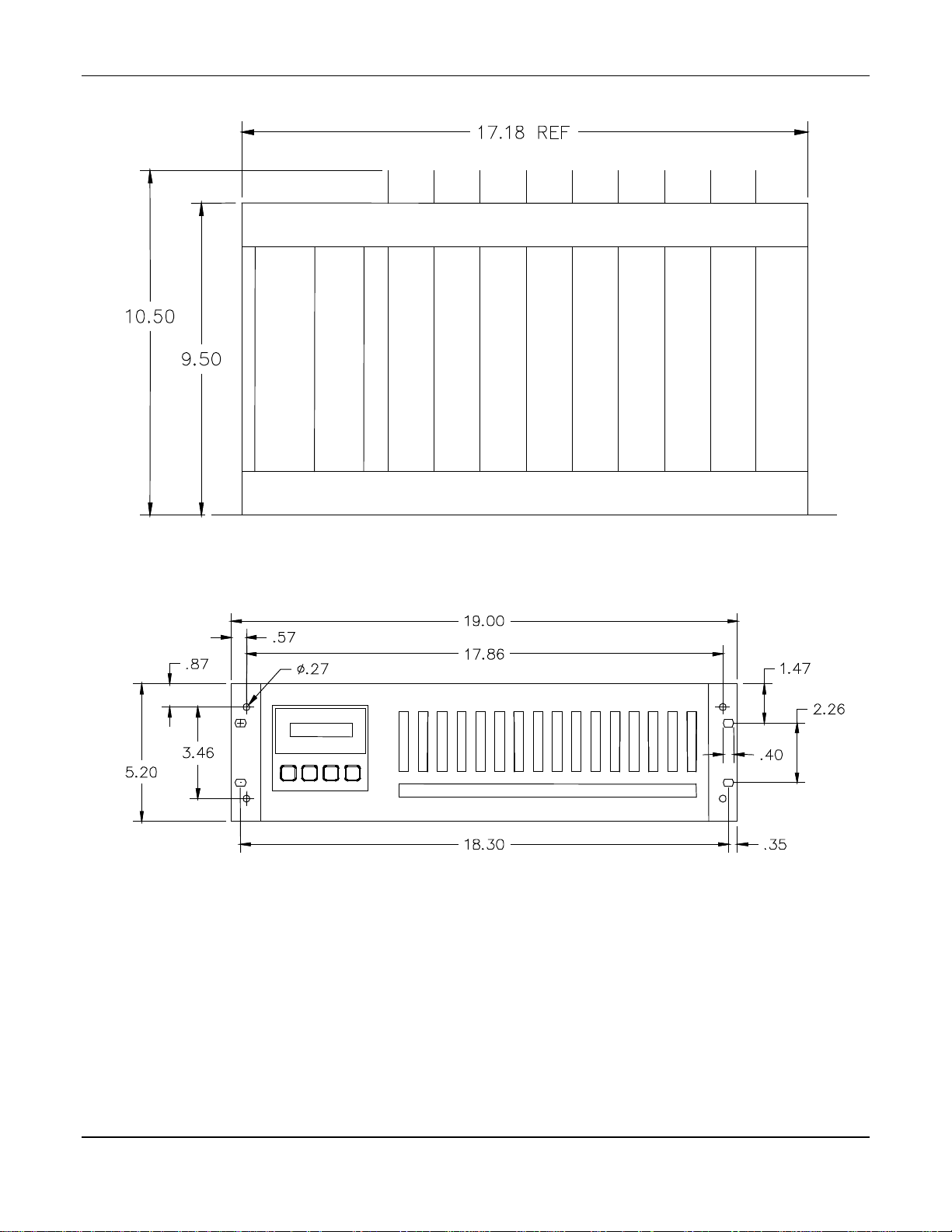
See Figure 1 for overall dimensions and Figures 2 and 3 for front and rear views.
Enclosure:
ONTROL
Overall dimensions
Function
Capacity
Measurement
Storage temperature
Operation temperature
Relative humidity
Visual
Display
Alarms
Audio Alarms Alarm remote acknowledgement
Inputs Active 2-wire or 3-wire shielded cables according to the type of
Signal Outputs
Rack 3U 19″
Control
16 measuring channels
Continuous
–20 C to +55 C
–10 C to +45 C
0 to 95% humidity, no condensation
Fluorescent display panel, 2 lines of 16 characters
80 LED (power on, gas alarms, faults)
sensor/transmitters
Resistance in loop mode 4-20mA, 2-wire or 3-wire 56Ω (2,000m with wire 1.5
mm2 at 20 C)
4-20mA analog per channel, maximum load resistance = 600Ω
Serial: RS 485 / J BUS, common
Relay Outputs 2 independent alarm relays per channel
1 common relay for alarm 3 or audio alarm transfer
1 common fault relay
Power Supply AC or DC power supply
103 to 122 V
207 to 244 VAC (Optional)
21 to 31 V
Power consumption: 300 Va or 240 W
N
OTE
: All specifications stated in this manual may change without notice.
AC
DC
2
Page 7
MX52 C
ONTROL
ENMET Corporation
Dimensions are in inches
Top View
Front View
Figure 1: MX52 Overall Dimensions
3
Page 8
ENMET Corporation MX52 C
ONTROL
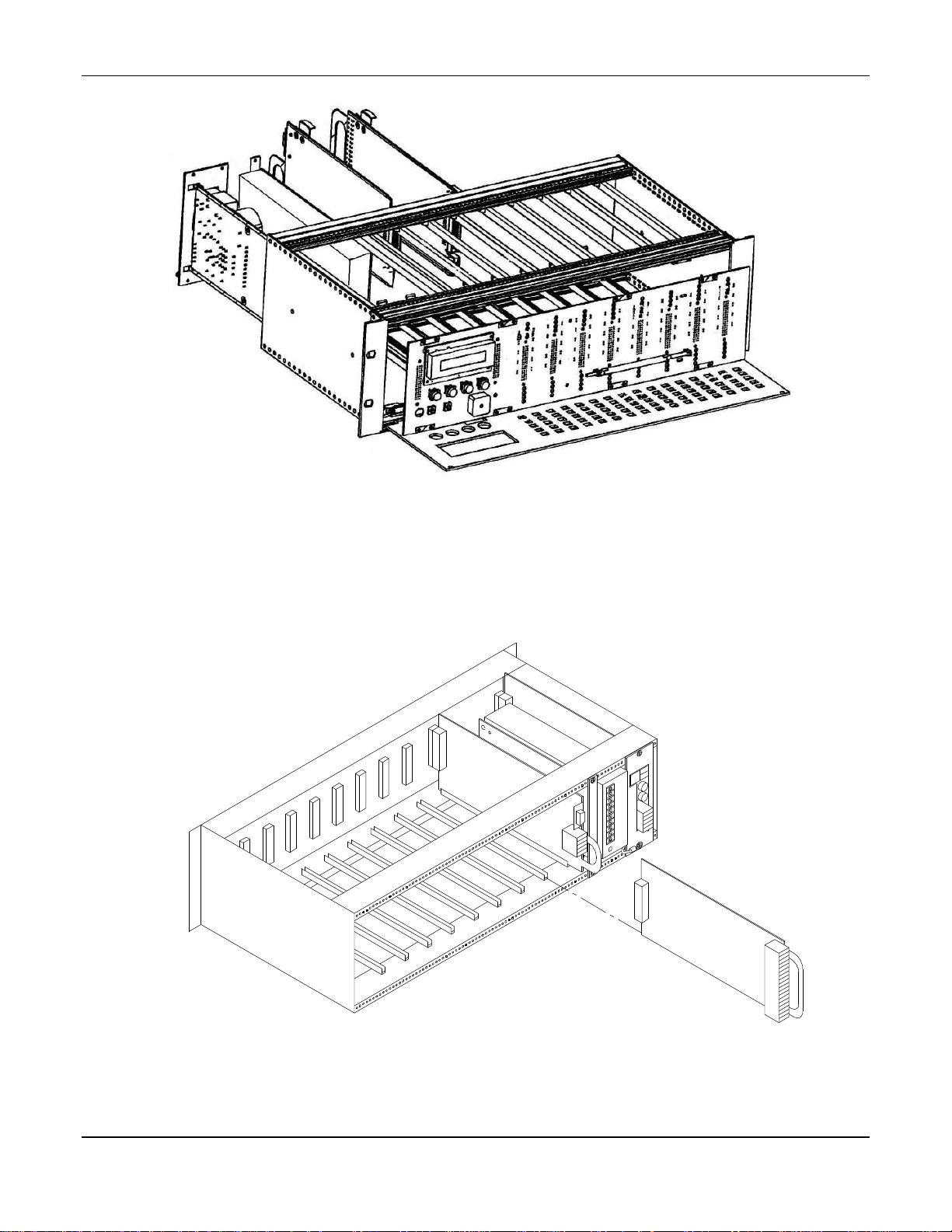
Figure 2: MX52 C
ONTROL
Front View, Internal
Figure 3: MX52 C
ONTROL
4
Rear View
Page 9
MX52 C
2 channels per board
Buzzer
3.0 Features
3.0 Features
3.0 Features3.0 Features
ONTROL
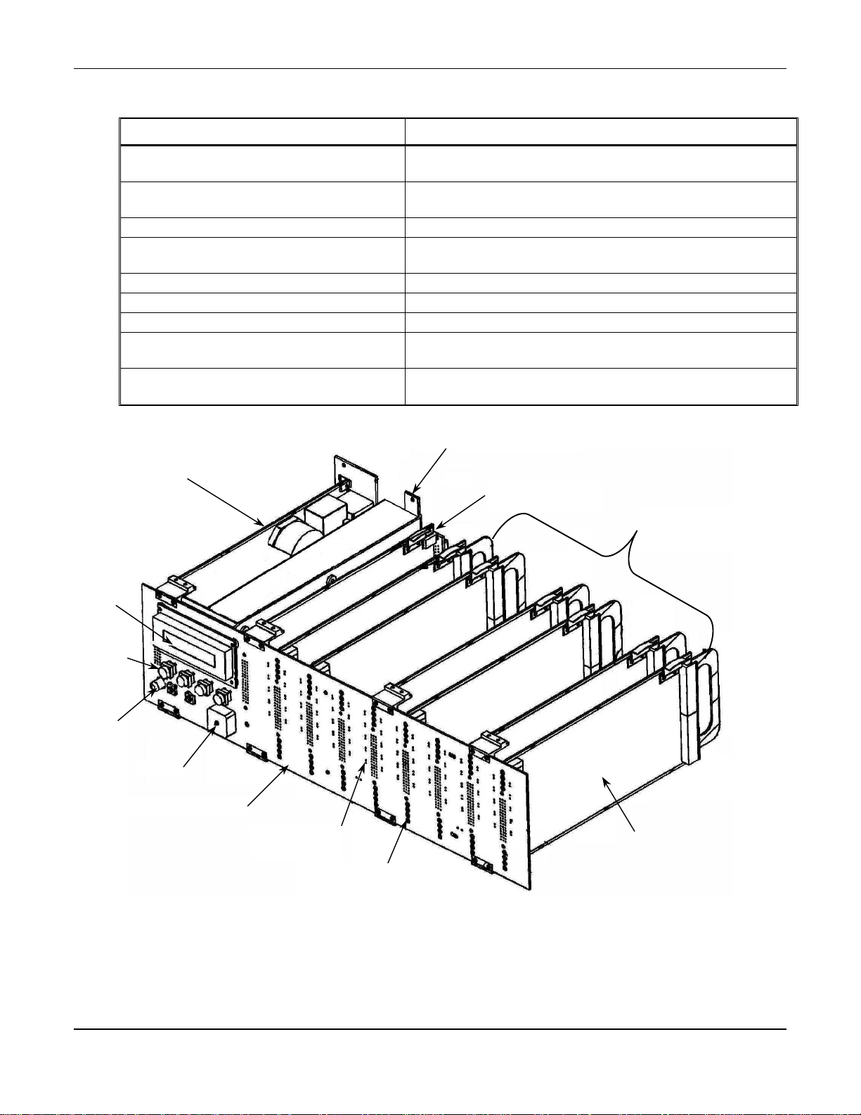
See Figure 4 for features.
Power Card
Display
On/Off Pushbutton Switch
Keypad
Buzzer
LEDs
Interconnect board
Channel Boards
Micro Board
Description Function
Internal power supply
See figures 5 for detail.
For visual display of:
Channel, Gas (type and reading), Data when programming etc…
To power up and remove power of the MX52 C
Pushbutton switches used in programming and calibration
See figure 10 for detail
For audio alarms
For visual alarms
Interface for: Channel boards, Display, Keypad, LED and Buzzer
Control for each channel: .2 channels per board
See figure 7 for detail.
Connection for remote access of MX52
See figure 9
Power Supply
Refer to Figure 5
ENMET Corporation
ONTROL
Power Supply Card
Refer to figure 5
Display
Keypad Area
Pushbutton switches
On/Off
Pushbutton
Switch
FRONT interconnect board
Rows of LEDs
for each channel
Rows of POTs
for each channel
Micro Board
See figure 9 for detail
8 Channel boards
• 2 channels per board
See figure 7 for detail
Channel board
Figure 4: MX52 C
ONTROL
5
Features
Page 10
ENMET Corporation MX52 C
Note:
4.0 Installation
4.0 Installation
4.0 Installation4.0 Installation
4.1 Installation recommendations
The MX52 C
ventilated and monitored location, such as guardhouse, control room, instrumentation room, etc.
The control can be mounted in any standard 19″ rack. See Figure 1 for dimensions. Optional enclosures and wall
shelves are available.
Before making any connections, switch off the power using the main On/Off switch below and to the left of the
FRONT circuit (see Figures 4 and 10).
ONTROL
can be installed in any area without a hazardous atmosphere. It should preferably be placed in a
ONTROL
Power Supply Terminal
Earth Ground
Terminal
Power connections are located on a terminal strip in this location.
Note the location of the relevant positions as labeled on the terminal
strip and wire accordingly. Positions of the AC & DC contacts may
vary depending on the required power supply
Figure 5: Power Board and Module
6
Page 11

MX52 C
ONTROL
ENMET Corporation
4.2 Electrical Connections of the MX52 C
ONTROL
4.2.1 Power Supply
Voltage: 115 VAC (103 to 122 V) 50/60 Hz
Maximum power: 300 VA
Maximum current in cable: 1.5 A
Power wire, 3 conductors, 16g
Location of connection terminal blocks, see Figure 5
Protection: Overvoltage Clamp, 130 – 150% & Current Limit 130% typ, Self-Reset Foldback
Voltage: 207 to 244 V
W
ARNING
C
AUTION
:
Continuous gas detection and alarm systems (110VAC/220VAC /24VDC/12VDC powered) become
inoperative upon loss of primary power. Contact factory for specifications and pricing of backup
battery systems.
:
It is mandatory that the instrument must be grounded to earth ground. This normally occurs through the ground
(green) wire of the AC power system. A terminal is also reserved for this purpose at the back of the power card,
see Figure 5. The ground connection is required in order to ensure correct operation of the following
• Power interference filter
• Protective devices against electromagnetic interference
AC
- 50/60 Hz on option
4.2.2 DC Power supply
Voltage: 21 to 30 V
Maximum power: 240 W
Maximum current in cable: 12.5 A
Cable: 2 x 14g
Location of terminal block, see Figure 5
Protection: Two fuses located at the back of the power card. See figure 5
DC
4.3 Channel Board Connections
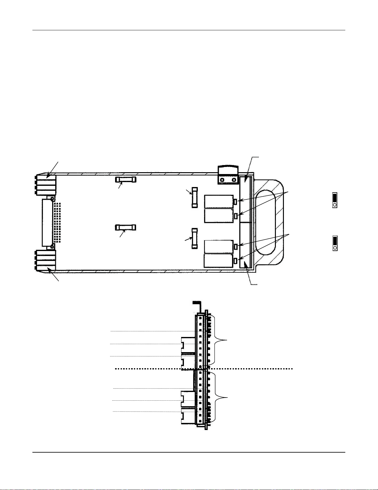
Each channel board includes terminal strips for each of two channels. The terminal strips for odd-numbered channels
are at the top, the terminal strips for even-numbered channels are at the bottom of each channel board. Figure 7 shows
these I/O terminal strips and identifies the positions on them.
4.3.1 Sensor/Transmitter
Sensor/Transmitters are connected to positions C1, C2 and C3 on each channel terminal strip. Connections are as follows:
Two Wire Sensor/Transmitter Three wire Sensor/Transmitter
C1 Signal, minus C1 Signal
C2 Not used C2 Ground
C3 Signal, plus and +24VDC power C3 +24VDC power
4.3.2 4-20mA Output Signal
The next two (+ 4-20mA –) positions in each terminal is the 4-20mA output from the C
sides of the loop are indicated on the terminal strip.
4.3.3 Relay Contacts
MX52 C
indicated in Figure 7. These relays have a maximum capacity of 2 Amp at 230 Volts, and are programmed as described
in Section 4.4.1. Open or closed contacts are selected with jumpers on the channel board as indicated in Figure7.
Figure 8 shows an example of external devices controlled by the MX52 C
The system alarm relay contacts AL3 are on the power supply board, as shown in Figure 5.
ONTROL
relay contacts for the first two alarm levels are on the next four positions on the terminal strips, as
ONTROL
4.3.4 Wiring Requirements
Sensor/Transmitters: Wiring to the sensor/transmitters should be by two or three wire shielded cable. The
recommended cable is 18 gauge three wire, ENMET part number 66017-006, Alpha-1747C or equivalent.
Output Loop: Wiring to output loop should be similar two wire shielded cable.
Relay: Relay wiring must be suitable insulated wire.
ONTROL
relay contacts.
. The plus and minus
7
Page 12
ENMET Corporation MX52 C
Output connector
Output connector
Signal Fuse
Signal Fuse
Line Fuse
Line Fuse
Odd-numbered channel
Potentiometers
Potentiometers
2
4-20mA
4-20mA
Relay Alarm 2
End View
End ViewEnd View
End View
Signal Fuse
Signal Fuse
Side View
4.4 Connecting the MX52 C
ONTROL
to External Devices
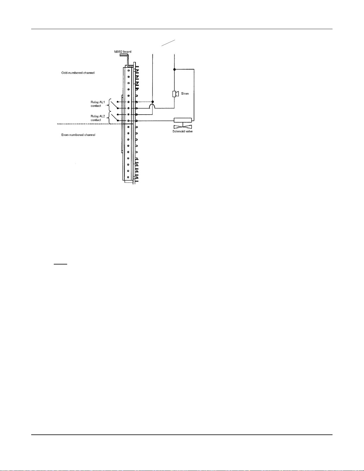
4.4.1 Alarm Relays
The 16 channels of the MX52 C
devices such as sirens, solenoid valves, extractors, telephone callers, etc… Auxiliary alarms should be powered from
an independent power source separate from instrument power to avoid alarm failure due to controller malfunction.
An example of connection is given in Figure 8
F
OR EACH CHANNEL
:
The following relays are available (see Figure 7 and 12):
A relay associated with the triggering of alarm 1.
A relay associated with the triggering of alarm 2.
Use of open or closed contacts selected with a jumper (see Figure 7).
Use of positive or negative safety selected by programming (see the CHANNEL programming menu).
Contact outputs on the back of the two channel PCB (see Figure 12).
F
OR SYSTEM RELAY
:
A relay associated with the triggering of alarm 3.
A relay associated with the triggering of a system fault.
Odd-numbered channel
ONTROL
unit are each equipped with two relays that can be used to control external
Odd-numbered channel
See End view, below
ONTROL
Even-numbered channel
Even-numbered channel
Odd-numbered channel
Even-numbered channel
Even-numbered channel
Even-numbered channel
C1
C2
C3
Relay Alarm 1
RL
RL
Odd-numbered channel
Relay Al1
odd channel
Relay Al2
odd channel
Relay Al1
even channel
Relay Al2
even channel
Even-numbered channel
See End View, below
+
–
1
Output connector
Odd-numbered Channels
Jumpers
Open/closed contacts
Factory set NC
Even-numbered channel
Jumpers
Open/closed contacts
Factory set NC
Relay Alarm 1
Relay Alarm 2
Figure 7: Channel Board
C1
C2
C3
RL
RL
+
–
1
2
Output connector
Even-numbered Channels
8
Page 13
MX52 C
ONTROL
N
OTE
: Auxiliary alarms should be powered from an independent
110V
AC
power source separate from instrument power to avoid
alarm failure due to controller malfunction.
Figure 8: Example of External Device Connection
ENMET Corporation
A siren connected to relay AL1 is actuated when alarm 1 is triggered,
A solenoid valve connected to relay AL2 is actuated when alarm 2 is triggered.
F
OR ALL CHANNELS
A common relay is associated with the triggering of alarm 3 for any and all of the 16 channels.
By programming, this common relay can also be used for the remote transmission of the audio warning signal. This
relay is then associated with all the control alarms. (See Figure 5)
A Fault relay associated with the triggering of channel faults (detector failures, electrical connections, excessively
negative zero, etc.). The Fault Relay is normally closed, it opens when in fault condition.
Common relay contact outputs are on the back of the power card: Figure 5.
N
OTE
: The breaking capacity of the MX52 C
ONTROL
relay contacts is 2 A / 250 V
AC
or 30 VDC, so external
intermediate relays must be used if the devices to be controlled require high current levels.
4.4.2 The 4-20mA Current Outputs
For each channel, the MX52 C
sensor/transmitter outputs to a recorder, an external PLC or a computer. The maximum resistance in loop mode is 600
ohms. The ground connections for the 4-20 mA outputs are common. The 4-20 mA lines are not galvanically
insulated one from the other. The current output varies according to the situation and has several conditions other than
normal, as follows:
On starting up the unit: I < 1 mA
With FAULT: I < 1 mA
In MAINTENANCE mode: I = 2 mA
ZERO MEASUREMENT: I = 4 mA
Full scale: I = 20 mA
Out of range or “in doubt”: I > 23.2 mA
ONTROL
is equipped with a 4-20 mA output that can be used to retransmit
9
Page 14
ENMET Corporation MX52 C
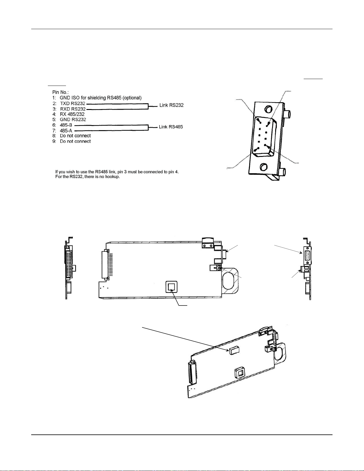
4.4.3 Series Output
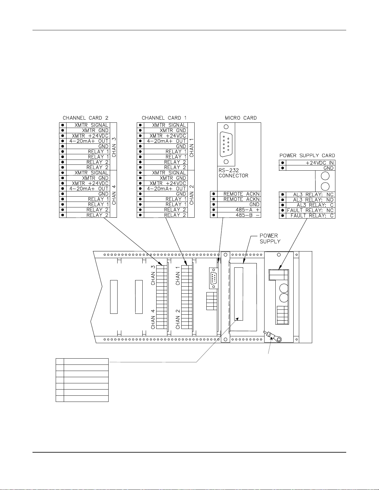
A single “sub. D” connector located on the back of the micro board is equipped with both an RS485 output in J-BUS
format for the uploading of data from the MX52 unit to a computer and an RS 232 output for programming of the
MX52 C
C
AUTION
Several MX52 C
number is assigned to each MX52 C
ONTROL
:
A computer must be used in order to printout the data stored by the MX52 C
external environment. See Figure 9A for details of the pinout of this connector.
ONTROLS
can be connected to a single computer which is the “MASTER”. In this case, a SLAVE
ONTROL
.
Pin 1
ONTROL
.
Pin 6
ONTROL
Pin 5
Figure 9A: Pinout of the MX52 Serial Link Connector Sub D
4.4.4 Remote Acknowledgement
It is possible to allow remote acknowledgement by connecting a momentary push-button, to the terminals provided for
that purpose on the back of the micro board: see Figure 9.
M
ICRO BOARD
part number 02625-002
M
ICRO BOARD
part number 02625-003
Used to isolate Signal Ground from Chassis Ground.
Desirable when connecting several MX52 control units
together as in a “Master”, “Slave” situation, or when
using a computer/PLC setup.
: Standard
Connector Sub D
Output RS485
See Figure 9A
Connector for Remote
Acknowledgement of
Alarm
Micro Processor
: with Galvanic Isolation
Pin 9
Figure 9: Micro Board
10
Page 15

MX52 C
See detail 10a below
5.0 Operation
5.0 Operation
5.0 Operation5.0 Operation
ONTROL
ENMET Corporation
5.1 Starting Up
5.1.1 Checking the Installation
Ascertain that all connections have been made and that the complete installation complies with current standards in
force.
W
ARNING
:
ENMET Corporation is not responsible for the compliance of the complete electrical safety system.
The MX52 C
ONTROL
power input should be protected with circuit breakers provided for that purpose, and that assure
protection of the power unit. The circuit breakers are to be selected according to the power consumption levels
specified by the manufacturer and the length of the electric cables. The circuit breakers can also be used to interrupt
power to the control
Display
Keypad area
Item D
On/Off switch
Item A
Programming switch
Item B
Calibration switch
Optional
Buzzer switch
Item C
Detail 10a: Optional Buzzer switch
Figure 10: Operation Components
11
Page 16

ENMET Corporation MX52 C
Line corresponding to
ONTROL
5.1.2 Switching the MX52 C
To start up the MX52 C
Swivel the front panel.
Press the ON/OFF button located to the bottom left-hand side of the FRONT circuit: see Figures 4 and 10 (item A).
The display panel then shows, for example:
ONTROL
ONTROL
:
On
ENMET
MX48/52 V2.0r12
The unit then goes into INITIALIZATION mode for one minute. Consequently, all the alarms are inhibited and the
current outputs are 1 mA for the channels in service. The unit then performs a self-test on its buzzer and all its lightemitting diodes. At the end of this one-minute period, the channels in service return to normal operation and the
corresponding alarms and relays are enabled.
The user can carry out a “manual-self test” by pressing the test key at any time (see Figure 10).
This self-test lasts 20 seconds and the display panel may show the following displays one after the other, for example:
Channel 1
XX ppm Cl2
Then
the channel displayed
when the ENTER switch
was pressed
******* SELF-TEST ******
XX ppm Cl2
The user can interrupt the self-test cycle before it is completed by pressing the ACKNOWLEDGEMENT switch.
N
OTE
: In some applications, slight electronic noise between the Sensor/Transmitter and the Control can cause
fluctuations in the display reading. These minor fluctuations are considered to be insignificant in terms of the
range, detection limit and alarm values of the gas being monitored.
5.2 Operating Modes
5.2.1 Audio Alarm (Buzzer)
In normal operation, the audio alarm is triggered whenever a fault or an alarm threshold is exceeded. The audio alarm
can be stopped by pressing the ACKNOWLEDGEMENT switch or by remote acknowledgement. The buzzer makes a
continuous or pulsed sound, according to the programming of the control, when an alarm threshold is exceeded.
12
Page 17

MX52 C
Illumination of
ONTROL
ENMET Corporation
5.2.2 Light-emitting diodes (LED) (Figure 10)
Each channel is equipped with five LEDs, when are visible and identified on the FRONT panel.
LED Extinguished Illuminated steady mode Flashing
GREEN Channel not in service Channel in service Channel in service
1st red AL1 not triggered Threshold AL1 exceeded
(automatic clearing)
2nd red AL2 not triggered Threshold AL2 exceeded
(automatic clearing)
3rd red AL3 not triggered Threshold AL3 exceeded by
mean or time
(automatic clearing)
Threshold AL1 exceeded
(manual clearing)
Threshold AL2 exceeded
(manual clearing)
Threshold AL3 exceeded by
mean or time
(automatic clearing)
Yellow No fault Fault on channel - Channel being calibrated or
programmed
- Detector being calibrated
5.2.3 Alarm Thresholds
Each of the three alarm thresholds can be programmed independently for each channel. (See the “Channel
programming” menu).
In normal operation, a gas alarm is only triggered after a preprogrammed time delay in order to avoid spurious alarms.
Alarm thresholds can be processed in the following manners:
In normal cycle with manual clearing: block diagram 1.
In normal cycle with automatic clearing: block diagram 2.
In parking cycle: block diagram 3.
The alarm thresholds are to be selected according to the gases detected and the corresponding standards in force.
T = Time of 5 seconds or alarm 3 time delay
START
Alarm acknowledged
Yes
LED extinguished
Relay disengaged
Buzzer stopped
No Yes
Threshold exceeded
flashing alarm LED
After T2 time
Relay engaged
Buzzer engaged
No
Alarm acknowledged
LED steady mode
Buzzer stopped
END
Illumination of
flashing alarm LED
Yes Yes
Time T exceeded
Alarm LED
extinguished
No
Yes
No
Block Diagram 1: Normal Cycle with Manual Clearing
13
Page 18

ENMET Corporation MX52 C
Starting of
Illumination of
T = Time of 5 seconds or alarm 3 time delay
START
ONTROL
No Yes
LED extinguished
Relay disengaged
Threshold exceeded
flashing alarm LED
After T2 time
Relay engaged
Buzzer engaged
Alarm LED illumi-
nated in steady mode
Yes No
Time T exceeded
END
Alarm LED
extinguished
Block Diagram 2: Normal Cycle with Automatic Clearing
Alarm 3 operates in the same way as the normal cycle.
The times defined for alarms 1 and 2 (time delays) are, in this case, used to define the minimum operating time for
each relay.
t AL1 tR1 R2 t AL2
Threshold AL2
Threshold AL1
t
AL1
t
AL2
t
R1 R2
Min. operating time for alarm 1
(defined for each channel)
Min. operating time for alarm 2
(defined for each channel)
Switching time from relay 1 to relay 2
(defined for the whole unit)
Starting of
relay R1
Stopping of
relay R1
relay R2
Block Diagram 3: Parking Cycle
14
Stopping of
relay R2
min.
t
1
t
2
t
R1 & R2
Page 19

MX52 C
ONTROL
ENMET Corporation
5.2.4 Fault Thresholds
Processing of detector faults, Each channel detects the following faults.
For toxic and explosive gas detectors:
line interrupted (0 mA),
line short-circuited or excessive consumption,
negative offset (more than 20% of measuring scale),
line in calibration mode (2 mA) (if confirmed by programming).
For sensor/transmitter for combustible gas type (4-20 mA and 340 mA) in normal mode, if the measurement is greater
than 100% of the measuring scale, the following occur immediately:
Display: SUP
The relays are actuated if the thresholds are exceeded.
The general fault relay is actuated.
The 4-20 mA output of the channel is greater than 20 mA.
All these states are memorized and the only way of acknowledging them is to switch off the channel and then
restart it.
Faults are valid after a preprogrammed time (in the same way as alarms).
* The LED is extinguished as soon as the fault disappears.
START
Wait until the fault has been present
for at least 5 seconds.
The relays are locked in their current state.
The common fault relay is engaged.
The buzzer is engaged.
The channel fault LED is illuminated. *
1 mA is sent on the 4-20 mA output.
END
Block Diagram 4: Fault
5.2.5 Standard Display
One minute after starting up, and if no test action is performed on the keypad, the unit successively scans all the
channels in service and displays the values.
Channel 1
XXX LEL CH4
Each channel is interrogated for 10 seconds.
The user can interrogate a channel manually by selecting that channel with the + and – switches to obtain a
manual display for one minute.
The user can return to normal cyclic scanning during that one-minute period by simultaneously pressing the + and
– switches. The display panel then shows alternating displays, three times in succession:
Examples of display:
normal scan
OR
For example:
THEN
XXX ppm CO
15
Channel 2
XXX ppm Cl2
Channel 5
XXX ppm CO
Page 20

ENMET Corporation MX52 C
5.3 Functions of Switches and Menus for Programming and Calibration of MX52 C
5.3.1 Keypad (see Figures 10 and 4)
The keypad is equipped with four touch switches accessible without opening and swiveling the MX52 C
FRONT panel. See Item D, Figure 10
ONTROL
ONTROL
ONTROL
––––
––––
++++
++++
AACCQQUUIIT
TTEESSTT /
EENNTTEER
––––
––––
- Manual display of previous channel
- Manual display of previous menu
- Decrease value, threshold, etc.
- Display of previous choice (on ← off, etc.)
- NO
- Combined with the “PLUS” switch to restart the channel’s automatic display cycle.
- Manual display of next channel
- Manual display of next menu
- Increase value, threshold, etc.
- Display of next choice (on ← off, etc.)
- YES
- Combined with the “MINUS” switch to restart the channel’s automatic display cycle.
- “Audio and visual” or “audio” clearing of an alarm
T
/
R
- Exit from a current menu
- Start a self-test manually
- VALIDATE
++++
++++
T
AACCQQUUIIT
TTEESSTT /
EENNTTEER
/
R
5.3.2 Maintenance Switches
PROGRAMMING key (Item B, Figure 10): accessible after opening and swiveling the front panel.
Combined with the “–” key to go back in a menu.
To quit normal display mode and access the various menus (see block diagram of the various menus).
To scroll through a menu.
CALIBRATION key (Item C, Figure 10): accessible after opening and swiveling the front panel.
To set a channel to CALIBRATION mode.
To quit that mode.
5.3.3 Potentiometers
On the FRONT circuit, each channel has four potentiometers (Item E in Figures 10 and 11). These are accessible by
opening and swiveling the FRONT panel of the MX52 C
TOP (item A) 1 sensor/transmitter ZERO potentiometer
1 sensor/transmitter sensitivity potentiometer
BOTTOM (item B) 1 potentiometer 4 mA / current output
1 potentiometer 20 mA / current output (for full scale)
ONTROL
16
and are laid out as follows (see Figure 11):
Page 21

MX52 C
-
EN TE R
-
-
ONTROL
ENMET Corporation
5.4 Menus
5.4.1 Menus and their Functions
The MX52 C
These five menus are as follows:
DESIGNATION FUNCTION
“CHANNEL” programming - To program the whole configuration of a channel (ON/OFF, range, alarm thresholds, etc...)
“SIMULATION” programming - To artificially vary a channel measurement on:
“CHANNEL COPY” programming - To copy the complete programming from one channel to another (time saving)
“UNIT” programming
“UPLOADING” programming - To transfer data, measurements and events, etc., from the unit to a computer via the MX52
The bock diagrams for these menus are in sections 5.4.4 through 5.4.8.
5.4.2 Legend for Block Diagrams of Programming Menus
It is easy to use these various menus by means of the switches on the keypad and the “Programming” switch (Items B
and D, Figure 10).
Detailed flow diagrams of the menu scrolling function and of each menu are given on the following sections.
ONTROL
has five menus that are accessed by pressing the “Programming” switch (Item B, Figure 10).
- the display panel,
- the 4-20 mA current output.
- To trigger the alarms (LED and relays) at the same time.
- To program the whole configuration of the MX52 C
C
ONTROL
RS 485 / J BUS output.
Programming switch
ONTROL
(language, slave number, etc.).
P
+
T
AACCQQUUIIT
P
[ ]
(1) Free
Set to
Set to 1
++++
++++
––––
––––
/
TTEESSTT /
R
EENNTTEER
This switch can also be used to exit from the current menu.
When in a menu, you can go back (to make checks or modifications, etc...) by
pressing and holding down switch
Programming switch.
Parameters specified in square brackets [ ] are the VALID parameters (in memory).
This means that the relay can be controlled freely in positive or normal safety mode
(programming by MX52).
This means that the relay will be controlled, set to 0 or 1, and programmed directly via
the J.BUS input and the “
Switch used to move forward
Switch used to move in reverse
Switch used to enter data
and by successively pressing and releasing the
COM
52” software.
17
Page 22

ENMET Corporation MX52 C
–
+
–
+
–
–
To program the whole configuration of a channel
To artificially vary a channel measurement on:
To copy the complete programming from one channel to another
To transfer data, measurements and events, etc., from the unit to a
5.4.3 Bock Diagram of Scrolling Programming Menus
NORMAL
DISPLAY
P
ONTROL
Programming
[Channel xx]
Programming
Simulation [Channel xx]
Programming
Copy [Channel xx]
+
Programming
Control Unit
+
(ON/OFF, range, alarm thresholds, etc...)
- the display panel,
- the 4-20 mA current output.
To trigger the alarms (LED and relays) at the same time.
(time saving)
To program the whole configuration of the MX52 C
(language, slave number, etc.).
ONTROL
Programming
Reprogramming
computer via the MX52 C
18
ONTROL
RS 485 / J BUS output.
Page 23

MX52 C
-
←
+
ENTER
+→+→+→+→+→+
ENTER
+
+
ENTER
+
→
-
ENTER
+
→
-
ENTER
Seuil
Alarme 1
Channel
xx
Measuring range
Decimal point
Alarm 1 threshold
Alarm 2 threshold
ONTROL
5.4.4 Block Diagram of Channel Programming Menu
NORMAL
[25]
DISPLAY
ENMET Corporation
P
Programming
[Channel xx]
P
[Off]
P
[1
]
P
[1.]
: Last channel displayed
: Off On
→
: CHOICE OF RANGES
1 31 3 1 2
xxxx U
: SELECTION OF POINT POSITIONING
1 1. 1. .1 .1
.1
→+→+→+→
then
then
then
P
[25]
P
[5]
Continued On Next Page
: to 2
←
: to 2
←
19
then
then
Page 24

ENMET Corporation MX52 C
+
←
-
ENTER
-
←
+
ENTER
-
←
+
ENTER
-
←
+
ENTER
-
←
+
ENTER
Alarm 2
Alarm 3 threshold
Alarm 3
Cycle
Continued From Previous Page
P
: to 2
[75]
P
→
then
ONTROL
Alarm 1
[Increasing]
P
[Increasing]
P
[Increasing]
P
: Increasing Decreasing
→
: Increasing Decreasing
→
: Increasing Decreasing
→
: Normal Parking
→
then
then
then
then
[Normal]
P
Continued On Next Page
20
Page 25

MX52 C
-
←
+
ENTER
-
←
+
ENTER
-
←
+
ENTER
-
←
+
ENTER
-
←
+
ENTER
-
←
+
←
+
ENTER
Ack alarm 1
Ack alarm 2
Alarm 3
Relay 1 safety
Relay 2 safety
Relay 1
ONTROL
Continued From Previous Page
[Manual]
P
[Manual]
P
[Time Lag]
Manual Automatic
→
Manual Automatic
→
Time delay Mean
→
ENMET Corporation
then
then
then
P
[Positive]
P
[Positive]
P
[Free]
P
Negative Positive
→
Negative Positive
→
Free Set to Set to 1
→
then
then
→
then
Continued On Next Page
21
Page 26

ENMET Corporation MX52 C
-
←
+
←
+
ENTER
-
←
+
←
+
ENTER
-
←
+
←
+
ENTER
-
←
+
ENTER
+
←
-
ENTER
-
←
+
←
+
ENTER
Relay 2
Relay 3
Fault relay
Auto Calibration
Gas
Channel
xx
Continued From Previous Page
Free Set to Set to 1
[Free]
P
[Free]
P
[Free]
→
Free Set to Set to 1
→
Free Set to Set to 1
→
→
→
→
then
then
then
ONTROL
P
[No]
P
[Premises 1 channel] U
P
[CH4]
P
Flashing
The MX52 unit can detect and indicate (with a flashing
yellow LED) that a line has-been placed in CALIBRATION
mode on the detector.
No Yes
→
Free display: A channel heading can be programmed
(in 13 characters maximum). By default, the channel
number is displayed in this area.
→
CH4 CO 2S etc.
→
then
then
→
then
Continued On Next Page
22
Page 27

MX52 C
-
←
+
←
+
ENTER
-
←
+
ENTER
-
←
+
ENTER
-
←
+
ENTER
-
←
+
←
+
ENTER
Units
Alarm 2 time
Alarm 3 time
Alarm 1 time
Detector type
ONTROL
Continued From Previous Page
[LEL]
P
[00:00:05]
HH : mn : sec
P
[00:00:05]
ENMET Corporation
LEL % ppm etc.
→
Time: Time interval between the triggering of the AL LED and
of the corresponding relay, or the minimum operating time of
the relay in parking mode.
→
N
OTE
: Factory default setting is 5 seconds.
Display of time by using switches
→
N
OTE
: Factory default setting is 5 seconds.
→
then
then
then
HH : mn : sec
P
[00:00:05]
HH : mn : sec
P
[Explosive]
P
E
ND OF MENU
Text
→
N
OTE
: Factory default setting is 5 seconds.
: Explosive Toxic Spec. tox.
→
then
→
then
23
Page 28

ENMET Corporation MX52 C
-
←
+
5.4.5 Block Diagram of Simulation Programming Menu
NORMAL
DISPLAY
ONTROL
P
Programming
[Simulation xx]
Programming
[Simulation xx]
Channel xx
+
ENTER
P
→
Simulation on previously displayed and [validated] channel
Free labeled area
S = flashing to indicate that this channel is in
simulation mode.
LEL CH4 S
To artificially vary measurement on the display panel, on
the 4-20 mA output, and trigger alarms (LED and relays)
ACK
E
ND OF MENU
= ESCAPE
To exit from this menu and return to normal operation
24
Page 29

MX52 C
-
←
+
ONTROL
5.4.6 Block Diagram of Programming Copy Channel
NORMAL
DISPLAY
ENMET Corporation
P
+ +
Programming
Copy channel xx
ENTER
Programming
[Copy channel xx]
P
Copy channel
[Channel xx => xx]
ENTER
Last channel displayed
Validation of menu
Validation of channel to be copied
: Copy the channel’s configuration to another
channel
xx = indication of “Other channel
number” using keys
: Validation of copy
→
Copy channel
[Channel xx => xx]
E
ND OF MENU
25
Page 30

ENMET Corporation MX52 C
+
+
ENTER
+→+→+→+
ENTER
+
ENTER
5.4.7 Block Diagram of Programming Control Unit
NORMAL
DISPLAY
ONTROL
P
++ +
Programming
Unit
ENTER
Programming
[Unit]
Language
[English]
Validation of menu
P
Choice of languages:
: French, English, German, Spanish
→+→
P
then
Speed
[96
]
P
Slave address
[1]
P
Continued On Next Page
26
Choice of transmission speed with computer:
12 24 48 96 192 Bauds
then
Choice of slave address (this unit)
to 25
→
then
Page 31

MX52 C
-
←
+
ENTER
-
←
+
ENTER
-
←
+
ENTER
-
←
+
ENTER
-
←
+
ENTER
-
←
+
ENTER
ONTROL
ENMET Corporation
Continued From Previous Page
Response time
[00:00:05]
HH: mn : sec
P
Relay 1&2 stop T
[00:00:05]
HH: mn : sec
P
Relay safety
[Negative]
P
Buzzer transferred
[NO]
P
This is the time interval between exceeding of
the AL threshold and triggering of the
corresponding visual alarm (LED).
Display the time using keys:touches
→
→
→ then
→ then
→ then
→ then
→
In “Parking” mode: this is the time interval
between stopping of relay 1 and starting up of
relay 2.
Display the time using keys:
→
Negative Positive
Control of relay 3 (common) by any triggering
of buzzer
NO YES
Buzzer connected
[Yes]
P
Continuous buzzer
[Yes]
E
ND OF MENU
27
Utilization of common audio alarm (buzzer)?
(Function in series with buzzer jumper)
NO YES
→ then
→ then
→
YES = Continuous sound
NO = Discontinuous sound
NO YES
→
Page 32

ENMET Corporation MX52 C
5.4.8 Block Diagram of Reprogramming Programming
NORMAL
DISPLAY
ONTROL
P
++ + +
Programming
Display of menu
Uploading
ENTER
Validation of utilization
of menu
Programming
[Uploading]
P
Uploading
Confirm
Display of menu
confirmation
Data transfer request
Validation of data
transfers
ENTER
28
Uploading
[Confirm]
E
ND OF MENU
Confirmation of
uploading
Page 33

MX52 C
ONTROL
ENMET Corporation
5.5 Startup of the MX52 C
W
ARNING
:
The handling operations and adjustments described in this section must be performed by authorized
ONTROL
personnel only, as they are liable to affect detection safety.
Once the control has been switched on, it can be programmed, the channels can be programmed according to the
sensor/transmitter used, and the control and sensor/transmitter can be calibrated. The programming operations can be
carried out directly on the MX52 C
with the “
COM
52” software.
ONTROL
according to the following procedures, or by using a computer equipped
5.5.1 Programming the Control
To program the MX52 C
conjunction with the keypad and the “Programming” switch. Then, the instructions in the menu should be followed
carefully.
N
OTE
: If the control is left in the programming mode for more than 30 minutes, it automatically switches to fault mode.
ONTROL
the “Unit programming” menu must be used (see Section 5.4 on Menus) in
5.5.2 Programming the Channels
•
• Programming
••
To program each channel according to the type of sensor/transmitter used, the “Channel programming” menu must be
used (see Section 5.4 on Menus) in conjunction with the keypad and the “Programming” switch. Then, the menu
instructions should be followed carefully.
When a channel is switched on, all its relays are in “off” mode and its current output is 1 mA. One minute later, the
channel comes into effective operation, with relays ready and output of 4-20 mA.
N
OTE
: If the control is left in the programming mode for more than 30 minutes, it automatically switches to fault mode.
•
• Copy
••
In order to make the programming of ALL CHANNELS less TIME-CONSUMING when the same programming is
required for a number of channels, it is recommended that the “COPY” menu be used (see Section 5.4 on Menus) in
conjunction with the keypad and the “Programming” switch. Then, the instructions in this menu should be followed
carefully.
5.5.3 Calibrations
When it is first switched on, with the C
carried out on both the C
ONTROL
Channel connected to a sensor/transmitter supplying a standard 4-20mA current.
Prepare the sensor/transmitter for calibration:
Set the zero and gain of the sensor/transmitter according to the instructions furnished with that device.
N
OTE
: When the sensor/transmitter and C
should be in normal operating mode, but the MX52 C
inhibit the relays.
Note that with ENMET sensor/transmitters there are two ways of checking the signal supplied to the control:
By direct reading on the sensor/transmitter display.
By using a milliammeter to measure the current on the terminals provided for that purpose (see the manual for
the sensor/transmitter concerned).
Adjust the sensor/transmitter zero: If the ambient air is not pure, use air from a cylinder. When the signal is stable,
adjust the sensor/transmitter zero current output to 4 mA.
Prepare the MX52 C
Adjustment of the MX52 C
1. First adjust MX52 C
ONTROL
ONTROL
ONTROL
for calibration:
for the channel (Item A, Figure 11) read ZERO on the MX52 display.
2. Second adjust the MX52 C
ONTROL
corresponding 4 mA potentiometer: (Item B, Figure 11).
This current is read by connecting a digital miltimeter directly to the corresponding current output (see Figure 12).
ONTROL
and channels programmed, CALIBRATING operations must be
and the Sensor/Transmitters.
ONTROL
channel are calibrated at the same time. The sensor/transmitter
ONTROL
should be set to calibration mode in order to
potentiometers affect the other settings, so adjust them in the order listed.
display to zero, adjust the Control channel zero by using on the ZERO potentiometer
zero current output, adjust the 4-20mA current output to 4 mA by using the
29
Page 34

ENMET Corporation MX52 C
Calibrate the sensor/transmitter:
Adjust the sensor/transmitter gain.
Apply appropriate calibration gas to the sensor.
When signal has stabilized, set the sensor/transmitter gain according to the instructions furnished with that device
Calibrate the MX52 C
3. Third match the MX52 C
ONTROL
ONTROL
:
display to the S/T display, set the value of the calibration gas on the MX52
display panel by using the channel sensitivity potentiometer (Item A, Figure 11).
4. Finally set the MX52 C
ONTROL
current to the calibration output, adjust the current output by using the 20 mA
potentiometer to the appropriate output for the calibration gas being used (Item B, Figure 11).
Example of calibration current output: For a channel with a scale of 0 – 100 ppm:
If 100ppm gas is used to calibrate the S/T, the calibration current output should be set to 20mA
If 50ppm gas is used to calibrate the S/T, the calibration current output should be set to 12mA
ONTROL
Conclude Calibration of the MX52 C
ONTROL
:
Stop the injection of calibration gas, wait for the measurement to return to zero (on the MX52 display panel).
Then, press the “CALIBRATION” key (Item C, Figure 10). The flashing yellow LED goes out and the “C” on
the display panel disappears. The channel now operates normally and calibration has been completed.
Figure 11: Potentiometer Layout on Front of Channel Board
30
Page 35

MX52 C
+
+ +
+
–
– –
–
+
+ +
+
–
– –
–
6.0 Maintenance
6.0 Maintenance
6.0 Maintenance6.0 Maintenance
W
ONTROL
ARNING
:
The handling operations and adjustments described in this section must be performed by authorized
personnel, as they affect detection safety.
6.1 Periodic / Preventive Maintenance
ENMET Corporation
6.1.1 On the MX52 C
The MX52 C
available on the MX52 C
Check the functions of the control as follows:
Use the TEST switch to check the correct operation of all the LEDs and the buzzer.
Use the “SIMULATION” menu to check the correct operation of the display panel, the triggering of alarms
Cause a fault to occur (such as a line fault by disconnecting a detector wire) to check the correct operation of
ONTROL
(LED and relays), the auxiliary devices and the 4-20 mA current output.
the fault indications.
ONTROL
requires a small amount of maintenance. However, it is recommended that the test functions
ONTROL
unit be used to regularly test the essential functions of the control.
6.1.2 On the Sensor/Transmitters
Sensor/transmitters must be calibrated periodically according to instructions furnished with those units.
Figure 12: Channel Board, Outputs on Rear Connector
31
Page 36

ENMET Corporation MX52 C
6.2 Troubleshooting: Symptoms and Remedies
N
OTE
: ENMET and our representatives and distributors are available to supply you with calibration gas or a
maintenance contract.
S
YMPTOMS
C
AUSES
R
EMEDIES
ONTROL
Display channel not lighted and no
indicator lights on.
Fault indicator light on (in steady
mode).
Fault indicator light on (in steady
mode) and SUP displayed.
Continued on next page
On/Off switch in the Off position. Set the switch to the On position
(item A, Fig. 10).
Problem with AC supply or DC
power supply (24 V DC).
Check the supply voltages and, if
necessary, check the electric power
supply circuit breakers.
Mains fuses blown. Replace the mains fuses (see item
A, Fig. 5).
DC power (24 V DC) input fuses
blown.
Replace the 24 V DC fuses located
at the back of the MX52 unit (item
B, Fig. 5).
+24 V DC internal protection fuse
blown.
C
AUTION
:
Replace the +24 V DC fuse located
on the power board (item C, Fig. 5).
When replacing a fuse, use the required type and rating.
Faulty electrical connections on the
4-20mA sensor/transmitter wiring
Check the connections on the MX52
terminal block and the S/T terminal
block. Check that there is no short
circuit or break in the 4-20mA.
Faulty sensor/transmitter. Repair or replace the S/T.
The type of S/T does not match the
channel configuration.
Connect the correct type of S/T with
the corresponding channel.
CAUTION
The channel or wiring may be
damaged.
Negative offset too great (more than
20% of measuring scale).
Perform calibration on the S/T and,
then, on the control, if necessary. If
the problem persists, the sensor
must be replaced.
Channel in maintenance mode for
more than 30 minutes.
Return the channel to normal
operation by pressing the
Calibration key (Item C, Fig. 10).
The measurement is higher than
100% of the measuring scale.
To acknowledge the alarm, the
channel must be switched off and
then switched on again (by
programming).
If the problem persists and the
measurement is not consistent with
reality, the S/T must be calibrated.
32
Page 37

MX52 C
ONTROL
Continued from previous page
ENMET Corporation
An LED does not light up even
though the corresponding threshold
is exceeded and the buzzer and relay
are actuated.
An alarm is triggered, the LED lights
up and the relay is actuated but there
is no audio alarm.
The audio alarm stops after 30 s
although alarms are still actuated.
An alarm is triggered but the
auxiliary devices are not actuated.
Faulty LED. Perform a general test on the LEDs
by pressing the TEST switch on
the keypad (Figure 10) and, if the
LED still does not light up, the
programming must be modified by
using the “Unit programming”
menu (buzzer connected).
The buzzer switch is not correctly
positioned.
The buzzer is not programmed as “in
service”.
Position the buzzer switch correctly
(item F, Figure 10).
If the audio alarm is wanted, the
programming must be modified by
using the “unit programming” menu
(buzzer connected?).
The buzzer is programmed to operate
for 30 seconds only.
If the buzzer is to be sounded as
long as the alarms are actuated, the
programming must be modified by
using the “Unit programming
menu” (continuous buzzer?).
The relays are faulty. Short-circuit or open the relay
contact (as applicable) on the MX52
terminal block (Figure 12) and, if
the auxiliary devices operate
normally, the corresponding
channel board must be repaired by
an approved technician.
Remote acknowledgement is
impossible.
Faulty electrical connections. Short-circuit or open the relay
contact (as applicable) on the MX52
terminal block (Figure 12) and, if
the auxiliary devices still do not
work, the connections must be
checked on the MX52 connector
and on the auxiliary devices.
Faulty electric connections. Check the connections on the MX52
connector (item B, Figure 9) and on
the pushbutton switch.
The pushbutton switch is faulty. Replace the pushbutton switch.
33
Page 38

ENMET Corporation MX52 C
7.0 WARRANTY
7.0 WARRANTY
7.0 WARRANTY7.0 WARRANTY
ENMET warrants new instruments to be free from defects in workmanship and material under normal use for a period
of one year from date of shipment from ENMET. The warranty covers both parts and labor excluding instrument
calibration and expendable parts such as calibration gas, filters, batteries, etc... Equipment believed to be defective
should be returned to ENMET within the warranty period (transportation prepaid) for inspection. If the evaluation by
ENMET confirms that the product is defective, it will be repaired or replaced at no charge, within the stated
limitations, and returned prepaid to any location in the United States by the most economical means, e.g. Surface
UPS/RPS. If an expedient means of transportation is requested during the warranty period, the customer is responsible
for the difference between the most economical means and the expedient mode. ENMET shall not be liable for any
loss or damage caused by the improper use of the product. The purchaser indemnifies and saves harmless the
company with respect to any loss or damages that may arise through the use by the purchaser or others of this
equipment.
This warranty is expressly given in lieu of all other warranties, either expressed or implied, including that of
merchantability, and all other obligations or liabilities of ENMET which may arise in connection with this equipment.
ENMET neither assumes nor authorizes any representative or other person to assume for it any obligation or liability
other than that which is set forth herein.
ONTROL
N
OTE
: When returning an instrument to the factory for service:
Be sure to include paperwork.
A purchase order, return address and telephone number will assist in the expedient repair and return of your unit.
Include any specific instructions.
For warranty service, include date of purchase
If you require an estimate, please contact ENMET Corporation.
There are Return for Repair Instructions and Form on the last pages of this manual. This Form can be copied or used
as needed.
34
Page 39

MX52 C
-
←
+
ENTER
Appendix A: List of Units
Appendix A: List of Units
Appendix A: List of UnitsAppendix A: List of Units
ONTROL
S
YMBOL
LEL Lower Explosive Limit
% Percent
ppm parts per million
ppb parts per billion
UEG Unter Explosion Grenze (= LEL in German)
LEL Limite inférieure d’explosivité (= LEL in French)
bar unit of pressure
mb unit of pressure (millibar)
Rh relative humidity
m/s metres per second
mg unit of weight (milligram)
unit + flashing U free indication of unit
D
ESCRIPTION
ENMET Corporation
Replacement Part Numbers
ENMET replacement part numbers:
D
ESCRIPTION
Channel Board, controls 2 channels 02625-001
Micro Board 02625-002 – Verify before ordering
Micro Board, with Galvanic Isolation 02625-003 – Verify before ordering
Power Supply 67052-132
→
P
ART NUMBER
then
See page 9 – 10
See page 9 – 10
35
Page 40

ENMET Corporation MX52 C
-
←
+
ENTER
Appendix B: List of Gases
Appendix B: List of Gases
Appendix B: List of GasesAppendix B: List of Gases
S
YMBOL
CH4 Methane
CO Carbon monoxide
H2S Hydrogen sulphide
N Nitrogen
NO Nitric oxide
NO2 Nitrogen dioxide
SO2 Sulphur dioxide
CI2 Chlorine
H2 Hydrogen
HCL Hydrochloric acid
HCN Hydrocyanic acid
NH3 Ammonia
ETO Ethylene oxide
PH3 Phosphine
HF Hydrofluoric acid
CFC Freons
CO2 Carbon dioxide
ASH Arsine
SiH4 Silane
BUT Butane
PRO Propane
GNT Natural gas
ETY Ethylene
PNT Pentane
HEX Hexane
PRY Propylene
ACY Acetylene
ETA Ethanol
ACO Acetone
OPR Propylene oxide
OET Ethylene oxide
ISB Isobutane
DIM Dichloromethane
AET Ethyl alcohol
BUN 2-Butanol
ISP Isopropanol
XYL Xylene
TOL Toluene
ESS Petrol (gasoline)
BUD Butadiene
HYD Hydrogen
Gas + flashing U Free indication of name of gas:
D
ESCRIPTION
ONTROL
36
→
then
Page 41

PO Box 979
680 Fairfield Court
Ann Arbor, Michigan 48106-0979
734.761.1270 Fax 734.761.3220
Returning an Instrument for Repair
ENMET instruments may be returned to the factory or any one of our Field Service Centers for
regular repair service or calibration. The ENMET Repair Department and Field Service Centers
also perform warranty service work.
When returning an instrument to the factory or service center for service, paperwork must be
included which contains the following information:
A purchase order number or reference number.
A contact name with return address, telephone and fax numbers
Specific instructions regarding desired service or description
of the problems being encountered.
Date of original purchase and copy of packing slip or invoice
for warranty consideration.
If a price estimate is required, please note it accordingly and be
sure to include a fax number.
Providing the above information assists in the expedient repair and return of your unit.
Failure to provide this information can result in processing delays.
ENMET charges a one hour minimum billing for all approved repairs with additional time billed
to the closest tenth of an hour. All instruments sent to ENMET are subject to a minimum $30
evaluation fee, even if returned unrepaired. Unclaimed instruments that ENMET has received
without appropriate paperwork or attempts to advise repair costs that have been unanswered,
after a period of 60 days, may be disposed of or returned unrepaired COD with the evaluation
fee.
Service centers may have different rates or terms. Be sure to contact them for this information.
Repaired instruments are returned by UPS/FedEx Ground and are not insured unless
otherwise specified. If expedited shipping methods or insurance is required, it must be
stated in your paperwork.
Note: Warranty of customer installed components.
If a component is purchased and installed in the field, and fails within the warranty term,
it can be returned to ENMET and will be replaced, free of charge, per ENMET’s returned
goods procedure.
If the entire instrument is returned to ENMET Corporation with the defective item
installed, the item will be replaced at no cost, but the instrument will be subject to labor
charges at half of the standard rate.
Page 42

Page 43

Repair Return Form
Mailing Address:
ENMET Corporation
PO Box 979
Ann Arbor, Michigan 48106
Phone Number: 734.761.1270
FAX Number: 734.761.3220
Your Mailing Address: Your Shipping Address:
Contact Name: __________________________ Your Phone: _______________________
Your PO/Reference Number: _______________ Your FAX: _______________________
Shipping Address:
ENMET Corporation
Attn: Repair Department
680 Fairfield Court
Ann Arbor, Michigan 48108
Payment Terms: K COD
(Check one) K VISA / MasterCard______________________ ________
Card number Expiration
Return Shipping Method:
K UPS: K Ground K 3 Day Select K Next Day Air K ND Air Saver K 2-Day Air
K Federal Express: K Ground K Express Saver K P-1 K Standard K 2-Day Air
K FedEx Account number: ________________________
Would you like ENMET to insure the return shipment?
K No K Yes Insurance Amount: $_________________
Page 44

 Loading...