

Page 1

ENMET
ENMET Corporation
ENMETENMET
PO Box 979
Ann Arbor, MI 48106-0979
E
Operation and Maintenance
NGUARD
MX48 C
Manual
ONTROL
Manual Part Number
80003-048
MCN-359, 06/15/07
Page 2

Page 3

Table of Contents
1.0 Introduction....................................................................................................................................................................1
1.1 Unpack.......................................................................................................................................................................1
1.2 Check Order...............................................................................................................................................................1
1.3 Serial Numbers...........................................................................................................................................................1
2.0 Features..........................................................................................................................................................................2
2.1 The wall-mounted enclosure .......................................................................................................................................2
3.0 Installation .....................................................................................................................................................................3
3.1 Installation Recommendations.....................................................................................................................................3
3.2 Electrical Connection of the MX48 C
3.2.1 AC power supply..................................................................................................................................................4
3.2.2 DC Supply Input ..................................................................................................................................................4
3.2.3 4-20 Sensor/Transmitter .......................................................................................................................................6
3.2.4 Relay Contacts.....................................................................................................................................................6
3.2.5 Wiring Requirements...........................................................................................................................................6
4.0 Operation .......................................................................................................................................................................8
4.1 Checking the Installation.............................................................................................................................................8
2.2 Turning On the Control...............................................................................................................................................8
4.3 Operating Modes ........................................................................................................................................................9
4.3.1 Buzzer: ................................................................................................................................................................9
4.3.2 Light-emitting Diodes (LED)................................................................................................................................9
4.3.3 Alarm Thresholds...............................................................................................................................................10
4.3.4 Normal Non-alarm Operation.............................................................................................................................10
5.0 Programming................................................................................................................................................................11
5.1 Front Panel Keypad ..................................................................................................................................................11
5.2 Maintenance Switches...............................................................................................................................................12
5.3 Menus ......................................................................................................................................................................13
5.3.1 Menus and their Functions..................................................................................................................................13
5.3.2 Legend for Block Diagrams of Programming Menus...........................................................................................14
5.4 Bock Diagram of Scrolling Programming Menus.......................................................................................................15
5.4.1 Block Diagram of Channel Programming Menu..................................................................................................16
5.4.2 Block Diagram of Simulation Programming Menu..............................................................................................21
5.4.3 Block Diagram of Programming Copy Channel..................................................................................................22
5.4.4 Block Diagram of Programming Control Unit.....................................................................................................23
5.4.5 Block Diagram of Reprogramming Programming...............................................................................................25
6.0 WARRANTY...............................................................................................................................................................26
ONTROL
..............................................................................................................4
List of Illustrations
Figure 1: Interior View of MX48 C
Figure 1a: On/Off Switch Power Supply Board.....................................................................................................................2
Figure 2: Mounting MX48 C
Figure 3: Power Supply Board Connections..........................................................................................................................5
Table 1: Wiring for a Two Wire S/T.....................................................................................................................................6
Table 2: Wiring for a Three Wire S/T ...................................................................................................................................6
Table 3: Typical Channel terminal strip connections .............................................................................................................6
Figure 3a: Typical Channel Board ........................................................................................................................................7
Table 4: Potentiometers per Channel.....................................................................................................................................7
Table 5: Front Panel LED Indications...................................................................................................................................9
Figure 4: MX48 C
ONTROL
Front Panel .................................................................................................................................9
Figure 4a: Front Panel Keypad Buttons.................................................................................................................................9
Figure 5: Display Board .....................................................................................................................................................12
Figure 5a: Maintenance Keypad Switches...........................................................................................................................12
Table 6: Programming Functions........................................................................................................................................13
Figure 6: Display Board .....................................................................................................................................................13
ONTROL
ONTROL
..........................................................................................................................2
....................................................................................................................................3
Page 4

Page 5

MX48 C
1.0 Introduction
1.0 Introduction
1.0 Introduction1.0 Introduction
N
ONTROL
The MX48 C
Each channel is connected to one or more 4-20 mA sensor/transmitters installed in the locations to be monitored.
The output from each sensor/transmitter (S/T) is displayed on the MX48 C
thresholds. If thresholds are exceeded, the control actuates relays that can be used to control external devices.
Each of the two Channel Boards installed in the MX48 C
channels.
OTE
: All specifications stated in this manual may change without notice.
ONTROL
can include from 1 to 8 independent channels.
ONTROL
is equipped with circuits for four independent
ONTROL
and compared with alarm
ENMET Corporation
1.1 Unpack
Unpack the MX48 C
customer service personnel and the commercial carrier involved immediately.
ONTROL
and examine it for shipping damage. If such damage is observed, notify both ENMET
Regarding Damaged Shipments
N
OTE
: It is your responsibility to follow these instructions. If they are not followed, the carrier will
not honor any claims for damage.
This shipment was carefully inspected, verified and properly packaged at our company and delivered to the
carrier in good condition.
When it was picked up by the carrier at ENMET, it legally became your company’s property.
If your shipment arrives damaged:
• Keep the items, packing material, and carton “As Is.” Within 5 days of receipt, notify the carrier’s local
office and request immediate inspection of the carton and the contents.
• After the inspection and after you have received written acknowledgment of the damage from the carrier,
contact ENMET Customer Service for return authorization and further instructions. Have your Purchase
Order and Sales Order numbers available.
ENMET either repairs or replaces damaged equipment and invoices the carrier to the extent of the liability
coverage, usually $100.00. Repair or replacement charges above that value are your company’s responsibility.
The shipping company may offer optional insurance coverage. ENMET only insures shipments with the
shipping company when asked to do so in writing by our customer. If you need your shipments insured, please
forward a written request to ENMET Customer Service.
Regarding Shortages
If there are any shortages or questions regarding this shipment, please notify ENMET Customer Service within 5 days
of receipt at the following address:
ENMET Corporation
680 Fairfield Court
Ann Arbor, MI 48108
734-761-1270 734-761-3220 Fax
1.2 Check Order
Check, the contents of the shipment against the purchase order. Verify that the MX48 C
ordered. If there are accessories on the order, ascertain that they are present. Check the contents of calibration kits.
Notify ENMET customer service personnel of any discrepancy immediately.
ONTROL
is received as
1.3 Serial Numbers
Each MX48 C
database.
ONTROL
is serialized. These numbers are on tags on the equipment and are on record in an ENMET
1
Page 6
ENMET Corporation MX48 C
to hold cover open
Power On/Off
2.0 Features
2.0 Features
2.0 Features2.0 Features
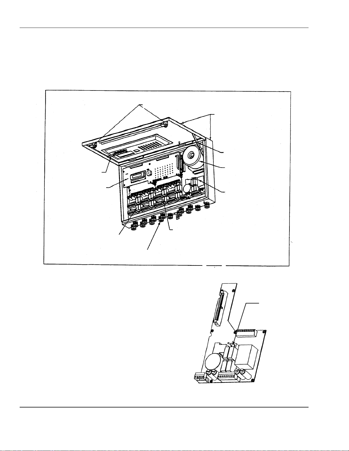
2.1 The wall-mounted enclosure
The enclosure of the MX48 C
pivoted up to access the interior.
For overall dimensions see section 3 installation, Figure 2 exterior view.
For over view of interior see Figure 1 interior view.
ONTROL
is a wall-mounted box consisting of a case and a cover that can be
¼ turn latches, 2 pl
Enclosure
Locking Brace
ONTROL
Keypad
Display Board
Channel 1 – 4 Board
Cable Glands, 15 pl
Figure 1: Interior View of MX48 C
Transformer
Power Supply Board
See Figure 1a
Channel 5 – 8 Board
ONTROL
Switch
Figure 1a: On/Off Switch Power Supply Board
2
Page 7
MX48 C
19.75
″
″
3.75
″
.37
″
17.50″17.50
″
3.56
″
″
″
4.93
″
″
″
″
″
3.0 Installation
3.0 Installation
3.0 Installation3.0 Installation
ONTROL
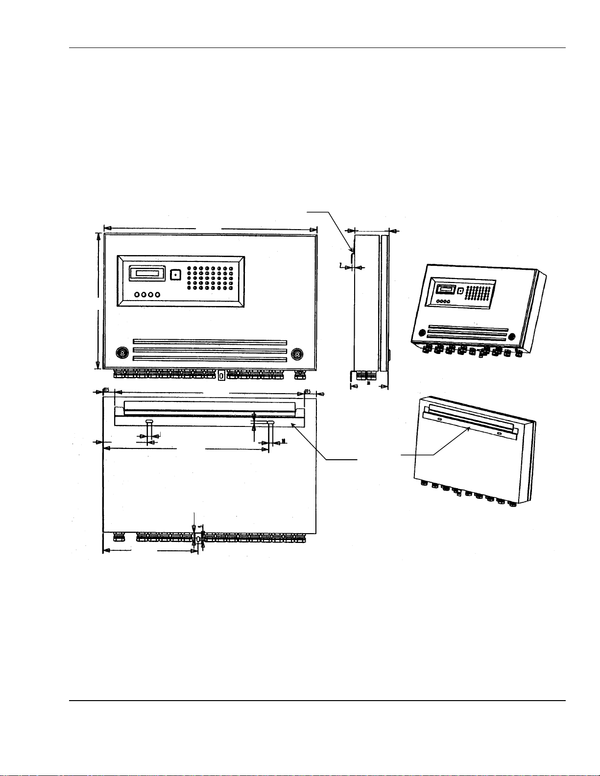
3.1 Installation Recommendations
The MX48 C
in a ventilated area under surveillance such as a, guard post, control room, instrumentation room, etc.
N
OTE
: To be able to fully open the hinged front cover of the MX48 C
The MX48 C
back of the enclosure. See Figure 2
12.50
ONTROL
can be installed anywhere away from an explosive atmosphere. It should preferably be located
cover 90 degrees upwards see Figure 1.
ONTROL
is mounted on the wall with one bracket attached to the wall and the mating bracket is on the
Mounting Bracket
ONTROL
, allow space for opening by rotating the
ENMET Corporation
1.12″
8.87
.62
16.12″16.12
.31
1.12″
.25″.25
.5
1.12″
Figure 2: Mounting MX48 C
Front ViewFront View
Mounting
Bracket
Back View
ONTROL
3
Page 8

ENMET Corporation MX48 C
ONTROL
3.2 Electrical Connection of the MX48 C
To make electrical connections, turn off the control using the general ON/O
ONTROL
FF
switch located on the power supply
board, see Figure 1a for location of ON/OFF switch.
The MX48 C
ONTROL
is equipped with an automatic switching circuit to connect to 24VDC power should the 110V
power fail. Hence, it is possible to use inexpensive backup power supplies.
W
ARNING
:
Continuous gas detection and alarm systems (110VAC/220VAC / 24VDC/12VDC powered) become
inoperative upon loss of primary power. Contact factory for specifications and pricing of backup
battery systems.
3.2.1 AC power supply
Voltage:
Maximum power:
Maximum input current
Cable
Location of connection terminals:
Protection: the phase and neutral wires are protected by time-delay 2A fuses located
Optional Voltage:
110 VAC (103 to 122 V) 50/60 Hz
120 V
AC
2Amp
3 × 1.5 mm2 (earth included)
See Figure 3
on the power supply board
220 VAC (207 to 244 V) 50/60 Hz (optional, must specify when ordering)
AC
C
AUTION
: It is absolutely essential for the MX48 C
within and outside the enclosure. This connection is necessary to ensure the proper operation of
the main power interference suppression filter
the components for protection against electromagnetic interference
3.2.2 DC Supply Input
Voltage:
Maximum power:
Maximum input current
Cable
Location of connection terminals:
Protection:
ONTROL
to be connected to earth ground. Connection is provided
21 to 30 VDC The “minus” of the DC supply is ground and connected to
the chassis.
150 W
6.3 Amp
2 x2.5 mm
2
See Figure 3
There are 2 fuses, (6.3 A) situated on the power supply board
4
Page 9
MX48 C
Connector to
Terminal to
Power On/Off
110V
–24V
I
NPUT
+24V
ONTROL
Display Board
ENMET Corporation
Transformer
Switch
Alarm Relay
Fault Relay
24 VDC Fuses
Clear 1
Clear 2
GND
485-A
485-B
Figure 3: Power Supply Board Connections
DC
DC
I
NPUT
Fault relay
Fault relay
AL3, S
AL3, S
Filter
2A, AC Fuses
AC
Or Optional
NC
YSTEM ALARM RELAY
210VAC if installed
YSTEM ALARM RELAY
5
Page 10
ENMET Corporation MX48 C
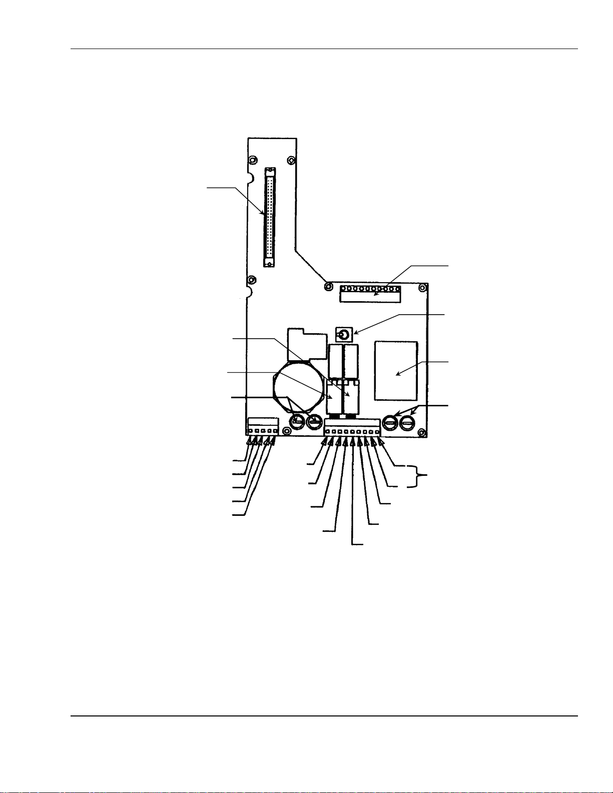
W
ARNING
:
Each channel of the MX48 C
connected. A typical four-channel circuit board is shown in Figure 3a and wiring for this terminal is
shown in Table 3.
ONTROL
has a terminal strip to which all wiring for that channel is
3.2.3 4-20 Sensor/Transmitter
Sensor/Transmitters are connected to positions C1, C2 and C3 on each channel terminal strip. Connections are shown
in Table 1 for two wire S/T and Table 2 for three wire S/T. See Figure 3a for location of channel terminal strips.
Table 1: Wiring for a Two Wire S/T Table 2: Wiring for a Three Wire S/T
Two Wire Sensor/Transmitter Three wire Sensor/Transmitter
C1
C2 Not used C2 Ground
C3 Signal plus, +24VDC power C3 +24VDC power
4-20mA Output Signal
The (+ 4/20 -) positions in each channel terminal is the 4-20mA output from the Control. The plus and minus sides of
the loop are indicated on the terminal strip. See Figure 3a and Table 3.
Signal minus (––––)
3.2.4 Relay Contacts
Auxiliary alarms should be powered from an independent power source separate form the instrument power to avoid
alarm failure due to controller malfunction.
MX48 C
of each channel terminal strip, as indicated in Figure 3a and Table 3. There are 3-pin headers located to the right of the
channel terminals for setting relays to normally open or normally closed operation. To set relays place jumpers in the
position indicated in Figure 3a. These relays have a maximum capacity of 2 Amp at 230 Volts, and are programmed
as described in Section 5.
The system alarm relay contacts AL3 are on the power supply board, as shown in Figure 3.
ONTROL
relay contacts for the first two alarm levels are on the RL, 1, RL and 2 (reference # 6 – 9) positions
C1 Signal
ONTROL
3.2.5 Wiring Requirements
Sensor/Transmitters: Wiring to the Sensor/Transmitters should be by two or three wire shielded cable. The
recommended cable is 18 gauge three wire, ENMET part number 66017-006, Alpha-1747C or
equivalent.
Output Loop: Wiring to output loop should be similar two wire shielded cable.
Relay: Relay wiring can be suitable insulated wire.
Table 3: Typical Channel terminal strip connections
Reference: # Labeled Connection
1 C1 Signal
2 C2 Ground
3 C3
4 + +4-20mA output
5 – –4-20mA output (Ground)
6 RL Alarm 1 relay
7 1 Alarm 1 relay
8 RL Alarm 2 relay
9 2 Alarm 2 relay
+24V
DC
6
Page 11
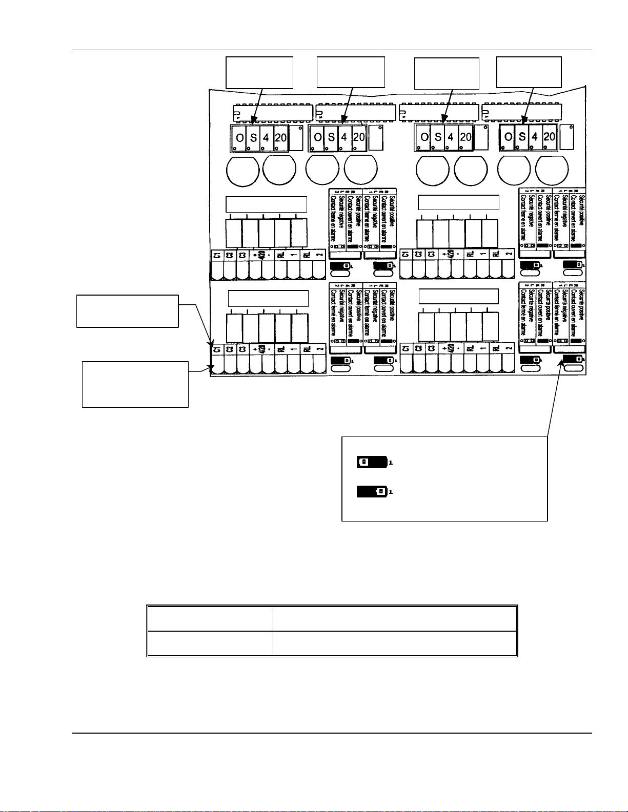
MX48 C
20 =
Fuse
Fuse
Channel Terminal
Channel Terminal
Channel Alarm Relays Jumper Positions
ONTROL
ENMET Corporation
Typical Labeling
Display POTs for
Channel 1 or 5
see Caution
Fuse
Channel 1 or 5
Channel 2 or 6
Display POTs for
Channel 2 or 6
see Caution
Fuse
Fuse
Display POTs for
Channel 3 or 7
see Caution
Fuse Fuse Fuse
Channel 3 or 7
Channel 4 or 8
Display POTs for
Channel 4 or 8
see Caution
2
3 4
1
5
Numbers used as
reference in Table 3
See Figure 1 for location of Channel Boards within
MX48 C
ONTROL
enclosure.
For channels 5 through 8 on second Channel Board:
♦ Channel 1 = Channel 5
♦ Channel 2 = Channel 6
♦ Channel 3 = Channel 7
♦ Channel 4 = Channel 8
Display Potentiometers
Caution:
Each channel display is adjusted at the factory and should not need to be readjusted. Any alignment
should be adjusted at the sensor/transmitter. Table 4 provides the function of MX48 C
potentiometers if adjusted by mistake.
Table 4: Potentiometers per Channel
Left /2 O =
Right /2 4 = potentiometer 4 mA / current output
Control display ZERO potentiometer
S = Control display span potentiometer
potentiometer 20 mA / current output (for full scale)
687
9
Figure 3a: Typical Channel Board
Jumper position on pins 1 & 2
for NC contact (factory setting)
Jumper position on pins 2 & 3
for NO contact
ONTROL
7
Page 12

ENMET Corporation MX48 C
ENMET Corp
*** AUTO TEST***
MX48/52 V2.0r12
4.0 Operation
4.0 Operation
4.0 Operation4.0 Operation
4.1 Checking the Installation
The electrical installation should conform to appropriate electrical codes, such as the National Electrical Code in the
United States.
W
ARNING
:
The compliance of the installation to appropriate codes is not ENMET’s responsibility.
ONTROL
The MX48 C
ONTROL
should be powered through circuit breakers provided for this purpose.
2.2 Turning On the Control
C
AUTION
: The procedures and adjustments described in the following sections must be performed by authorized
personal. Failure to follow instructions may jeopardize accurate measurements.
The MX48 C
• Opening the front cover
• Switching the power ON/OFF switch, located on the power supply board, to the ON position, see Figure 1a.
ONTROL
is tuned on by:
MX48/52 V2.0r12
Example: SETUP Display
The MX48 C
alarms are disabled and the output currents are 1 mA. The MX48 C
all the LEDs. After the minute has elapsed, the active channels go into normal operation and the associated alarms and
relays become effective.
At any time, a manual auto-test can be preformed by pressing the ENTER/TEST button on the keypad located on the
front panel.
This auto-test lasts 30 seconds and the following displays appear alternately:
ENMET Corp
ONTROL
then goes into the SETUP mode for 1 minute. Hence, for those channels which are active all
ONTROL
Then
also performs a auto-test of its buzzer and
MX48/52 V2.0r12
Example: Alternating Auto-test Displays
The auto-test cycle can be interrupted by pressing the CLEAR button on the keypad located on the front panel.
8
Page 13

MX48 C
Buzzer
Front Panel Keypad
Yellow LED
Red LED, AL3
ONTROL
ENMET Corporation
4.3 Operating Modes
4.3.1 Buzzer:
During normal operation, whenever there is a fault or an alarm, the buzzer is triggered. The buzzer is stopped by
pressing the CLEAR button or by clearing remotely. The buzzer emits a continuous sound when an alarm threshold is
exceeded.
4.3.2 Light-emitting Diodes (LED)
Each channel has 5 LEDs that are visible and labeled on the FRONT panel. See Figure 4.
Table 5: Front Panel LED Indications
LED Not Lighted Lighted Flashing
Green
Upper Red
Center Red
Lower Red
Yellow
Channel not in service Channel in service
AL1 not triggered AL1 threshold exceeded, with
automatic cancellation
AL2 not triggered AL2 threshold exceeded, with
automatic cancellation
AL3 not triggered AL3 threshold exceeded on average
or lag, with automatic cancellation
No fault Channel faulty Channel being calibrated or
AL1 threshold exceeded, with manual
cancellation, and not cleared
AL2 threshold exceeded, with manual
cancellation, and not cleared
programmed
4-20mA open (disconnected)
Display
See Figure 4a
¼ Turn Latches 2pl
Figure 4: MX48 C
––––
––––
Previous Next Clear Enter
++++
++++
ONTROL
Front Panel
TEST /
ENTER
Figure 4a: Front Panel Keypad Buttons
Green LED
Red LED, AL1
Red LED, AL2
N
OTE
: In some applications, slight electronic noise between the Sensor/Transmitter and the Control can cause
fluctuations in the display reading. These minor fluctuations are considered to be insignificant in terms of the
range, detection limit and alarm values of the gas being monitored.
9
Page 14

ENMET Corporation MX48 C
Channel 1
4.3.3 Alarm Thresholds
Each of the 3 alarm thresholds can be programmed independently for each channel (see "Channel programming"
menu).
During normal operation a gas alarm is triggered only after a preprogrammed lag time, so as to avoid untimely alarms.
The alarm thresholds can be dealt with in the following ways:
during a normal cycle with manual cancellation
during a normal cycle with automatic cancellation
during a parking cycle
The alarm thresholds are selected based on the detected gases and the corresponding standards in force.
4.3.4 Normal Non-alarm Operation
One minute after turning on and if no test action is performed on the keypad, the control scans all the active channels
in succession and displays the values measured.
For a combustible gas For a toxic gas
Channel 1
XX LEL CH4
Example: Normal Operating Display
Each channel is displayed for 10 seconds.
A channel can be displayed manually by selecting the channel with the + and – buttons. The manual display lasts
for 1 minute.
The Display can return to normal cyclic scanning during this minute, by pressing the + and - buttons
simultaneously. The display then indicates, alternately and 3 times in succession:
Channel 2
XXX ppm CO
ONTROL
For a combustible gas For a toxic gas
Channel 2
XX LEL CH4
N
OTE
: In some applications, slight electronic noise between the Sensor/Transmitter and the Control can cause
fluctuations in the display reading. These minor fluctuations are considered to be insignificant in terms of the
range, detection limit and alarm values of the gas being monitored.
Example: Normal Operating Display
XXX ppm CO
10
Page 15

MX48 C
5.0 Programming
5.0 Programming
5.0 Programming5.0 Programming
ONTROL
Functions of Switches and Menus for Programming and Calibration
5.1 Front Panel Keypad
The keypad is has four pressure switches (buttons) on the MX48 C
ONTROL
ENMET Corporation
FRONT panel.
––––
––––
- Manual display of previous channel
––––
––––
++++
++++
- Manual display of previous menu
- Decrease value, threshold, etc.
- Display of previous choice (on ← off, etc.)
- NO
- Combined with the “PLUS” switch to restart the channel’s automatic display cycle.
- Manual display of next channel
- Manual display of next menu
- Increase value, threshold, etc.
- Display of next choice (on ← off, etc.)
- YES
- Combined with the “MINUS” switch to restart the channel’s automatic display cycle.
++++
++++
TEST /
ENTER
TTEESSTT /
EENNTTEER
- “Audio and visual” or “audio” clearing of an alarm
- Exit from a current menu
/
R
- Start an auto-test manually
- VALIDATE, Enter
11
Page 16

ENMET Corporation MX48 C
Calibration Switch
Channel 5 – 8 Board
Channel 1 – 4 Board
5.2 Maintenance Switches
PROGRAMMING switch: accessible after opening and swiveling the front panel.
Combined with the “–” switch to go back in a menu.
To quit normal display mode and access the various menus (see block diagram of the various menus).
To scroll through a menu.
CALIBRATION switch: accessible after opening and swiveling the front panel.
To set a channel to CALIBRATION mode.
To quit that mode.
See section 5.3.2 for a detailed description of the use for each switch while programming.
Connector to
Connector to
Connector to
Connector to
Power Supply
Power Supply
9 pin DIN
connector
ONTROL
Display
Maintenance Keypad
See Figure5a for details
Programming Switch
Figure 5: Display Board
–
+
ACQUIT
ENTER
Programming Switch
Figure 5a: Maintenance Keypad Switches
Calibration Switch
12
Page 17

MX48 C
Calibration Switch
Channel 5 – 8 Board
ONTROL
ENMET Corporation
5.3 Menus
5.3.1 Menus and their Functions
The MX48 C
These five menus are as follows:
ONTROL
has five menus that are accessed by pressing the “Programming” switch.
Table 6: Programming Functions
DESIGNATION FUNCTION
“CHANNEL” programming - To program the whole configuration of a channel (ON/OFF, range,
alarm thresholds, etc...)
“SIMULATION” programming - To artificially vary a channel measurement on:
- the display panel,
- the 4-20 mA current output.
- To trigger the alarms (LED and relays) at the same time.
“CHANNEL COPY” programming - To copy the complete programming from one channel to another
(time saving)
“CONTROL UNIT” programming
“REPROGRAMMING” programming - To transfer data, measurements and events, etc., from the unit to a
The block diagrams for each of these menus are shown in section 5.4.
- To program the whole configuration of the MX48 C
(language, slave number, etc.).
computer via the MX48 C
ONTROL
RS 485 / J BUS output.
ONTROL
Connector to
Channel 1 – 4 Board
Display
Maintenance Keypad
Connector to
Connector to
Power Supply
9 pin DIN
connector
Programming Switch
Figure 6: Display Board
13
Page 18

ENMET Corporation MX48 C
-
EN TE R
-
-
5.3.2 Legend for Block Diagrams of Programming Menus
It is easy to use these various menus by means of the switches on the keypad and the “Programming” switch
Detailed flow diagrams of the menu scrolling function and of each menu are given in the following sections.
ONTROL
P
+
ACQUIT
P
Programming switch
Switch used to move forward
Switch used to move in reverse
Switch used to enter data
This switch can also be used to exit from the current menu.
When in a menu, you can go back (to make checks or modifications, etc...) by
pressing and holding down switch
Programming switch.
and by successively pressing and releasing the
[ ]
(1) Free This means that the relay can be controlled freely in positive or normal safety mode
Set to
Set to 1
Parameters specified in square brackets [ ] are the VALID parameters (in memory).
(programming by MX48).
This means that the relay will be controlled, set to 0 or 1, and programmed directly via
the J.BUS input and the “
COM
48” software.
14
Page 19

MX48 C
–
+
+
–
–
To program the whole configuration of a channel
See section 5.4.1
To artificially vary a channel measurement on:
See section 5.4.2
To copy the complete programming from one channel to another
MX48 C
To transfer data, measurements and events, etc., from the unit to a
ONTROL
5.4 Bock Diagram of Scrolling Programming Menus
ENMET Corporation
NORMAL
DISPLAY
P
Programming
[Channel xx]
Programming
Simulation [Channel xx]
–
Programming
Copy [Channel xx]
+
See section 4.3.4
(ON/OFF, range, alarm thresholds, etc...)
- the display panel,
- the 4-20 mA current output.
To trigger the alarms (LED and relays) at the same time.
(time saving) See section 5.4.3
Programming
Control Unit
+
Programming
Reprogramming
To program the whole configuration of the
(language, slave number, etc.). See section 5.4.4
computer via the MX48 C
See section 5.4.5
ONTROL
RS 485 / J BUS output.
ONTROL
15
Page 20

ENMET Corporation MX48 C
-
←
+
ENTER
+→+→+→+→+→+
ENTER
+
→
+
→
+
→
+
→
+
→
+
ENTER
+
→
-
ENTER
+
→
-
ENTER
Seuil
Alarme 1
Channel
xx
Measuring range
Decimal point
Alarm 1 threshold
Alarm 2 threshold
5.4.1 Block Diagram of Channel Programming Menu
NORMAL
[25]
DISPLAY
P
ONTROL
Programming
[Channel xx]
P
[Off]
P
[1..]
P
[1…]
: Last channel displayed
: Off On
←
then
←
then
then
→
: Choice of Ranges
10 30 100 300 1000 2000 xxxx U
: Selection of Point Positioning
1. 10.0 1.00 .10 .010 .001
←
←
←
P
[25]
P
[5.]
Continued On Next Page
: . to 2 . . .
←
: . to 2 . . .
←
16
then
then
Page 21

MX48 C
+
←
-
ENTER
-
←
+
ENTER
-
←
+
ENTER
-
←
+
ENTER
-
←
+
ENTER
Alarm 3 threshold
Alarm 2
Alarm 3
Cycle
ONTROL
Continued From Previous Page
P
[75]
P
: . to 2 . . .
→
ENMET Corporation
then
Alarm 1
[Increasing]
P
[Increasing]
P
[Increasing]
P
[Normal]
: Increasing Decreasing
→
: Increasing Decreasing
→
: Increasing Decreasing
→
: Normal Parking
→
then
then
then
then
P
Continued On Next Page
17
Page 22

ENMET Corporation MX48 C
-
←
+
ENTER
-
←
+
ENTER
-
←
+
ENTER
-
←
+
ENTER
-
←
+
ENTER
-
←
+
←
+
ENTER
Ack alarm 1
Alarm 3
Relay safety 1
Ack alarm 2
Relay safety 2
Relay 1
Continued From Previous Page
Manual Automatic
[Manual]
P
[Manual]
P
[Time Lag]
→
Manual Automatic
→
Time Lag Average
→
then
then
then
ONTROL
P
[Positive]
P
[Positive]
P
[Free]
P
Negative Positive
→
Negative Positive
→
Free Set to Strength Set to Preset Relay
→
then
then
→
then
Continued On Next Page
18
Page 23

MX48 C
-
←
+
←
+
ENTER
-
←
+
←
+
ENTER
-
←
+
←
+
ENTER
-
←
+
ENTER
+
←
-
ENTER
-
←
+
←
+
ENTER
Relay 2
Relay 3
Fault relay
Auto Calibration
Channel
xx
Gas
ONTROL
Continued From Previous Page
[Free]
P
[Free]
P
[Free]
P
ENMET Corporation
Free Set to Strength Set to Preset Relay
→
Free Set to Strength Set to Preset Relay
→
Free Set to Set to 1
→
→
→
→
then
then
then
[No]
P
[Premises 1 channel] U
P
[CH4]
P
Continued On Next Page
Flashing
The MX48 C
yellow LED) that a line has-been placed in CALIBRATION
mode on the detector.
No Yes
Free display: A channel heading can be programmed
(in 13 characters maximum). By default, the channel
number is displayed in this area.
CH4 CO 2S etc.
→
→
→
ONTROL
can detect and indicate (with a flashing
then
then
→
then
19
Page 24

ENMET Corporation MX48 C
-
←
+
←
+
ENTER
-
←
+
ENTER
-
←
+
ENTER
-
←
+
ENTER
-
←
+
←
+
ENTER
Units
Alarm time 1
Alarm time 2
H :
mn : sec
Alarm time 3
Sensor type
Continued From Previous Page
LEL % ppm etc.
[LEL]
P
[00:00:05]
H : mn : sec
P
[00:00:05]
→
Time: Time interval between the triggering of the AL LED and
of the corresponding relay, or the minimum operating time of
the relay in parking mode.
→
N
OTE
: Factory default setting is 5 seconds.
Display of time by using switches
→
N
OTE
: Factory default setting is 5 seconds.
→
then
then
then
ONTROL
P
[00:00:05]
H : mn : sec
P
[Flammable]
P
E
ND OF MENU
Text
→
N
OTE
: Factory default setting is 5 seconds.
: Flammable Toxic Spec. toxic
→
then
→
then
20
Page 25

MX48 C
-
←
+
ONTROL
5.4.2 Block Diagram of Simulation Programming Menu
NORMAL
DISPLAY
ENMET Corporation
P
Programming
[Simulation xx]
Programming
[Simulation xx]
Channel xx
+
ENTER
P
LEL CH4 S
Simulation on previously displayed and [validated] channel
Free labeled area
S = flashing to indicate that this channel is in
simulation mode.
→
ACQUIT
E
ND OF MENU
To artificially vary measurement on the display panel, on
the 4-20 mA output, and trigger alarms (LED and relays)
= ESCAPE
To exit from this menu and return to normal operation
21
Page 26

ENMET Corporation MX48 C
-
←
+
5.4.3 Block Diagram of Programming Copy Channel
NORMAL
DISPLAY
ONTROL
P
+ +
Programming
Copy channel xx
ENTER
Programming
[Copy channel xx]
P
Copy channel
[Channel xx => xx]
ENTER
Last channel displayed
Validation of menu
Validation of channel to be copied
: Copy the channel’s configuration to another
channel
xx = indication of “Other channel
number” using keys
→
Copy channel
[Channel xx => xx]
E
ND OF MENU
: Validation of copy
22
Page 27

MX48 C
+
+
ENTER
+→+→+→+
ENTER
+
ENTER
ONTROL
5.4.4 Block Diagram of Programming Control Unit
NORMAL
DISPLAY
ENMET Corporation
P
++ +
Programming
Control Unit
ENTER
Programming
[Control Unit]
P
Language
[English]
P
Validation of menu
Choice of languages:
: French English Espanol
→+→
then
Speed
[96
]
P
Slave address
[1]
P
Continued On Next Page
23
Choice of transmission speed with computer:
12 24 48 96 192 Bauds
then
Choice of slave address (this unit)
to 25
→
then
Page 28

ENMET Corporation MX48 C
-
←
+
ENTER
-
←
+
ENTER
-
←
+
ENTER
-
←
+
ENTER
-
←
+
ENTER
-
←
+
ENTER
Continued From Previous Page
ONTROL
Response time
[00:00:05]
H : mn : sec
P
Stop rL 1&2
[00:00:05]
H : mn : sec
P
Relay safety
[Negative]
P
Buzzer AL.xx
[NO]
P
This is the time interval between exceeding of
the AL threshold and triggering of the
corresponding visual alarm (LED).
Display the time using the switches
→
→ then
→ then
→ then
→ then
→
In “Parking” mode: this is the time interval
between stopping of relay 1 and starting up of
relay 2.
Display the time using switches:
→
Negative Positive
Control of relay 3 (common) by any triggering
of buzzer
NO YES
→
Connected Buzzer
[YES]
P
Continuous buzzer
[YES]
E
ND OF MENU
24
Utilization of common audio alarm (buzzer)?
(Function in series with buzzer jumper)
NO YES
→
YES = Continuous sound
NO = Discontinuous sound
NO YES
→
→ then
→ then
Page 29

MX48 C
ONTROL
5.4.5 Block Diagram of Reprogramming Programming
NORMAL
DISPLAY
ENMET Corporation
P
Press ACQUIT to Escape Mode
If computer is not connected
ACQUIT
++ + +
Programming
Reprogramming
ENTER
Programming
[Reprogramming]
Reprogramming
Confirm
ENTER
Display of menu
Validation of utilization
of menu
Display of menu
confirmation
P
Data transfer request
Validation of data
transfers
E
ND OF MENU
MX48/52 V2.0r12
E
ND OF MENU
25
Confirmation of
uploading
Page 30

ENMET Corporation MX48 C
6.0 WARRANTY
6.0 WARRANTY
6.0 WARRANTY6.0 WARRANTY
ENMET warrants new instruments to be free from defects in workmanship and material under normal use for a period
of one year from date of shipment from ENMET. The warranty covers both parts and labor excluding instrument
calibration and expendable parts such as calibration gas, filters, batteries, etc... Equipment believed to be defective
should be returned to ENMET within the warranty period (transportation prepaid) for inspection. If the evaluation by
ENMET confirms that the product is defective, it will be repaired or replaced at no charge, within the stated
limitations, and returned prepaid to any location in the United States by the most economical means, e.g. Surface
UPS/RPS. If an expedient means of transportation is requested during the warranty period, the customer is responsible
for the difference between the most economical means and the expedient mode. ENMET shall not be liable for any
loss or damage caused by the improper use of the product. The purchaser indemnifies and saves harmless the
company with respect to any loss or damages that may arise through the use by the purchaser or others of this
equipment.
This warranty is expressly given in lieu of all other warranties, either expressed or implied, including that of
merchantability, and all other obligations or liabilities of ENMET which may arise in connection with this equipment.
ENMET neither assumes nor authorizes any representative or other person to assume for it any obligation or liability
other than that which is set forth herein.
NOTE: When returning an instrument to the factory for service:
Be sure to include paperwork.
A purchase order, return address and telephone number will assist in the expedient repair and return of your unit.
Include any specific instructions.
For warranty service, include date of purchase
If you require an estimate, please contact ENMET Corporation.
ONTROL
There are Return for Repair Instructions and Form on the last pages of this manual. This Form can be copied or used
as needed.
Manual Part Number
80003-048
October 1999
MCN-227, 08/15/00
MCN-286, 12/03/02
MCN-359, 06/15/07
26
Page 31

PO Box 979
680 Fairfield Court
Ann Arbor, Michigan 48106-0979
734.761.1270 Fax 734.761.3220
Returning an Instrument for Repair
ENMET instruments may be returned to the factory or any one of our Field Service Centers for regular
repair service or calibration. The ENMET Repair Department and Field Service Centers also perform
warranty service work.
When returning an instrument to the factory or service center for service, paperwork must be included
which contains the following information:
A purchase order number or reference number.
A contact name with return address, telephone and fax numbers
Specific instructions regarding desired service or description
of the problems being encountered.
Date of original purchase and copy of packing slip or invoice
for warranty consideration.
If a price estimate is required, please note it accordingly and be
sure to include a fax number.
Providing the above information assists in the expedient repair and return of your unit.
Failure to provide this information can result in processing delays.
ENMET charges a one hour minimum billing for all approved repairs with additional time billed to the
closest tenth of an hour. All instruments sent to ENMET are subject to a minimum evaluation fee, even
if returned unrepaired. Unclaimed instruments that ENMET has received without appropriate
paperwork or attempts to advise repair costs that have been unanswered, after a period of 60 days,
may be disposed of or returned unrepaired COD with the evaluation fee.
Service centers may have different rates or terms. Be sure to contact them for this information.
Repaired instruments are returned by UPS/FedEx Ground and are not insured unless otherwise
specified. If expedited shipping methods or insurance is required, it must be stated in your
paperwork.
Note: Warranty of customer installed components.
If a component is purchased and installed in the field, and fails within the warranty term, it can
be returned to ENMET and will be replaced, free of charge, per ENMET’s returned goods
procedure.
If the entire instrument is returned to ENMET Corporation with the defective item installed, the
item will be replaced at no cost, but the instrument will be subject to labor charges at half of the
standard rate.
Page 32

Page 33

Repair Return Form
Mailing Address:
ENMET Corporation
PO Box 979
Ann Arbor, Michigan 48106
Phone Number: 734.761.1270
FAX Number: 734.761.3220
Your Mailing Address: Your Shipping Address:
Contact Name: __________________________ Your Phone: _______________________
Your PO/Reference Number: _______________ Your FAX: _______________________
Shipping Address:
ENMET Corporation
Attn: Repair Department
680 Fairfield Court
Ann Arbor, Michigan 48108
Payment Terms: K COD
(Check one) K VISA / MasterCard______________________ ________
Card number Expiration
Return Shipping Method:
K UPS: K Ground K 3 Day Select K Next Day Air K ND Air Saver K 2-Day Air
K Federal Express: K Ground K Express Saver K P-1 K Standard K 2-Day Air
K FedEx Account number: ________________________
Would you like ENMET to insure the return shipment?
K No K Yes Insurance Amount: $_________________
Page 34

 Loading...