

Page 1

ENMET
ENMET Corporation
ENMETENMET
PO Box 979
Ann Arbor, MI 48106-0979
MX32 E
NGUARD
Operation and Maintenance
Manual
Manual Part Number
80003-040
MCN-370, 05/30/07
Page 2

Page 3

Table of Contents
1.0 INTRODUCTION........................................................................................................................................................1
1.1 U
NPACK
......................................................................................................................................................................1
1.2 C
HECK ORDER
1.3 S
ERIAL NUMBERS
2.0 FEATURES..................................................................................................................................................................2
.............................................................................................................................................................1
........................................................................................................................................................1
2.1 MX32 C
2.2 F
ONTROL ELEMENTS
RONT PANEL FEATURES
.........................................................................................................................................2
..............................................................................................................................................3
3.0 INSTALLATION .........................................................................................................................................................5
3.1 M
3.2 W
OUNTING
IRING THE
MX32 C
MX32 C
ONTROL
ONTROL
.......................................................................................................................................5
......................................................................................................................................6
3.2.1 Relay Contacts.....................................................................................................................................................6
3.2.2 Wiring Requirements............................................................................................................................................6
4-20 Sensor/Transmitter................................................................................................................................................8
4.0 OPERATION................................................................................................................................................................9
4.1 F
RONT PANEL PUSHBUTTON SWITCHES
4.2 D
ISPLAY AT START-UP
4.3 D
ISPLAY CYCLE OF CHANNEL MEASUREMENTS
...............................................................................................................................................10
........................................................................................................................9
..........................................................................................................11
4.3.1 Display of No Measurements Mode ....................................................................................................................11
4.3.2 Display of a Single Channel Mode......................................................................................................................11
5.0 MAINTENANCE .......................................................................................................................................................12
5.1 E
NTER THE MAINTENANCE MENUS
..............................................................................................................................12
5.1.1 Entering the Maintenance Menus........................................................................................................................12
5.1.2 Exit the Maintenance Menus...............................................................................................................................12
5.1.3 MX32 C
5.2 P
ROGRAMMING MENU
5.3 I
NITIALIZATION
5.4 C
ALIBRATION MENU
ONTROL
(INI)
Sequence of Maintenance Menus.............................................................................................13
................................................................................................................................................14
MENU
.......................................................................................................................................17
MX32 C
ONTROL
.......................................................................................................................18
5.4.1 Calibration Following an Initialization Non Oxygen Transmitter........................................................................18
5.4.2 Calibration For regular preventive maintenance ................................................................................................19
5.5 C
HANGING ACCESS CODE
5.6 B
UZZER MENU
...........................................................................................................................................................20
..........................................................................................................................................20
6.0 WARRANTY..............................................................................................................................................................21
List of Illustrations
F
IGURE
F
IGURE
F
IGURE
F
IGURE
T
ABLE 1A
F
IGURE
T
ABLE
T
ABLE
T
ABLE
T
ABLE
1: MX32 F
2: MX32 F
3: MX32 D
4: M
: F
5: MX32 C
1:
WIRING TERMINAL
2: W
3: W
4: MX32 C
EATURES
RONT PANEL
ISPLAY
OUNTING
AULT AND ALARM RELAY SETTING
ONTROL MAIN POWER AND CHANNEL BOARD
.................................................................................................................................. 2
............................................................................................................................. 3
..................................................................................................................................... 4
MX32 .................................................................................................................................. 5
........................................................................................................ 6
.................................................................................................................................... 8
IRING FOR A TWO WIRE
IRING FOR A THREE WIRE
ONTROL SEQUENCE OF MAINTENANCE MENUS
S/T.................................................................................................................. 8
S/T............................................................................................................... 8
.............................................................................. 7
.............................................................................13
Page 4

Page 5

MX32 E
1.0 Introduction
1.0 Introduction
1.0 Introduction1.0 Introduction
N
NGUARD
The MX32 C
sensor/transmitter.
The measurement output form the sensor is displayed on the MX32 C
thresholds. If the thresholds are exceeded, the control unit activates audio alarms, visual alarms and relays that may be
used to control external devices.
OTE
: All specifications stated in this manual may change without notice.
ONTROL
unit can monitor one or two independent channels. Each channel is connected to one
ONTROL
unit and compared with preset alarm
ENMET Corporation
1.1 Unpack
Unpack the MX32 C
customer service personnel and the commercial carrier involved immediately.
ONTROL
and examine it for shipping damage. If such damage is observed, notify both ENMET
Regarding Damaged Shipments
N
OTE
: It is your responsibility to follow these instructions. If they are not followed, the carrier will
not honor any claims for damage.
This shipment was carefully inspected, verified and properly packaged at our company and delivered to the
carrier in good condition.
When it was picked up by the carrier at ENMET, it legally became your company’s property.
If your shipment arrives damaged:
• Keep the items, packing material, and carton “As Is.” Within 5 days of receipt, notify the carrier’s local
office and request immediate inspection of the carton and the contents.
• After the inspection and after you have received written acknowledgment of the damage from the carrier,
contact ENMET Customer Service for return authorization and further instructions. Have your Purchase
Order and Sales Order numbers available.
ENMET either repairs or replaces damaged equipment and invoices the carrier to the extent of the liability
coverage, usually $100.00. Repair or replacement charges above that value are your company’s responsibility.
The shipping company may offer optional insurance coverage. ENMET only insures shipments with the
shipping company when asked to do so in writing by our customer. If you need your shipments insured, please
forward a written request to ENMET Customer Service.
Regarding Shortages
If there are any shortages or questions regarding this shipment, please notify ENMET Customer Service within 5 days
of receipt at the following address:
ENMET Corporation
680 Fairfield Court
Ann Arbor, MI 48108
734-761-1270 734-761-3220 Fax
1.2 Check Order
Check, the contents of the shipment against the purchase order. Verify that the MX32
ordered. If there are accessories on the order, ascertain that they are present. Check the contents of calibration kits.
Notify ENMET customer service personnel of any discrepancy immediately.
CONTROL
is received as
1.3 Serial Numbers
Each MX32 C
database.
ONTROL
is serialized. These numbers are on tags on the equipment and are on record in an ENMET
1
Page 6
ENMET Corporation MX32 E
Access Cover
Smoke Grey
2.0 Features
2.0 Features
2.0 Features2.0 Features
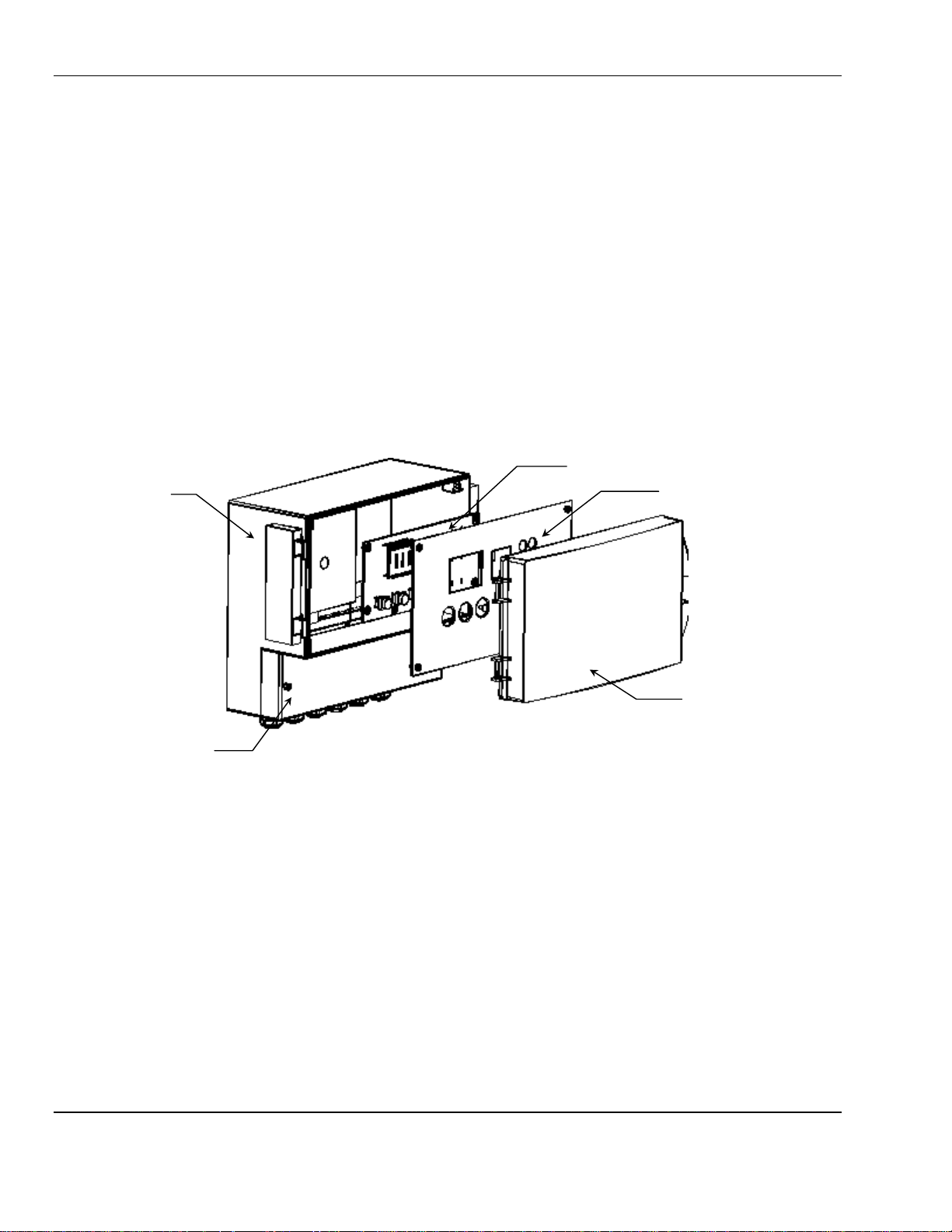
2.1 MX32 Control elements
The MX32 C
Enclosure rated IP 65, NEMA-12, 12K.
Hinged smoke gray viewing cover.
Main power and channel board, that has terminals for power, sensors and relays. Located under access cover.
Display board, attached to front panel.
Front panel with display, alarm LEDs, buzzer (horn) and pushbutton switches.
Enclosure
ONTROL
unit is made up of the following elements:
Display Board
Front Panel
NGUARD
Power, Sensor
and Relay
Terminal
Viewing Cover
Hinged on the
left side
Figure 1: MX32 Features
2
Page 7
MX32 E
Display LCD
Strain Relief
Fault / Calibration /
Channel 2
Alarm 2 LED for
Alarm 1 LED for
each channel
Display / Operation
Front Panel
NGUARD
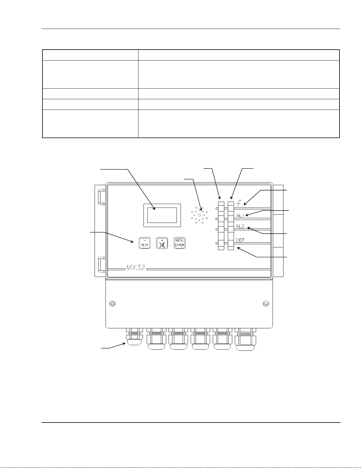
2.2 Front panel features
See Figure 2 for location of features.
LED Description
ENMET Corporation
Display/Operation
[ Lighting bolt on front panel ]
Green LED
When the green LED is blinking the channel is in program mode.
When the green LED is on steady the channel is in operation.
AL1 [ Bell on front panel ] Alarm 1 red LED when in alarm
AL2 [ Bell on front panel ] Alarm 2 red LED when in alarm
Fault / Calibration / Program
[ Wrench on front panel]
Lower most yellow LED
When the yellow LED is on steady, it indicates a malfunction on the line.
When the yellow LED is blinking the channel is in calibration or program mode.
Channel 1 LEDs
See figure 3 for details
Buzzer
LEDs
LED for each channel
Switches
For input cables
each channel
Program LED for
each channel
Figure 2: MX32 Front Panel
3
Page 8
ENMET Corporation MX32 E
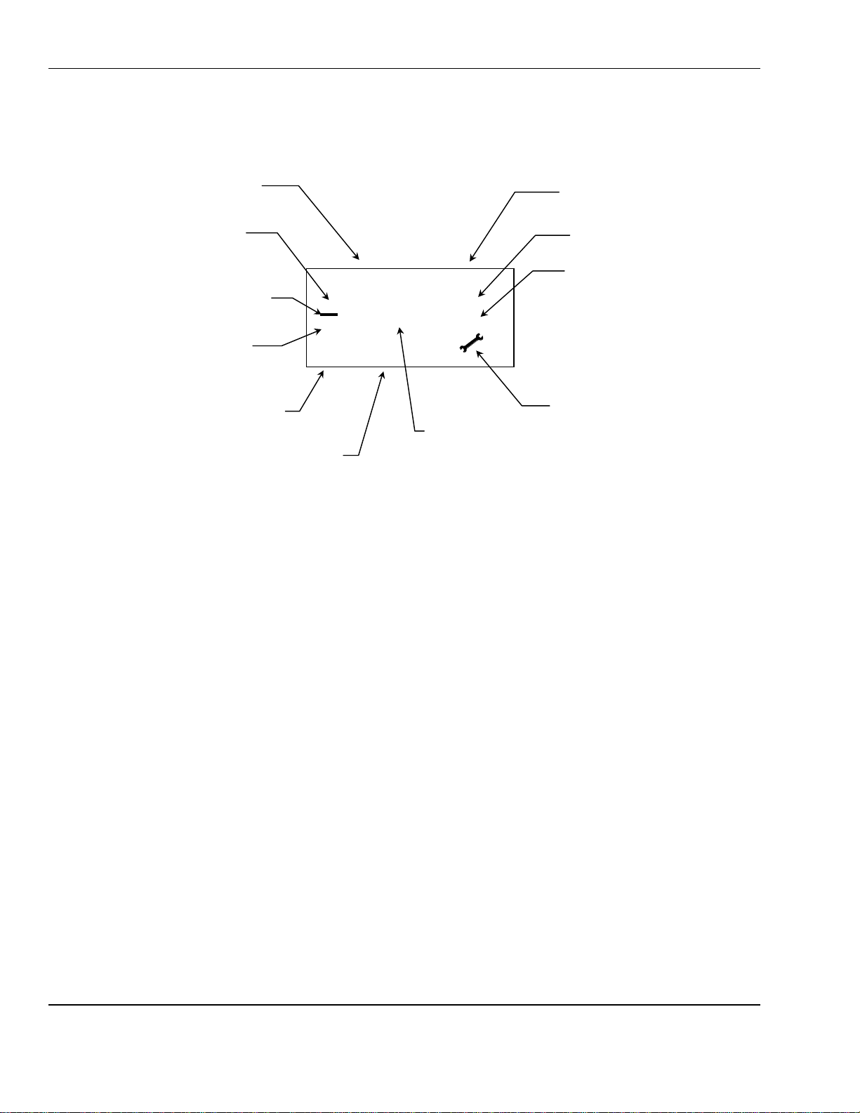
%
Increasing
Indicator
Descending
Indicator
AL1 Alarm
AL 2 Alarm
Smaller Characters for:
Larger Characters for:
NGUARD
Channel 1 Indicator
Value
Negative Sign
Value
indicator
1 2
indicator
8888
HHH
Gas Measurement
Access Code
Maintenance Menus
May display SAVE or ENRG
Channel 2 Indicator
Percent Sign
Gas type
Unit of Measure
Maintenance Menus
May display
YES or OUI
NO or NON
Maintenance Menu Indicator
Figure 3: MX32 Display
N
OTE
: In some applications, slight electronic noise between the Sensor/Transmitter and the Control can cause
fluctuations in the display reading. These minor fluctuations are considered to be insignificant in terms of the
range, detection limit and alarm values of the gas being monitored.
4
Page 9
MX32 E
3.0 Installation
3.0 Installation
3.0 Installation3.0 Installation
NGUARD
The MX32 C
preferably be placed in a ventilated and monitored location, such as guardhouse, control room, instrumentation room,
etc.
N
OTE
: To be able to fully open the hinged front cover of the MX32 C
cover.
ONTROL
can be installed in any indoor area that is not classified a hazardous atmosphere. It should
ONTROL
, allow space for opening the viewing
ENMET Corporation
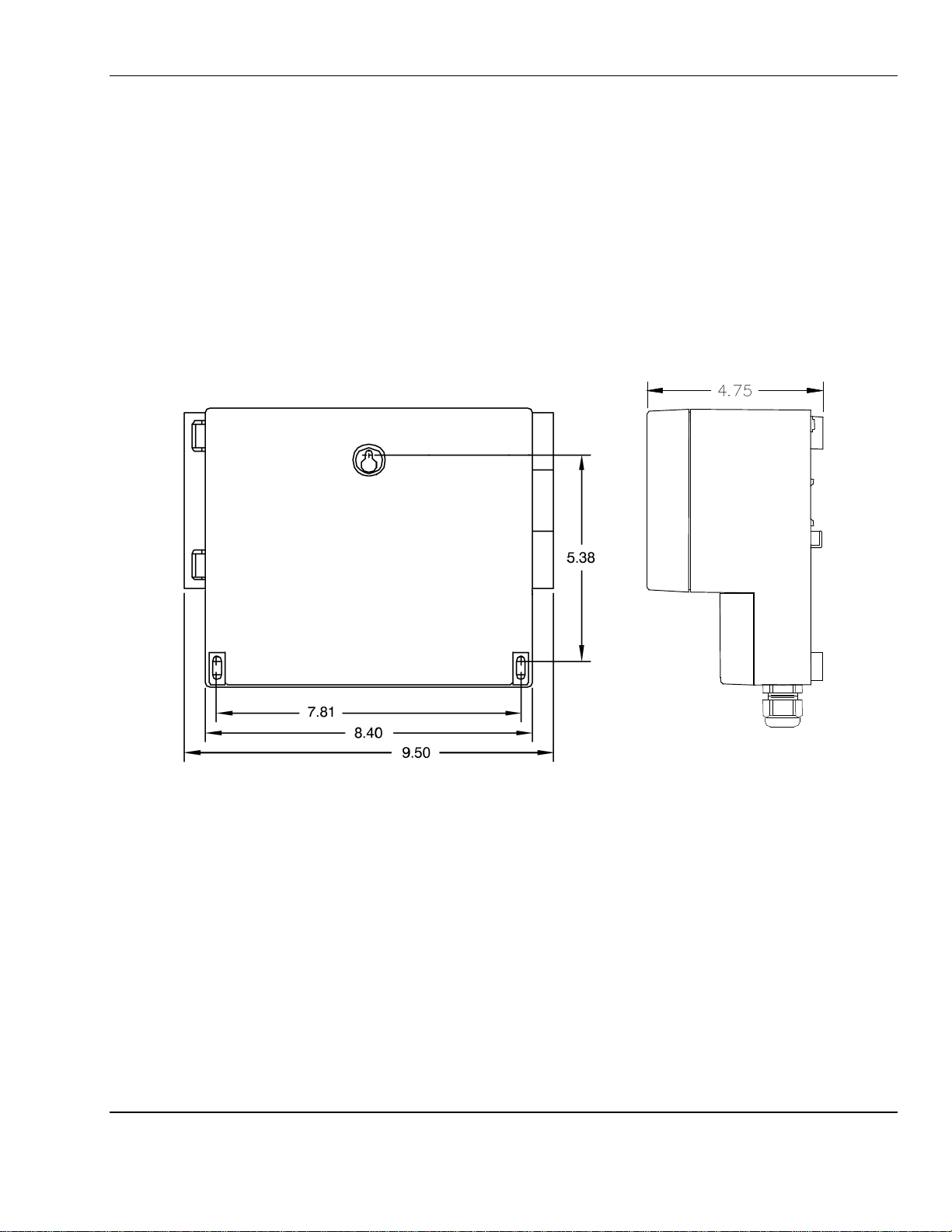
3.1 Mounting MX32 Control
The MX32 C
are also marked on the rear of the enclosure in mm.
ONTROL
is mounted to the wall with 3 screws. Demotions are given in inches in Figure 4. Demotions
Rear View Side View
Figure 4: Mounting MX32
5
Page 10

ENMET Corporation MX32 E
3.2 Wiring the MX32 Control
The electrical installation should conform to appropriate electrical codes, such as the National Electrical Code in the
United States.
W
ARNING
:
The compliance of the installation to appropriate codes is not ENMET’s responsibility.
NGUARD
The MX32 C
W
ARNING
:
Each channel of the MX32 C
two-channel circuit board is shown in Figure 5 and wiring for this terminal is shown in Table 1.
ONTROL
Continuous gas detection and alarm systems (110VAC/220VAC / 24VDC/12VDC powered) become
inoperative upon loss of primary power. Contact factory for specifications and pricing of backup
battery systems.
should be powered through circuit breakers provided for this purpose.
ONTROL
has a terminal strip to which all wiring for that channel is connected. A typical
3.2.1 Relay Contacts
MX32
CONTROL
terminal strip, as indicated in Figure 5 and Table 1. There are 3-pin headers for setting relays to normally open or
normally closed operation. The location of these headers is indicated in Figure 5. To set the relays, place the jumpers
on the position 2 & 3 pins for NO operation or positions 1 & 2 for NC operation. These jumpers are placed in the NC
operation positions at the factory. See Table 1a. These relays have a maximum capacity of 2 Amp at 230 Volts.
The Fault Relay (DEF), system alarm relay contacts are on the main board, as shown in Figure 5.
Auxiliary alarms should be powered from an independent power source separate form the instrument power to avoid
alarm failure due to controller malfunction.
relay contacts for the first two alarm levels are on the RL, 1, RL and 2 positions of each channel
Table 1a: Fault and Alarm Relay Setting
Jumper Position Relay setting
3-pin header
Pin # 1 2 3
2-pin jumper
3-pin header located near associated relay:
Fault relay (DEF) = J103
Channel 1 – AL1 relay = J105, AL2 relay = J101
Channel 2 – AL1 relay = J108, AL2 relay = J107
See Figure 5 for location of each 3-pin header.
Jumper on pins 1 & 2 Jumper on pins 1 and 2 relay NC operation (no power and alarm condition)
(Factory Setting)
Jumper on pins 2 & 3 Jumper on pins 2 and 3 relay NO operation
3.2.2 Wiring Requirements
Sensor/Transmitters:Wiring to the Sensor/Transmitters should be by two or three wire shielded cable. The
recommended cable is 18 gauge three wire, ENMET part number 66017-006, Alpha-1747C or
equivalent.
Output Loop: Wiring to output loop should be similar two wire shielded cable.
Relay: Relay wiring can be suitable insulated wire.
6
Page 11

MX32 E
See Fuse Table
See Fuse Table
J8 J9 J10
POT
channel 1
channel 2
Fault Relay
J110
J105
J11 J12
J13 J14
J15 J16 J17
J18 J19
J20 J21
115 / 220
F7
F9
F11
F13
NGUARD
ENMET Corporation
3-pin header
J103
Fuse 24v
See Fuse Table
Fuse AC
Fuse AC
Input
Input
Input
F8
Figure 5: MX32 C
Fault Relay
DEF
J103
J1 J2 J3 J4 J5
V
AC
J6 J7
ONTROL
Fuse 24v
Output Channel 1
Relay RL2
AL2 Channel 1
Relay RL1
AL1 Channel 1
Sensitivity POT
Sensitivity
Fuse 24v
Output Channel 2
Relay RL2
AL2 Channel 2
Relay RL1
AL1 Channel 2
channel 2
Zero POT
Zero POT
channel 1
Main Power and Channel Board
J107
Ch2, AL2 relay
3-pin header
J108
Ch2, AL1 relay
3-pin header
MX32 C
F7 24v Input
ONTROL
Fuse Table
1.25A Time delay
F9,F8 for 115VAC Input 315mA Time delay
F9,F8 for 230VAC Input 160mA Time delay
F11,F13 24v Output
400mA Time delay
7
Page 12

ENMET Corporation MX32 E
Table 1: wiring terminal
NGUARD
Ref
Label
P J1 Input, AC high
N J2 Input, AC neutral
0 J4 Input, DC minus
+24V J5 Input, DC positive
DEF J6 Fault relay*
C1 J8 Channel 1, Sensor signal – (See Table 2, 3 for 2 or 3 wire S/T)
C2 J9 Channel 1, Sensor ground if used (See Table 2, 3 for 2 or 3 wire S/T)
C3 J10 Channel 1, Sensor + (See Table 2, 3 for 2 or 3 wire S/T)
RL1 J11 Channel 1, Alarm 1 relay*
RL2 J13 Channel 1, Alarm 2 relay*
C1 J15 Channel 2, Sensor signal – (See Table 2, 3 for 2 or 3 wire S/T)
C2 J16 Channel 2, Sensor ground if used (See Table 2, 3 for 2 or 3 wire S/T)
C3 J17 Channel 2, Sensor + (See Table 2, 3 for 2 or 3 wire S/T)
RL1 J18 Channel 2, Alarm 1 relay*
RL2 J20 Channel 2, Alarm 2 relay*
* See Table 1a for setting relays to NO or NC operation.
Terminal
Label
J3 Ground
J7 Fault relay*
J12 Channel 1, Alarm 1 relay*
J14 Channel 1, Alarm 2 relay*
J19 Channel 2, Alarm 1 relay*
J21 Channel 2, Alarm 2 relay*
Wiring
4-20 Sensor/Transmitter
Sensor/Transmitters are connected to positions C1, C2 and C3 on each channel terminal strip. Connections are shown
in Table 2 for two wire S/T and Table 3 for three wire S/T. See Figure 5 for location of channel terminal strips.
Table 2: Wiring for a Two Wire S/T Table 3: Wiring for a Three Wire S/T
Two Wire Sensor/Transmitter Three wire Sensor/Transmitter
C1
C2 Not used C2 Ground
C3 Signal plus, +24VDC power C3 +24VDC power
Signal minus (––––)
8
C1 Signal
Page 13

MX32 E
––––
––––
++++
++++
4.0 Operation
4.0 Operation
4.0 Operation4.0 Operation
NGUARD
The MX32 C
When a visual or audio alarm is activated,
ONTROL
display is independent of the LEDs and relays for each channel.
4.1 Front Panel Pushbutton Switches
Three pressure switches (buttons) on the MX32 C
ENMET Corporation
the display does not automatically display the channel in alarm
ONTROL
FRONT panel.
.
––––
T
TTEESST
++++
MMEENNU
EENNTTEER
––––
T
TTEESST
Manual display of other channel (if 2 channels)
Manual display of previous menu
Decrease value of a digit while setting a value
Combined with “+” switch to step through normal display cycle
Manual display of other channel (if 2 channels)
Manual display of next menu
Increase value of a digit while setting a value
Combined with “–” switch to step through normal display cycle
U
R
To enter maintenance menus
ENTER
++++
MENU
ENTER
9
Page 14

ENMET Corporation MX32 E
4.2 Display at start-up
When power is supplied to the MX32 C
1. Current software version and buzzer test.
Examples of Display:
2. Current menu access code.
Example of Display:
3. Current AL1 threshold displayed for channel 1, while the AL1 and fault light for channel 1 light up.
Example of Display:
ONTROL
120
1270
20
, the unit goes through a self-test sequence as follows:
ver
co
See section 5.0 for Maintenance Menus
Section 5.5 for Access Code
1 0
m32
1
4. Current AL2 threshold displayed for channel 1, while the AL2 and fault light for channel 1 light up.
40
co
Example of Display:
2
5. Current AL1 threshold displayed for channel 2, while the AL1 and fault light for channel 2 light up.
19.5
o2
Example of Display:
1
6. Current AL2 threshold displayed for channel 2, while the AL2 and fault light for channel 2 light up.
23.5
o2
Example of Display:
2
7. Count down (in seconds), time for the sensor(s) to stabilize, and both fault LED are lit.
Example of Display:
0.40
min
This time is programmed at the factory
for best results. See section 5.2 to change
programmed setting.
NGUARD
8. Then the MX32 C
Examples of Display:
ONTROL
will begin the normal display cycle
0
co
10
20.9
o2
See section 4.4 for
Normal Display Cycle
Page 15

MX32 E
NGUARD
ENMET Corporation
4.3 Display Cycle of Channel measurements
C
AUTION
: The display and audio alarms operate independently.
display does not automatically switch to the channel in alarm.
4.3.1 Display of No Measurements Mode
No measurements displayed.
By pressing both the – & + switches at the same time the display changes to no measurement display mode.
Example of the no
measurement Display:
- - - - -
ok
In the no measurement mode to display a channel manually press the + or – switch.
Examples of typical Display:
Press – to display
channel 1 for 1 minute
After about 1 minute, the display returns to the no measurement display mode.
0
co
The display will remain in the no measurement mode
until the + & – switches are pressed at the same time to
change to the single channel display mode.
Examples of typical Display:
Press + to display
channel 2 for 1 minute
4.3.2 Display of a Single Channel Mode
The display will remain in the channel selected by pressing the + or – switch.
By pressing both the – & + switches at the same time a second time, the display changes to a single channel display mode.
By pressing the – switch, the display is manually changed to channel 1 and will continue to display channel 1 until the +
switch is pressed. By pressing the + switch, the display is manually changed to channel 2 and will continue to display
channel 2 until the – switch is pressed.
Examples of typical Display:
Press – to display
channel 1
0
co
Press + to display
channel 2
When an audio and visual alarm are active the
20.9
20.9
o2
o2
To return to the normal display mode press the – and + switches at the same time once more.
11
Page 16

ENMET Corporation MX32 E
5.0 Maintenance
5.0 Maintenance
5.0 Maintenance5.0 Maintenance
The MX32 C
valid access code. The access code is set at the factory and may be changed by following the access code menu
explained in section 5.5.
C
AUTION
See section 4.1 for a description of the pushbutton switches
NOTE: There may be differences in the display for request to save what has been entered in the maintenance menus.
Example:
May display
ENRG or SAVE
ONTROL
: The procedures and adjustments described in the following sections must be performed by authorized
personal. Failure to follow instructions may jeopardize accurate measurements.
unit has 5 maintenance menus that are accessed by pressing the MENU switch and entering a
enrg
oui
Example: May display:
OUI or YES
NON or NO
sa e
yes
5.1 Enter the maintenance menus
When the MENU/ENTER switch is pressed the MX32 C
maintenance portion for programming, initialization, calibration, changing access code and buzzer setting.
If no switch is pressed for one minute, the MX32 C
5.1.1 Entering the Maintenance Menus
To enter the maintenance menus press the MENU/ENTER switch.
If no switch is pressed for one minute, the MX32 C
The request for Access Code display appears. The Access Code set at the factory is 1270.
Example of Displays
The first digit will
be flashing.
0000
cod
To enter the access
code. Press + or – to
select value of digit
ONTROL
ONTROL
ONTROL
unit will request an access code to enter the
will return to normal display mode.
will return to normal display mode.
Press ENTER to move
1000
cod
to next digit.
NGUARD
Press + or – to select
value of digit
Press ENTER to
move to next digit
If the access code is invalid, the display will return to the normal mode.
If the access code is valid, the display will enter the maintenance menus
See Table 4 for the sequence of maintenance menus and a description of their uses. Press the + switch to move to the
next menu or the – switch to move back to the previous menu.
1200
cod
Press + or – to select
value of digit
Press ENTER to move to
next digit
1270
cod
When access code is
complete,
press ENTER.
5.1.2 Exit the Maintenance Menus
To exit the maintenance menus at any point:
Press + & – switches at the same time. The EnrG display will appear.
Press + & – to go
to the save (exit)
display
Press + or – to select OUI (yes) or NON (no). Press ENTER
Press + or – to
select yes or no
The MX32 C
ONTROL
enrg
enrg
will return to the normal display mode.
0
oui
oui
co
12
Page 17

MX32 E
NGUARD
ENMET Corporation
5.1.3 MX32 C
See Table 4 for the sequence of maintenance menus and a description of their uses.
Press the + switch to move to the next menu (↓) or the – switch to move back to the previous menu (↑).
ONTROL
Sequence of Maintenance Menus
Table 4: MX32 Control Sequence of Maintenance Menus
Menu Description Display (flashing)
Access Code
Enter Valid Code ↓
Programming
Press + ↓ or – ↑
Calibration
*
Factory set
Do Not use without
consulting ENMET Corp
Press + ↓ or – ↑
Initialization
*
Factory set
Do Not use without
consulting ENMET Corp
Press + ↓ or – ↑
Access Code Change
Press – ↑
Buzzer
The key used to enter the maintenance
menus.
See section 5.1.1
Used to program the parameters of a
measurement channel. See section 5.2
Used to check and make adjustments to
zero (clean air) and calibration gas.
See section 5.4
Used to initialize the measurement curve
managed by the microprocessor with a
sensor. See section 5.3
Used to change the access code for
entering the maintenance menus.
See section 5.5
Used to set the buzzer active or inactive.
See section 5.6
0000
cod
prg
CAL
ini
%
cod
buz
* C
AUTION
: Do Not enter without first consulting ENMET Corporation.
Improper use will cause the MX32 to be Non-Functional
Use + to by pass this function.
13
Page 18

ENMET Corporation MX32 E
5.2 Programming menu
To set a channel active or inactive, gas to be measured, alarm thresholds, relay timing and sensor type.
See section 5.1.1 to enter a valid access code to enter the maintenance menus. Press the + switch to move through the
maintenance menus until the PRG is flashing.
1. Press ENTER switch while PRG is flashing to enter programming menu
Press ENTER
PRG
The wrench symbol will appear in the lower right corner of the display and the yellow LED of the corresponding
channel is flashing, indicating the MX32 C
2. Select ON or OFF, if the channel is to be active or inactive. The on or off will be flashing.
Press + or – to
select ON or OFF
3. Select the gas to be measured by scrolling through the symbols until the proper symbol appears on the display.
Press + or – to
move through the
symbols
on
Press + or –
to select channel to be
programmed.
ONTROL
CO
is in maintenance mode and the relays are inhibited.
Press ENTER when
correct state is selected
Press ENTER when
correct symbol is
selected
prg
co
ppm
When the channel
indicator is correct,
Press ENTER
Next the symbol for
the gas to be measured
will be flashing
Next the symbol for
the unit of measure
will be flashing
NGUARD
4. Select the symbol for unit of measure by scrolling through the symbols until the proper symbol appears on the display.
1
1
500
35
35
35
Ppm
Ppm
Ppm
Ppm
man
Press ENTER when
correct symbol is
selected
Press ENTER when
correct scale is selected
Press ENTER when
correct decimal place is
selected
Press ENTER when
correct threshold is
selected
Press ENTER when
correct alarm type is
selected
Press + or – to
move through the
symbols
5. For measurement scale Press + to change digit value and ENTER to move to next digit.
Press + or – to
modify the scale
digit by digit
5a. For measurement scale decimal point Press + to change position and ENTER to move to next digit.
Press + or – to
modify the
decimal place
6. This display indicates the Alarm threshold 1 and manual clearance. The red LED for the corresponding alarm is lit.
To modify the alarm threshold AL1 if necessary, Press + to change digit value and ENTER to move to next digit.
Press + or – to
modify the alarm
digit by digit
7. Press + or – to select increasing or decreasing alarm type. Press ENTER
Press + for increasing
Press – for decreasing
N
OTE
: The change may or may not be indicated on the display.
500
1
1
1
35
35
35
man
ppm
man
35
man
man
Next the measurement
scale will be flashing
Next the decimal
placement
Next the AL1
threshold will be
flashing
Next the increasing
decreasing indicator is
flashing
Next the MAN or
AUT is flashing
14
Page 19

MX32 E
NGUARD
Manual alarm clearing: If the gas content drops below the preset alarm threshold again this alarm must be cleared
manually by pressing the + (clear alarm) switch.
Automatic alarm clearing: If the gas content drops below the pre-set alarm threshold again the relay will be
automatically cleared.
8. Press + or – to select manual (MAN) or automatic (AUT) mode for alarm clearing. Press ENTER
Press + or – to
select alarm clear
mode
When the alarm threshold is exceeded the time delay is counted down then the alarms (buzzer and LED) are activated
the relay is activated. Use a 0 min setting for an instantaneous relay activation, this may cause nuisance alarms.
9. Press + or – to select time delay (in minutes) for alarm 1 relay. Press ENTER
Press + or – to
modify the time
digit by digit
10. This display indicates the Alarm threshold 2 and manual clearance. The red LED for the corresponding alarm is lit.
To modify the alarm threshold AL2 if necessary, Press + to change digit value and ENTER to move to next digit.
Press + or – to
modify the alarm
digit by digit
1
00.05
1
35
100
2
MAN
min
Ppm
Press ENTER when
correct alarm clear mode
is selected
Press ENTER when
correct time is selected
Press ENTER when
correct threshold is
selected
00.05
1
100
100
2
2
man
man
man
ENMET Corporation
Next the relay delay
time (in minutes) is
flashing
Next alarm AL2
threshold will be
flashing
Next the increasing
decreasing indicator is
flashing
11. Press + or – to select increasing or decreasing alarm type. Press ENTER
Press + for increasing
Press – for decreasing
N
OTE
: The change may or may not be indicated on the display.
Manual alarm clearing: If the gas content drops below the preset alarm threshold again this alarm must be cleared
Automatic alarm clearing: If the gas content drops below the pre-set alarm threshold again the relay will be
12. Press + or – to select manual (MAN) or automatic (AUT) mode for alarm clearing. Press ENTER
Press + or – to
select alarm clear
mode
When the alarm threshold is exceeded the time delay is counted down then the alarms (buzzer and LED) are activated
the relay is activated. Use a 0 min setting for an instantaneous relay activation, this may cause nuisance alarms.
13. Press + or – to select time delay (in minutes) for alarm 2 relay. Press ENTER
Press + or – to
modify the time
digit by digit
14. Press + or – to select time delay (in minutes) for alarm Fault relay. Press ENTER
Press + or – to
modify the time
digit by digit
100
man
2
manually by pressing the + (clear alarm) switch.
automatically cleared.
100
MAN
2
00.05
00.05
min
2
min
Press ENTER when
correct alarm type is
selected
Press ENTER when
correct alarm clear mode
is selected
Press ENTER when
correct time is selected
Press ENTER when
correct time is selected
00.05
00.05
1.00
100
2
2
man
man
min
min
Next the MAN or
AUT is flashing
Next the relay delay
time (in minutes) is
flashing
Next the fault relay
time delay will be
flashing
Next the stabilization
time count down at start
up will be flashing
15
Page 20

ENMET Corporation MX32 E
15. Press + or – to select the stabilization time at start up. Press ENTER
Press + or – to
modify the time
digit by digit
16. Press + or – to scroll through the different types of sensor if necessary. Press ENTER
Press + or – to
modify the type
See choices below
or AUT = Other, for toxic or Oxygen (for 4-20mA Sensor/Transmitter)
or InC = ionic, optical etc… (not used)
EHP or EHP = Combustible (not used)
or POnt = Bridge (not used)
17. Press + or – to select MAN or AUT. Press ENTER
MAN: no visual alarm, yellow LED flashing, when s/t is in calibration mode
AUT: visual alarm, yellow LED flashing, when s/t is in calibration mode
Press + or – to
select MAN or
AUT
1.00
AUT
AUT
min
man
man
Press ENTER when
correct time is selected
Press ENTER when
correct sensor type is
selected
Press ENTER when
correct choice is selected
auT
auT
0.120
man
man
min
Next the sensor type
will be flashing
May display: OtH
Next the MAN or
AUT will be flashing
Will be displayed
Press ENTER 4 times
NGUARD
enrg
18. Press + or – to select OUI (yes) or NON (no). To update the programming for the channel, Press ENTER
If you select NON and press ENTER the programming will not be updated.
If you select OUI and press ENTER the programming will be updated.
Press + or – to
select yes or no
19. Programming is complete the MX32
enrg
non
oui
Next the save (update)
programming will be
flashing
Press ENTER when
correct choice is selected
CONTROL
display returns to normal display mode.
0
co
Next the MX32
Control returns to the
normal display mode.
16
Page 21

MX32 E
NGUARD
5.3 Initialization (INI) menu
C
AUTION
: This procedure is not used with 4 – 20mA Sensor/Transmitters. Continue to the next
menu.
ENMET Corporation
This menu is used to automatically I
connected to the channel.
Initialization should be done when the unit is first installed and when a cell or sensor is replaced.
See section 5.1.1 to enter a valid access code to enter the maintenance menus. Press the + switch to move through the
maintenance menus until the INI is flashing.
1. Press ENTER switch while INI is flashing to enter initialization menu
Press ENTER
Next the channel indicator is flashing.
2. Press + or – to Select channel to be initialized.
When the channel indicator is correct. Press ENTER
Next the save initialization display is flashing
3. Press + or – to select OUI (yes) or NON (no) for channel initialization to be updated. Press ENTER
Press ENTER
enrg
NITIALIZE
ini
ini
oui
the measurement curve managed by the microprocessor of sensor
4. Initialization is complete the MX32 Control display returns to normal display mode.
0
co
17
Page 22

ENMET Corporation MX32 E
5.4 Calibration Menu MX32 C
C
AUTION
: This procedure is to align the MX32 C
without first consulting ENMET Corporation. Calibration of sensors M
ONTROL
ONTROL
and S/T displays only. Do Not enter
UST
be done at
the sensor/transmitter, in accordance with the S/T manual.
The S/T for Oxygen does not have a zero point. Therefore, a calibration of the S/T in accordance with the S/T manual
should be adequate for alignment.
The MX32 C
of the display compared to the sensor signal.
There are two ways to calibrate the MX32 C
Following an Initialization. See section 5.4.1.
For regular preventive maintenance of unit. See section 5.4.2.
5.4.1 Calibration Following an Initialization Non Oxygen Transmitter
See section 5.1.1 to enter a valid access code to enter the maintenance menus. Press the + switch to move through the
maintenance menus until the CAL is flashing.
1. Press ENTER switch while CAL is flashing to enter the calibration menu.
Press ENTER
2. Apply clean 20.9 oxygen (clean air) to the sensor. Display will show the current zero value, the XO over the
wrench indicates zero adjustment.
3. If necessary (display does not equal Zero) adjust the measurement to Zero by adjusting the Zero Potentiometer
corresponding to the channel concerned. See Figure 5 for location of Zero POT. O = 4mA.
Press ENTER
ONTROL
calibration menu can be used to check and make minor adjustments to the zero and sensitivity
0
ONTROL
cal
Xo
:
Press + or –
to select channel to be
programmed.
CAL
When the channel
indicator is correct,
Press ENTER
NGUARD
4. Apply calibration gas to the sensor and wait until the signal stabilizes. Display will show the current gas
measurement, the XF over the wrench indicates sensitivity adjustment.
W
ARNING
:
Do not make adjustment or press ENTER without applying calibration gas, a fault condition will be triggered.
5. Press ENTER, to indicate
sensitivity adjustment
6. If necessary (display does not equal calibration gas) adjust the measurement to the calibration gas by adjusting the
Sensitivity Potentiometer corresponding to the channel concerned. See Figure 5 for location of Sensitivity POT.
Press ENTER to update
adjustment
Then the request to save calibration is displayed
7. Press + or – to select OUI (yes) or NON (no) for channel calibration to be updated. Press ENTER.
If you select NON and press ENTER the calibration will not be updated.
If you select OUI and press ENTER the calibration will be updated.
Press ENTER
8. Calibration is complete MX32 C
enrg
ONTROL
30
Xf
30
Xf
oui
display returns to normal display mode.
0
co
18
Page 23

MX32 E
NGUARD
ENMET Corporation
5.4.2 Calibration For regular preventive maintenance
C
AUTION
The S/T for Oxygen does not have a zero point. Therefore, a calibration of the S/T in accordance with the S/T manual
should be adequate for alignment.
See section 5.1.1 to enter a valid access code to enter the maintenance menus. Press the + switch to move through the
maintenance menus until the CAL is flashing.
1. Press ENTER switch while CAL is flashing to enter the calibration menu.
2. Apply clean 20.9 oxygen (clean air) to the sensor.
Display will show the current zero value, the XO over the wrench indicates zero adjustment.
3. If necessary (display does not equal Zero) adjust the measurement to Zero by pressing + or – switches until display
shows Zero. Press ENTER.
4. Apply Calibration gas to the sensor and wait until the signal stabilizes
Display will show the current gas measurement, the XF over the wrench indicates sensitivity adjustment.
5. Press ENTER, to indicate sensitivity adjustment
: This procedure is to align the MX32 C
sensors M
Press ENTER
Press ENTER
UST
be done at the sensor/transmitter, in accordance with the S/T manual.
cal
0
Xo
30
Xf
ONTROL
Press + or –
to select channel to be
programmed.
and S/T displays only. Calibration of
CAL
When the channel
indicator is correct,
Press ENTER
6. If necessary (display does not equal Span) adjust the measurement to the Span by pressing + or – switches until
display shows the correct measurement. Press ENTER.
Press ENTER to update adjustment
30
Xf
Then the request to save calibration is displayed
7. Press + or – to select OUI (yes) or NON (no) for channel calibration to be updated. Press ENTER.
If you select NON and press ENTER the calibration will not be updated.
If you select OUI and press ENTER the calibration will be updated.
Press ENTER
8. Calibration is complete MX32 C
enrg
ONTROL
0
oui
display returns to normal display mode.
co
19
Page 24

ENMET Corporation MX32 E
5.5 Changing Access Code
This menu allows MX32 C
See section 5.1.1 to enter a valid access code to enter the maintenance menus. Press the + switch to move through the
maintenance menus until the % COD is flashing.
Press ENTER switch while the % COD is flashing to enter the access code menu.
The current access code is displayed.
1. Press + or – select value of digit, press ENTER to move to next digit. When access code is complete, press ENTER.
Press + or – to select
value of digit
Press ENTER to
move to next digit
Then the request to save new access code is displayed.
2. Press + or – to select OUI (yes) or NON (no). To update the access code, Press ENTER
If you select NON and press ENTER the new access code will not be updated.
If you select OUI and press ENTER the new access code be updated.
Press + or – to
select yes or no
If the access code is invalid, the display will return to the normal mode.
If the access code is valid, the display will enter the maintenance menus
ONTROL
1270
enrg
unit access code to be changed.
Press + or – to select
%
cod
oui
value of digit
Press ENTER to move to
next digit
Press ENTER when
correct choice is selected
8888
0
%
cod
co
When access code is
complete,
press ENTER.
Next the MX32
Control returns to the
normal display mode.
NGUARD
5.6 Buzzer menu
This menu allows MX32 C
See section 5.1.1 to enter a valid access code to enter the maintenance menus. Press the + switch to move through the
maintenance menus until the BUZ is flashing.
1. Press ENTER switch to enter the Buzzer menu.
Press ENTER
2. Press + or – to select ON (buzzer active) or OFF (buzzer is non-active). Press ENTER
Press + or –
to select buzzer
setting
3. Press + or – to select OUI (yes) or NON (no) for buzzer setting to be updated. Press ENTER
If you select NON and press ENTER the buzzer setting will not be updated.
If you select OUI and press ENTER the buzzer setting will be updated.
Press + or – to
select yes or no
4. Buzzer setting is complete, the MX32 C
ONTROL
Yes BUZ
enrg
unit to set the buzzer (horn) active or inactive.
buz
oui
0
co
When the buzzer
setting is correct,
Press ENTER
Press ENTER when
correct choice is selected
ONTROL
display returns to normal display mode.
20
Page 25

MX32 E
6.0 WARRANTY
6.0 WARRANTY
6.0 WARRANTY6.0 WARRANTY
NGUARD
ENMET warrants new instruments to be free from defects in workmanship and material under normal use for a period
of one year from date of shipment from ENMET. The warranty covers both parts and labor excluding instrument
calibration and expendable parts such as calibration gas, filters, batteries, etc... Equipment believed to be defective
should be returned to ENMET within the warranty period (transportation prepaid) for inspection. If the evaluation by
ENMET confirms that the product is defective, it will be repaired or replaced at no charge, within the stated
limitations, and returned prepaid to any location in the United States by the most economical means, e.g. Surface
UPS/FedEx Ground. If an expedient means of transportation is requested during the warranty period, the customer is
responsible for the difference between the most economical means and the expedient mode. ENMET shall not be
liable for any loss or damage caused by the improper use of the product. The purchaser indemnifies and saves
harmless the company with respect to any loss or damages that may arise through the use by the purchaser or others of
this equipment.
This warranty is expressly given in lieu of all other warranties, either expressed or implied, including that of
merchantability, and all other obligations or liabilities of ENMET which may arise in connection with this equipment.
ENMET neither assumes nor authorizes any representative or other person to assume for it any obligation or liability
other than that which is set forth herein.
NOTE: When returning an instrument to the factory for service:
Be sure to include paperwork.
A purchase order, return address and telephone number will assist in the expedient repair and return of your unit.
Include any specific instructions.
For warranty service, include date of purchase
If you require an estimate, please contact ENMET Corporation.
ENMET Corporation
There are Return for Repair Instructions and Form on the last pages of this manual. This Form can be copied or used
as needed.
Manual Part Number
80003-040
February 2001
MCN-271, 01/14/02
MCN-278, 06/07/02
MCN-286, 10/02/02
MCN-328, 03/24/05
MCN-330, 04/01/05
MCN-357, 11/13/06
MCN-370, 05/30/07
21
Page 26

ENMET Corporation MX32 E
Notes:
NGUARD
22
Page 27

PO Box 979
680 Fairfield Court
Ann Arbor, Michigan 48106-0979
734.761.1270 Fax 734.761.3220
Returning an Instrument for Repair
ENMET instruments may be returned to the factory or any one of our Field Service Centers for regular
repair service or calibration. The ENMET Repair Department and Field Service Centers also perform
warranty service work.
When returning an instrument to the factory or service center for service, paperwork must be included
which contains the following information:
A purchase order number or reference number.
A contact name with return address, telephone and fax numbers
Specific instructions regarding desired service or description
of the problems being encountered.
Date of original purchase and copy of packing slip or invoice
for warranty consideration.
If a price estimate is required, please note it accordingly and be
sure to include a fax number.
Providing the above information assists in the expedient repair and return of your unit.
Failure to provide this information can result in processing delays.
ENMET charges a one hour minimum billing for all approved repairs with additional time billed to the
closest tenth of an hour. All instruments sent to ENMET are subject to a minimum $30 evaluation fee,
even if returned unrepaired. Unclaimed instruments that ENMET has received without appropriate
paperwork or attempts to advise repair costs that have been unanswered, after a period of 60 days,
may be disposed of or returned unrepaired COD with the evaluation fee.
Service centers may have different rates or terms. Be sure to contact them for this information.
Repaired instruments are returned by UPS/FedEx Ground and are not insured unless otherwise
specified. If expedited shipping methods or insurance is required, it must be stated in your
paperwork.
Note: Warranty of customer installed components.
If a component is purchased and installed in the field, and fails within the warranty term, it can
be returned to ENMET and will be replaced, free of charge, per ENMET’s returned goods
procedure.
If the entire instrument is returned to ENMET Corporation with the defective item installed, the
item will be replaced at no cost, but the instrument will be subject to labor charges at half of the
standard rate.
Page 28

Page 29

Repair Return Form
Mailing Address:
ENMET Corporation
PO Box 979
Ann Arbor, Michigan 48106
Phone Number: 734.761.1270
FAX Number: 734.761.3220
Your Mailing Address: Your Shipping Address:
Contact Name: __________________________ Your Phone: _______________________
Your PO/Reference Number: _______________ Your FAX: _______________________
Shipping Address:
ENMET Corporation
Attn: Repair Department
680 Fairfield Court
Ann Arbor, Michigan 48108
Payment Terms: COD
(Check one) VISA / MasterCard______________________ ________
Card number Expiration
Return Shipping Method:
UPS: Ground 3 Day Select Next Day Air ND Air Saver 2-Day Air
Federal Express: Ground Express Saver P-1 Standard 2-Day Air
FedEx Account number: ________________________
Would you like ENMET to insure the return shipment?
No Yes Insurance Amount: $_________________
Page 30

 Loading...