

Page 1

ENMET Corporation
PO Box 979
Ann Arbor, MI 48106-0979
MED AIR 2000
Operation and Maintenance
Manual
80002-031
06/03/96
Revised 06/11/97
MCN-167, 09/20/00
MCN-176, 03/06/98
MCN-200, 09/04/98
MCN-204, 01/29/99
MCN-237, 09/21/00
MCN-274, 05/01/02
MCN-327, 02/03/05
MCN-332, 04/15/05
Page 2

Page 3

Table of Contents
1.0 INTRODUCTION ......................................................................................................................................... 1
1.1 Unpack .............................................................................................................................................................1
1.2 Check Order .....................................................................................................................................................1
1.3 Serial Numbers.................................................................................................................................................1
2.0 I
NSTRUMENT FEATURES ............................................................................................................................ 2
2.1 Exterior Features ..............................................................................................................................................2
2.2 Display Panel Features ..................................................................................................................................... 2
2.3 Circuit Board Features......................................................................................................................................4
2.4 Power Supply ...................................................................................................................................................4
2.5 Dew Point Sensor.............................................................................................................................................4
2.6 Dew Point Circuit.............................................................................................................................................4
3.0 I
NSTALLATION .......................................................................................................................................... 5
3.1 Mounting of Instrument....................................................................................................................................5
3.2 Sample Air Supply ...........................................................................................................................................6
3.3 Power Supply ...................................................................................................................................................6
3.4 Outputs .............................................................................................................................................................6
3.4.1 Relay Contacts .......................................................................................................................................6
3.4.2 Optional 4-20mA Outputs ......................................................................................................................7
3.5 Initial Calibration .............................................................................................................................................7
4.0 O
PERATION .............................................................................................................................................. 8
4.1 Normal Operation Condition............................................................................................................................ 8
4.2 Alarm Set Points...............................................................................................................................................8
4.3 Alarm Latching ................................................................................................................................................8
4.4 Audio Defeat ....................................................................................................................................................9
4.5 Display .............................................................................................................................................................9
4.6 Operational Menu.............................................................................................................................................9
4.7 Fault Indications.............................................................................................................................................10
4.7.1 Low Flow Indication ............................................................................................................................10
4.7.2 Other Fault Indications........................................................................................................................10
4.8 Dew Point Sensor Response...........................................................................................................................10
5.0 M
AINTENANCE........................................................................................................................................ 11
5.1 Maintenance Menu.........................................................................................................................................11
5.1.1 Key .......................................................................................................................................................12
5.1.2 Automatic Zeroing................................................................................................................................13
5.1.3 Calibration...........................................................................................................................................14
5.1.4 Select Alarm Set Points ........................................................................................................................15
5.1.5 Set Latches ...........................................................................................................................................16
5.1.6 Set the Key............................................................................................................................................16
5.1.7 Exit .......................................................................................................................................................16
5.2 Sensor Replacement .......................................................................................................................................17
5.2.1 CO Sensor ............................................................................................................................................17
5.2.2 Oxygen Sensor......................................................................................................................................17
5.3 Humidifier Tube.............................................................................................................................................17
5.4 Dew Point Sensor...........................................................................................................................................17
5.5 Flow Control Orifice ...................................................................................................................................... 17
5.6 Particulate Filter Replacement .......................................................................................................................17
6.0 R
EPLACEMENT PART NUMBERS .............................................................................................................. 19
7.0 WARRANTY......................................................................................................................................... 20
A
PPENDIX A ................................................................................................................................................. 21
Page 4

List of Figures and Tables
FIGURE 1: FEATURES OF MED AIR 2000 EXTERNAL................................................................................................ 3
F
IGURE 1A: REGULATOR ....................................................................................................................................... 3
FIGURE 2: MED AIR 2000 INTERIOR FEATURES....................................................................................................... 4
F
IGURE 3: MED AIR 2000 MOUNTING DIMENSIONS ................................................................................................. 5
FIGURE 2A: TERMINAL STRIP................................................................................................................................. 6
ABLE 1: RELAY CONTACTS .................................................................................................................................. 6
T
T
ABLE 2: FAULT RELAY CONTACTS ....................................................................................................................... 7
TABLE 3: OUTPUTS FOR 4-20MA FOR S/N 599 AND BELOW.................................................................................... 7
TABLE 3A: OUTPUTS FOR 4-20MA FOR S/N 600 AND ABOVE.................................................................................. 7
F
IGURE 4: MED AIR 2000 OPERATIONAL DISPLAY.................................................................................................. 8
TABLE 4: FACTORY ALARM SET POINTS................................................................................................................. 8
FIGURE 5: MED AIR 2000 OPERATION MENU FLOW CHART..................................................................................... 9
F
IGURE 6: MED AIR 2000 MAINTENANCE MENU FLOW CHART. ............................................................................. 11
FIGURE 7: CONNECTION OF CALIBRATION GAS CYLINDER..................................................................................... 13
TABLE 5: FAULT ALARM ...................................................................................................................................... 15
F
IGURE 8: REMOVE SHORTING CLIP..................................................................................................................... 18
FIGURE 9: MANIFOLD ........................................................................................................................................... 18
FIGURE 10: LOCATION OF PARTS FO R REPLACEMENT........................................................................................... 18
F
IGURE 11: CARBON MONOXIDE CONCENTRATION ............................................................................................... 21
Reference Information:
N
OTE: [important information about use of instrument]
C
AUTION: [affects equipment – if not followed may cause damage to instrument, sensor etc…]
WARNING: [affects personnel safety – if not followed may cause bodily injury or death.]
Page 5

MED AIR 2000 ENMET Corporation
1.0 Introduction
The MED AIR 2000is a gas and dew point detection instrument that monitors compressed air from medical air supply
systems for certain hazards to the user. The instrument is available with sensors that monitor air for carbon monoxide
(CO), for variations in the oxygen (O
can be used together. In the instrument, a sample of the compressed air is passed over electrochemical CO and O
sensors, a solid state dew point sensor and the resultant electrical outputs are used to evaluate the air for the target
gases. Some features of the instruments are as follows:
continuous monitoring of the sample air
continuous LCD display of gas and vapor concentrations
menu driven operational and maintenance controls
menu driven calibration procedure
audio and visual alarms indicate unsafe conditions
alarm relay contacts available on terminals
a fault relay and visual fault alarm
flowmeter plus low flow fault indication and display
alarm acknowledgement capability including audio defeat
mA outputs for each target gas
NEMA-12 packaging
NOTE: All specifications stated in this manual may change without notice.
1.1 Unpack
Unpack the MED AIR 2000and examine it for shipping damage. If such damage is observed, notify both ENMET customer
service personnel and the commercial carrier involved immediately.
) content and for dew point. The sensors can be used alone or up to three sensors
2
2
Regarding Damaged Shipments
NOTE: It is your responsibility to follow these instructions. If they are not followed, the carrier will
not honor any claims for damage.
This shipment was carefully inspected, verified and properly packaged at our company and delivered to the carrier in good
condition.
When it was picked up by the carrier at ENMET, it legally became your company’s property.
If your shipment arrives damaged:
• Keep the items, packing material, and carton “As Is.” Within 5 days of receipt, notify the carrier’s local office and request
immediate inspection of the carton and the contents.
• After the inspection and after you have received written acknowledgment of the damage from the carrier, contact ENMET
Customer Service for return authorization and further instructions. Have your Purchase Order and Sales Order numbers
available.
ENMET either repairs or replaces damaged equipment and invoices the carrier to the extent of the liability coverage, usually
$100.00. Repair or replacement charges above that value are your company’s responsibility.
The shipping company may offer optional insurance coverage. ENMET only insures shipments with the shipping company
when asked to do so in writing by our customer. If you need your shipments insured, please
ENMET Customer Service.
forward a written request to
Regarding Shortages
If there are any shortages or questions regarding this shipment, please notify ENMET Customer Service within 5 days of receipt at
the following address:
ENMET Corporation
680 Fairfield Court
Ann Arbor, MI 48108
734-761-1270 734-761-3220 Fax
1.2 Check Order
Check, the contents of the shipment against the purchase order. Verify that the MED AIR 2000 is received as ordered. If there are
accessories on the order, ascertain that they are present. Check the contents of calibration kits. Notify ENMET customer service
personnel of any discrepancy immediately.
1.3 Serial Numbers
Each MED AIR 2000 is serialized. These numbers are on tags on the equipment and are on record in an ENMET database.
1
Page 6
ENMET Corporation MED AIR 2000
2.0 Instrument Features
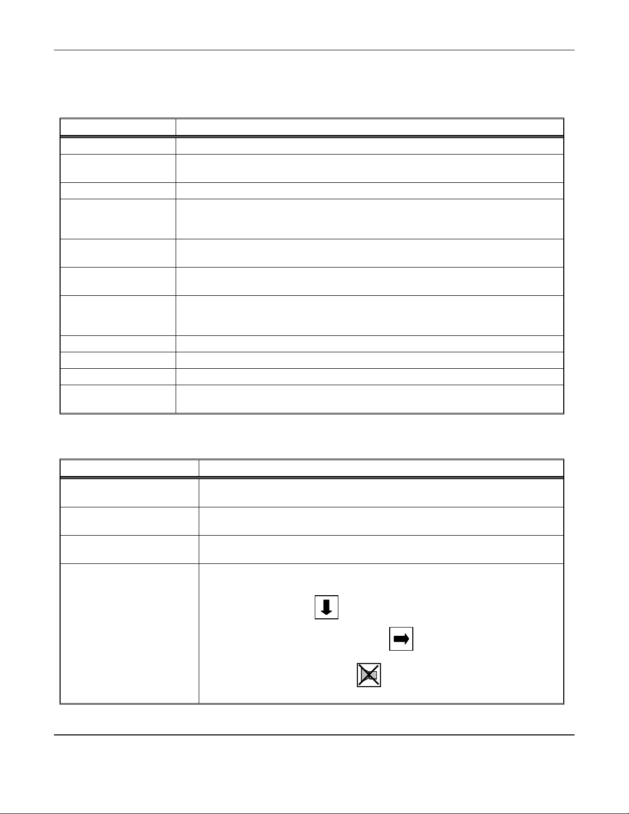
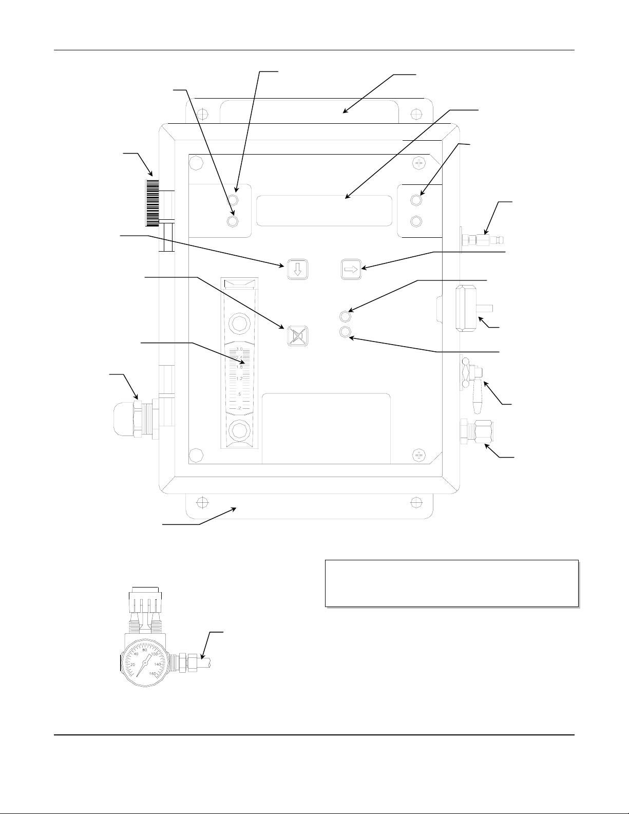
2.1 Exterior Features
The exterior of the instrument is shown in Figure 1. The exterior features are as follows:
Feature Description
Enclosure
Sample Air Hose
Sample Port
Sample/Calibration
Valve
Calibration Port
Front Cover Latch
Humidifier Tube
Line Cord
Audio Alarm
Mounting Flanges
Regulator
(Not supplied)
A NEMA-12 plastic box, approximately 10x8x6, with a clear hinged front cover.
A five foot long hose to conduct a sample of the air from the source to the instrument.
See Figure 1A.
The fitting for the sample air hose.
A red handled ball valve which directs the air from either the sample or the calibrate port.
The handle points at the port, sample or calibrate, which is providing the air to the
instrument
The entrance for the calibration gas. The quick release fitting mates with one on the
calibration adapter.
A quick-release latch that holds the clear front cover in place, and is capable of being
padlocked if desired.
Located under a black sheet metal cover. Is a tube that extracts moisture from the
atmosphere and adds it to dry sample air, before it is presented to the carbon monoxide and
oxygen sensors.
A cord to supply 110 V
A loud horn activated by certain alarm conditions.
Flanges with holes for mounting the enclosure to a vertical surface.
To connect to the compressed air line. Line pressure to the M
55 PSI. See note Figure 1A
AC to the equipment. Not illustrated.
ED AIR 2000 should be set to
2.2 Display Panel Features
The display panel, shown in Figure 1, is viewed through the clear front cover of the enclosure, and is accessed by
opening the cover. Features are as follows:
Feature Description
Display
Flowmeter
Visual Alarms
Pushbutton Switches
•Option Switch
•Select Switch
•Alarm Acknowledge/
Audio Defeat Switch
A 2 line, 16 character per line, LCD with backlight. The numerical values of gas
concentrations, and other information are displayed.
A flow indicator located at the output of the sample flow stream, which indicates
quantitatively the flow of sample air or calibration gas through the instrument.
On both sides of the display, a red LED for each sensor on the instrument.
Near the center of the panel,. a green power LED and a red fault LED,
There are three of these, located near the center of the panel; they are yellow
rectangular membrane switches. They are:
The top left switch.
Directly to the right of the option switch.
Directly under the option switch.
2
Page 7
MED AIR 2000 ENMET Corporation
r
f
p
Visual Alarm
Dew Point
If Dew Point option is installed)
(
Audio Alarm
OPTION
Switch
ALARM ACKNOWLEDGE/
LARM DEFEAT
A
Switch
Flow Mete
Strain Relie
for Line Cord
CO
ppm
Dew
Point
ALARM
ACKNOWLEDGE
Visual Alarm
CO
AUDIO
DEFEAT
SELECTOPTION
POWER
FAULT
Cover, Humidifier Tube
Display
Visual Alarm O2
(If Oxygen option is installed)
O
2
%
Power LED
Calibration
Port
SELECT
Switch
Front Cover Latch
Fault LED
Sample/Calibration
Valve
Mounting Flanges
2 places
Figure 1A: Regulator
Figure 1: Features of MED AIR 2000 External
NOTE: When connecting to a standard 55 PSI USA Medical
air systems, Regulator is Not required.
Regulator is Not supplied by ENMET
Sample Air Hose
to Sam
le Port
3
Sample Port
Input
See note below
Page 8
ENMET Corporation MED AIR 2000
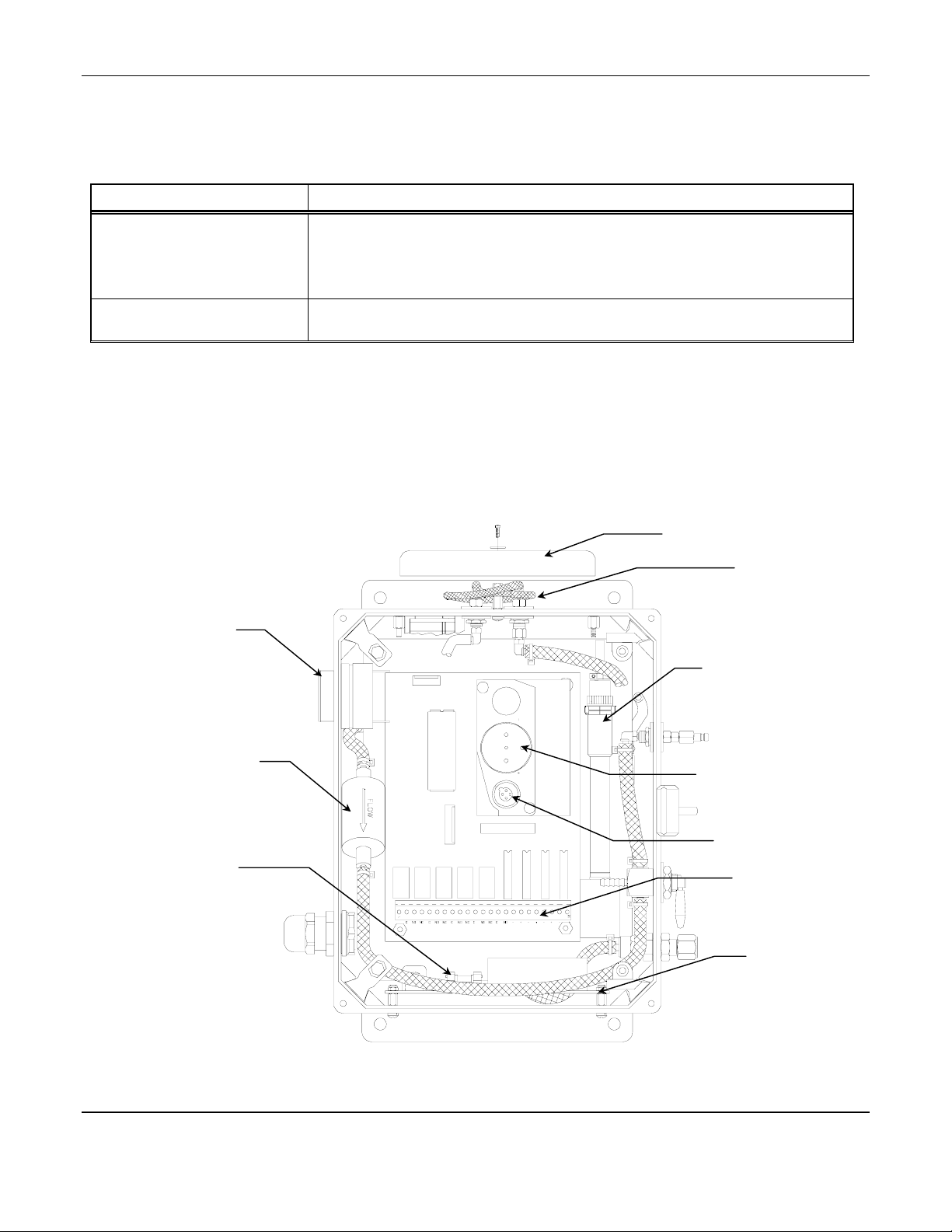
2.3 Circuit Board Features
The Display Panel is hinged on the right and is released by unscrewing the 2 thumb screws located in the left corners.
After releasing the panel, it is swung to the right, exposing the interior of the enclosure. The Circuit Board is mounted
on a plate at the back surface of the enclosure interior. Features are shown in Figure 2.
Feature Description
Terminal Strip
Manifold Housing
This twenty-three position terminal is located at the bottom of the Circuit Board. On
it are twelve positions for three contacts for each of four alarm relays, and three
positions for the contacts of a fault relay.
There are also two positions for each of the 4-20 mA outputs. (optional)
The sample manifold, the carbon monoxide and oxygen sensors are located under
this small aluminum housing. Not illustrated in figure 2, see Figure 8.
2.4 Power Supply
The power supply circuit is located on the bottom surface of the inside of the enclosure. The circuit is protected by
two 1.0 Amp fuses mounted in fuse holders on the power supply board.
2.5 Dew Point Sensor
If present in the instrument, the solid state dew point sensor is located on the plate to the right of the main circuit board.
2.6 Dew Point Circuit
If present in the instrument, the dew point circuit is located on the top surface of the inside of the enclosure.
Cover, Humidifier Tube
Humidifier
Tube
Audio Alarm
Sensor Dew Point
If Dew Point option
is installed
Particulate
Filter
Fuse Holder
Power Supply
PCB
Sensor O2
If Oxygen option is
installed
Sensor CO
Terminal Strip
Power Supply
PCB
Figure 2: MED AIR 2000 Interior Features
4
Page 9
MED AIR 2000 ENMET Corporation
3.0 Installation
3.1 Mounting of Instrument
The MED AIR 2000 should be located near the pipe or tank containing the air to be monitored, and upstream from
where the air is being used. So that, the air sample enters the instrument before it reaches the users.
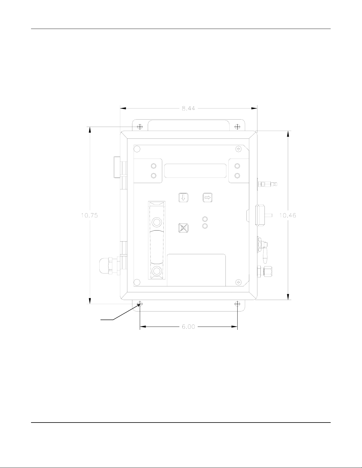
Upright (plumb and level) vertical orientation of the instrument is necessary for proper operation. Mount the
instrument on an appropriate vertical surface using the mounting flanges provided. Avoid areas with excessive
vibration. The holes in the flanges are 0.31 inch in diameter and form a 6 x 10.75 inch rectangle. See Figure 3.
Mounting Holes
0.31” dia. 4 places
Dimensions are in inches.
SELECTOPTION
AUDIO
DEFEAT
ALARM
ACKNOWLEDGE
POWER
FAULT
Figure 3: MED AIR 2000 Mounting Dimensions
5
Page 10

ENMET Corporation MED AIR 2000
3.2 Sample Air Supply
Tap the pipe or tank containing the breathing air and use appropriate fittings to connect the sample input hose. The
instrument is designed to operate from an air supply pressure of 50-55 PSIG; adjust the regulator and set the pressure at
55
PSIG. The flowmeter on the display panel indicates approximately 2 SCFH when the input pressure is 55 PSIG.
The sample air exits the instrument from two separated ports on the back surface of the enclosure. Take care not to
obstruct these exit ports. After mounting the enclosure, they are not accessible.
Be sure that the red sample-calibrate valve handle on the right side of the enclosure is pointed down toward the sample
input port.
3.3 Power Supply
Plug the line cord in a source of 110VAC power. The input power can vary from 100 to 240VAC, 50/60 Hz; if other
than 110 V
Upon supplying air and power to the instrument:
The green power on LED is lit.
The display backlight is lit, and numbers are given on the display.
The instrument may go into alarm briefly, but the sensors stabilize quickly. If the instrument persists in alarm,
acknowledge the alarm by pressing the ALARM ACKN/AUDIO DEFEAT switch. If alarm persists longer than 30
minutes, call ENMET customer service personnel.
AC power is desired, the plug on the line cord must be changed.
3.4 Outputs
Two types of alarm outputs are available, relay contacts and optional 4-20mA outputs.
12 3 4567891011121314151617181920 21 22 23
NC C NO NC C NO NC CNO NC C NO NC CNO G + G + G + G
CO O2 DP N/A Fault LOOP
Figure 2A: Terminal Strip
3.4.1 Relay Contacts
Relay contacts are available for each alarm; these are SPDT, rated at 2.0Amp at 110VAC, and may be latching or nonlatching as required by the application. They are accessed on the terminal strip at the bottom of the circuit board see
Figure 2 & 2A. The positions given in Table 1:
Table 1: Relay Contacts
Position Function Contact
1 CO Alarm NC
2 CO Alarm C
3 CO Alarm NO
4 O2 Alarm* NC
5 O2 Alarm* C
6 O2 Alarm* NO
7 DP Alarm NC
8 DP Alarm C
9 DP Alarm NO
10 Not Used
11 Not Used
12 Not Used
* This relay is activated by both the deficiency and abundance alarms.
These relay coils are energized when they are in the non-alarm state; the contact conditions given above are for the
non-energized state, which is identical to the alarm state.
6
Page 11

MED AIR 2000 ENMET Corporation
In addition, there is a fault relay, which changes state whenever the instrument is in a fault condition.
The contact positions are given in Table 2:
Table 2: Fault Relay Contacts
Position Function Contact
13 Fault NC
14 Fault C
15 Fault NO
The coil of this relay is energized when the instrument is in the non-fault state; the contact conditions given above are
for the non-energized state, which is identical to the fault state.
These relay contacts can be used to operate auxiliary alarms or other functions. Punch a hole at the bottom of the left
side of the enclosure for a wire exit, and use appropriate cable and fittings to preserve the NEMA-12 rating of the
enclosure.
3.4.2 Optional 4-20mA Outputs
Isolated 4-20 mA outputs are available for data logging or other purposes. An output is supplied for each sensor
supplied in a particular instrument, and can be added when a sensor is added in the field. When all three sensors are
supplied, these outputs are available on the terminal strip in the positions given in Table 3:
Table 3: Outputs for 4-20mA for S/N 599 and below
Position Channel Function Range
16 CO Ground 4 mA = 0 ppm
17 CO + 4 to 20 mA 20 mA = 100 ppm
18* DP Ground 4 mA = –100°F
19* DP + 4 to 20 mA 20 mA = +50°F
20* O
21* O
2
2
*When two of the three sensors are supplied, one sensor is for CO, and the output for this sensor is on positions 16
& 17 as shown in Table 3 above. The second output is on positions 20 & 21. Positions 18 & 19 are not used.
Ground 4 mA = 0%
+ 4 to 20 mA 20 mA = 25.5%
Table 3A: Outputs for 4-20mA for S/N 600 and above
Position Channel Function Range
16 CO Ground 4 mA = 0 ppm
17 CO + 4 to 20 mA 20 mA = 100 ppm
18 DP Ground 4 mA = –100°F
19 DP + 4 to 20 mA 20 mA = +50°F
20 O
21 O
2
2
Ground 4 mA = 0%
+ 4 to 20 mA 20 mA = 25.5%
Wiring requirements are the same as for the relays.
3.5 Initial Calibration
All instruments are calibrated at the factory. You may, if a calibration kit is available, calibrate the CO and O
channels of the instrument 24 hours after installation. The dew point sensor can not be calibrated in the field. See
Section 5.0, Maintenance, for calibration instructions. After calibration, be sure to return the red sample-calibrate
valve handle to the down position, pointing toward the sample input port.
7
2
Page 12

ENMET Corporation MED AIR 2000
4.0 Operation
4.1 Normal Operation Condition
With the MED AIR 2000 installed as described in section 3, and in clean air, the POWER green LED is on, the display
is lit, the flowmeter reads approximately 2
for the sensor(s) installed in the M
ED AIR 2000. The red alarm and fault LEDs are not lit.
SCFH, and the information on the display is as shown in Figure 4 Display,
CO
PPM
DEW
POINT
Example of display with Dew Point and Oxygen option installed
000 PPM 20.9%
o
037
F FLOW:y
O
2
%
Figure 4: MED AIR 2000 Operational Display
4.2 Alarm Set Points
There is one alarm set point for CO and dew point, and two for oxygen. The factory settings of these alarm set points
are shown in Table 4.
Table 4: Factory Alarm Set Points
Gas Set Point
Carbon Monoxide 10 ppm
Dew point 39°Fahrenheit at 55PSIG
Oxygen Deficiency 19.5 % by volume
Oxygen Abundance 23.5 % by volume
These alarm set points can be changed within limits; see the maintenance section of this manual for the procedure.
If the CO concentration increases above that of the alarm set point, the associated red LED is lit, the associated
relay changes state, and the audio alarm is activated.
If the dew point increases above that of the alarm set point, the associated red LED is lit, the associated relay
chances state, and the audio alarm is activated.
If the oxygen content of the sample air decreases below the deficiency alarm set point, the associated red LED is
lit, the associated relay chances state, and the audio alarm is activated.
If the oxygen content of the sample air exceeds that of the abundance alarm set point, the associated red LED is lit,
the audio alarm is activated, and both the oxygen alarm relay and the oxygen high alarm relay change state.
There is one alarm LED for both the deficiency and abundance alarms.
4.3 Alarm Latching
An instrument is shipped with the alarms in the non-latching mode. The alarms may be independently configured in
the non-latching mode by use of the maintenance menu.
N THE LATCHING MODE: at the cessation of the condition which causes an alarm, the alarm indications do not
I
cease, and the alarm relay contacts do not revert to the non-alarm state, until the ALARM ACKN/AUDIO
DEFEAT switch is pressed. An alarm can also be acknowledged by pressing the switch during the alarm
condition; then at the cessation of the alarm condition, alarm indications cease and alarm relays revert to the nonalarm state. After an alarm is acknowledged, alarms in the latching configuration are re-armed to latch at the next
alarm condition.
I
N THE NON-LATCHING MODE: at the cessation of the condition which causes an alarm, the alarm indications
automatically cease, and the alarm relay contacts revert to the non-alarm state.
8
Page 13

MED AIR 2000 ENMET Corporation
N
N
N
4.4 Audio Defeat
With the alarms in the non-latching configuration, pressing the ALARM ACKN/AUDIO DEFEAT switch during an
alarm silences the audio alarm.
With an alarm in the latching configuration, pressing the ALARM ACKN/AUDIO DEFEAT switch during an alarm
silences the audio alarm and unlatches the associated relay(s).
4.5 Display
In clean air with the correct dew point, the display is as shown in Figure 4, for the sensor(s) installed in the MED AIR
2000. This position of the display is termed the "operational display". As explained below, the display can be
changed to furnish other information by using the OPTION and SELECT switches.
Concentrations of CO are given in PPM (parts per million parts of air). Dew point is given in degrees Fahrenheit at 55
PSIG; this can be changed to degrees Centigrade by pressing the SELECT switch. Oxygen concentration is given in
per cent by volume. When sample flow is reduced below a limit, the display switches from "Flow: yes" to" Flow: no",
or from "Flow: y" to "Flow: n".
4.6 Operational Menu
The operational menu allows the user to:
View alarm set point concentration values
View alarm latching configurations
Enter the maintenance menu with the proper key.
The operational menu is accessed with the OPTION and SELECT switches. The operational menu flow chart is
shown in Figure 5,
The OPTION switch is indicated with a "O"
The select switch is indicated with a "S".
If the instrument is left at any location in the operational or maintenance menus, other than the operational display,
with no action taken for a period of 45 seconds, it returns to the operational display.
Operational Display
000 PPM 20.9%
037 °FFLOW:y
S
DEW POINT
°C ↔ °F
O
View
Alarms & Latches
O
S
ppm CO: 10
Latch: Yes
O
°F DP: 39.0
Latch: Yes
S
S
o Function
o Function
O
%O2: 19.5 23.5
Latch: Yes Yes
S
o Function
O
run Maintenance
Menu
O
S
To Key
O = Option Switch
S = Select Switch
Figure 5: MED AIR 2000 Operation Menu Flow Chart
9
Page 14

ENMET Corporation MED AIR 2000
4.7 Fault Indications
4.7.1 Low Flow Indication
A sensitive pressure switch is used to furnish a low flow indication. When the sample air pressure drops below
approximately 30
n", depending upon the number of sensors installed in the instrument.
PSIG, the fault light and audio alarm are activated, and the display reads either "Flow: no" or "Flow:
4.7.2 Other Fault Indications
Other fault indications are associated with sensor zero and calibration activities, and are described in the maintenance
section 5.0 of this manual.
4.8 Dew Point Sensor Response
It is a characteristic of this solid state sensor that it takes more time to extract moisture from it by passing dry air over
it, than it does to add moisture to it by passing moist air over it. Therefore, the time response of the sensor to a step
change from moist to dry air is relatively slow, while the response to a step change from dry to moist air is rapid.
10
Page 15

MED AIR 2000 ENMET Corporation
5.0 Maintenance
5.1 Maintenance Menu
The MED AIR 2000 maintenance menu is accessed with the OPTION and SELECT switches. The maintenance menu
diagram is shown in Figure 6 Maintenance Menu Flow Chart. From the operational display, press the OPTION
switch twice; "run MAINTENANCE MODE" is displayed.
Figure 6: MED AIR 2000 Maintenance Menu Flow Chart.
11
O = Option Switch
S = Select Switch
Page 16

ENMET Corporation MED AIR 2000
5.1.1 Key
Entrance to the maintenance menu is guarded with a four-digit key. The factory default setting of the key is 1270.
When a valid numerical key is inserted, the user is allowed to enter the maintenance menu.
In the "run MAINTENANCE MODE" position
Press the SELECT switch; "KEY = 0000" is displayed.
In the "KEY = 0000" position, the underline cursor is under the left digit.
Press the OPTION switch to change the left digit; select the correct digit.
Press the SELECT switch, which locks the correct digit in place and moves the cursor one digit to the right.
Continue this process until the four-digit key is complete. When a valid key is inserted in this manner, the display is
transferred to the "run AUTOMATIC ZEROING" portion of the menu. If an invalid key is inserted, "INVALID" is
displayed briefly; then the M
ED AIR 2000 returns to the operational display.
CO
PPM
DEW
POINT
KEY = 1270
From Operational Menu
To Operational
Display
run MAINTENANCE
O
MODE
Example: Key Display and Flow Chart
S
KEY=0000
Invalid
O
Changes digit indicated by underscore cursor
S
Locks underscore digit and moves cursor to next digit
Valid entry
To Automatic Zeroing
O
2
%
O = Option Switch
S = Select Switch
12
Page 17

MED AIR 2000 ENMET Corporation
E
5.1.2 Automatic Zeroing
A valid key entry sets the instrument in the "run AUTOMATIC ZEROING" position, which enables the setting of the
zero gas concentration point. This is desirable if the zero reference of one of the sensors has drifted over time. For
CO, the zero reference point is 0000 ppm CO; the zero reference point for oxygen is 20.9% oxygen by volume. Note
that the calibration procedure described in section 5.1.3 also includes setting the zero point. If a full calibration is
required, instead of setting just the zero point, press the OPTION switch once; "run FULL CALIBRATION" is
displayed. See section 5.1.3.
T
O SET THE ZERO POINT WITHOUT PERFORMING FULL CALIBRATION:
From the "run AUTOMATIC ZEROING" position, see flow chart.
Press the SELECT button; "ATTACH ZERO GAS" is displayed.
OTE: While it is possible to zero the sensor(s) using a sample from a "clean" air line, this entails using the sample as
N
a standard, and is best avoided. The best zero gas is a cylinder of 20.9% oxygen in nitrogen with no CO
present. This is available in the calibration kit listed in section 6.0
Pressing the OPTION switch at this point aborts the procedure and transfers the display to the "exit MAINTENANCE
MODE" position.
From Valid Key Entry
run AUTOMATIC
ZEROING
S
O
To Full Calibration
Example: Automatic Zeroing Flow Chart
ATTACH
ZERO GAS
S
ZERO=30 .00V
20.9 130 00.0
O
Exit Maintenance Mode
Valid
Invalid
Return to Operational Display
Return to Operational Display with
“Fault 01” in place of the PPM reading
O = Option Switch
S = Select Switch
O CONTINUE THE PROCEDURE: attach a cylinder of zero gas to the Calibration Port using the calibration adapter, as
T
shown in Figure 7. Open the cylinder valve, set the regulator at 55
PSIG, and turn the red handle of the sample-
calibrate valve up toward the calibration port. Let the gas flow for about a minute
Calibration Port
Cylinder Valve
and Regulator
SELECTOPTION
AUDIO
POWER
DEFEAT
ALARM
ACKNOWLEDG
FAULT
Cylinder of Gas
Sample/Calibration
Valve – Up to Calibrate
Figure 7: Connection of Calibration Gas Cylinder
13
Page 18

ENMET Corporation MED AIR 2000
press the SELECT switch.
"ZERO = 30 .00V" is displayed. This is a timer that counts down from 30 seconds, at the end of that time the
procedure is finished. The instrument sets the clean air voltage point for the CO sensor and the 20.9% O
point for
2
the oxygen sensor if it is present. It then examines the validity of these values; if they are valid, it goes back to the
operational display. If a failure occurs, "Fault-01" is displayed in place of PPM reading in the operational display.
FAULT 01 indicates a clean air fault. Verify the proper zero gas is attached to the calibration Port and the samplecalibrate valve is up toward the calibration port. Repeat automatic zeroing procedure. If fault 01 still occurs, replace
sensor in accordance with section 5.2.
After this procedure is complete, be sure to return the red handle of the Sample-Calibrate valve to the down position,
pointing toward the Sample Port. If the Sample-Calibrate valve is not switched back to the sample port, the low flow
fault indication is activated when the zero gas is removed.
5.1.3 Calibration
Insertion of a valid key results in the display: "run AUTOMATIC ZEROING". Press the OPTION switch once; "run
FULL CALIBRATION" is displayed. Press the SELECT switch; "ATTACH ZERO GAS" is displayed; this is the
start of the automatic zeroing procedure as described in paragraph 5.1.2, above. When this procedure is complete,
"ATTACH SPAN GAS - SPAN = 20" is displayed to indicate that the correct span gas for this procedure is 20 ppm
CO in a mixture of 20.9% oxygen in nitrogen. Do Not Use Any Other Than The Correct Span Gas For This
Procedure.
Pressing the OPTION switch at this point aborts the procedure and sets the display at the "exit MAINTENANCE
MODE" position.
From Automatic Zeroing
run FULL
CALIBRATION
O
To Selectable Alarms
S
ATTACH
ZERO GAS
S
ZERO=30 .00V
20.9 130 00.0
S
ATTACH SPAN
GAS PPM CO
S
SPAN=120 .65V
20.9 130 00.0
O
Exit Maintenance Mode
O
Exit Maintenance Mode
Valid
Return to Operational Display
Invalid
Return to Operational Display with
“Fault 01, Fault 02 or Fault 03”
O = Option Switch
S = Select Switch
Example: Full Calibration Flow Chart
T
O CONTINUE THE PROCEDURE:
Attach the correct span gas to the Calibration Port with the calibration adapter turn the red handle of the Sample-
Calibrate valve up toward the Calibration Port. See Figure 7.
Open the cylinder valve, set the regulator at 55
Allow the calibration gas to flow for
AUTION: Pressure fluctuations may lead to aberrant oxygen readings if the SELECT switch is activated in less than
C
at least one minute, then press the SELECT switch.
PSIG.
one minute.
"SPAN = 120 .00V" is displayed. This is a timer that counts down 120 seconds, at that point the procedure is
complete. The “.00V”portion of the display reflects the sensor signal, as it responds to the CO gas. This value
should increase.
After a valid zero and calibration, the instrument reverts to the operational display.
14
Page 19

MED AIR 2000 ENMET Corporation
A
r
y
After an invalid zero or calibration one of the following will be displayed in place of the PPM reading in the
operational display:
Table 5: Fault Alarm
Displayed Cause Possible remedy
• Fault 01
An invalid zero
·verify proper zero gas is attached to calibration port and
sample-calibration valve handle is up
·perform automatic zero
·change sensor in accordance with section 5.2
• Fault 02
An invalid calibration
·verify proper calibration gas is attached to calibration port and
sample-calibration valve handle is up
·perform calibration
·change sensor in accordance with section 5.2
• Fault 03
An invalid zero and
calibration
·verify proper calibration gas is attached to calibration port and
sample-calibration valve handle is up
·perform calibration
·change sensor in accordance with section 5.2
After this procedure is complete, return the red handle of the Sample-Calibrate valve to the down position, pointing
toward the Sample Port. If the Sample-Calibrate valve is not returned to the sample port, the low flow alarm is
activated when the calibration gas is removed.
OTE: During the zero and span process, the sensor singles must fall within a preset limit. If they do not, the fault
N
codes above are generated. If a fault code 02 is generated with calibrating the CO sensor, and the span voltage
is close to, but not greater then 0.38V, an adjustment may be capable of being made, to extend the life of the
sensor. Follow the procedure foe calibrating a sensor as outlined in section 5.2.
5.1.4 Select Alarm Set Points
Factory alarm set points are discussed in paragraph 4.2. To change the alarm set points, after inserting a valid key,
Press the OPTION switch twice; "set SELECTABLE ALARMS" is displayed.
Press the SELECT switch; "ALARM = 0000" is displayed, with the underscore cursor under the left digit.
Press the OPTION switch to change the left digit; select the correct digit.
Press the SELECT switch to lock in the correct digit and move the cursor one digit to the right. When a valid new
alarm is selected, the "NEW = XXXX" is displayed.
Press the OPTION or the SELECT switch, and the display changes to the next sensor. After all sensors have been
displayed, the display returns to the "set SELECTABLE ALARMS" position.
Valid alarm ranges are as follows:
• CO: 5 to 99 ppm
• Dew Point: 0° to 37°C (30° to 98.6°F)
• The Oxygen alarm set points are 19.5% for deficiency and 23.5% for abundance, and are not adjustable.
From Full Calibration
set SELECTABLE
ALARMS
S
set CO Alarm
O
O
To Set Latches
Example: Selectable Alarms Flow Chart
Invalid entr
S
LARM=0000
NEW=0000
Changes digit indicated by
O
underscore curso
S
Locks underscore digit and
moves cursor to next digit
S or O
Exit Maintenance Mode
O = Option Switch
S = Select Switch
15
Page 20

ENMET Corporation MED AIR 2000
5.1.5 Set Latches
To latch and unlatch the alarm relays, after inserting a valid key, press the OPTION switch three times; "set
LATCHES" is displayed.
Press the Select switch; the particular alarm relay and its latch mode is displayed, for example, "RELAY: 10ppm
CO, LATCH: no".
Use the OPTION switch to toggle the latch mode between "yes" and "no". Select the desired mode. See section 4.3.
Press the SELECT switch to step to the next relay. The procedure steps sequentially to all alarm relays in this
manner; when complete, it returns to the "set LATCHES" position.
From Selectable Alarms
set LATCHES
O
S
RELAY 10 PPM CO
LATCH: no
O
Toggles “Yes” and “No”
S
RELAY O2
LATCH: no
O
Toggles “Yes” and “No”
O = Option Switch
S = Select Switch
S
To Set Key
RELAY FAULT
S
LATCH: no
O
Toggles “Yes” and “No”
Example: Set Latches Flow Chart
5.1.6 Set the Key
To set a new key, after inserting a valid key, press the OPTION switch four times; "set KEY” is displayed. Press the
SELECT switch; "KEY = 0000" is displayed, with the underscore cursor under the left digit. Use the OPTION switch
to change the left digit, select the desired digit, and use the SELECT switch to lock the digit in place and move the
cursor one digit to the right. When all four digits of the new key have been selected, "NEW = XXXX" is displayed.
Record the new key; without it, the maintenance menu cannot be reentered once it is left. If the key is lost, call
ENMET customer service personnel.
From the "NEW = XXXX" position, press either the OPTION or the SELECT switch; "exit MAINTENANCE
MODE" is displayed.
From Set Latches
set KEY
S
O
To exit Maintenance Mode
Example: Set Key Flow Chart
KEY=0000
NEW = XXXX
S or O
O
Changes digit indicated by underscore cursor
S
Locks underscore digit and moves cursor to next digit
O = Option Switch
S = Select Switch
5.1.7 Exit
From the "exit MAINTENANCE MODE" position
Press the SELECT switch to resume the operational display.
Press the OPTION switch to reenter the maintenance menu at the "run AUTOMATIC ZEROING" position.
Return to Run Automatic Zeroing
exit MAINTENANCE
MODE
16
SO
Return to Operational Display
Page 21

MED AIR 2000 ENMET Corporation
5.2 Sensor Replacement
5.2.1 CO Sensor
A CO sensor must be replaced when it can no longer be calibrated. To replace a sensor, perform the following steps.
Turn off the electrical power. The sample air can continue to flow.
Open the display panel and remove the two manifold retention screws and remove the manifold. See Figure 9.
Remove the old CO sensor, which is the bottom most sensor, and replace it with a new sensor.
AUTION: New sensors come with a shorting clip that must be removed for proper operation. See Figure 8.
C
Replace the manifold. Observe that the flowmeter reading is correct.
Turn on the electrical power.
Wait 30 minutes, then recalibrate the sensor per the instructions in Section 5.1.3. As the timer is counting down
during calibration, a voltage is displayed on the screen beside the timing count. This voltage must be between:
For Serial No. Range Adjust to
133 and above .38V - .68V .65V
132 and below .59V - .68V .64V
Adjust to: .65V if it is not between .38 – .68V. Adjust this voltage during the last 30 seconds of the calibration
interval, using the bottom most potentiometer on the sensor circuit board. See Figure 10.
Replace the manifold housing, and secure the display panel. An instrument without the manifold housing in place
is susceptible to RFI.
5.2.2 Oxygen Sensor
An oxygen sensor must be replaced when it can no longer be calibrated in clean air. To replace the sensor, follow the
general steps given for the replacement of the CO sensor, but effect a replacement of the oxygen sensor, which is the
large sensor in the center position of the manifold. After sensor installation, wait four hours before recalibrating.
When recalibrating, it is not necessary to make a voltage adjustment.
5.3 Humidifier Tube
The humidifier tube is used to assure that the CO and oxygen sensors are not subjected to extremely dry air for a long
period of time, which would decrease their useful life. Change the humidifier tube when changing a CO sensor at the
completion of its useful life.
To change the humidifier tube:
Remove the sheet metal cover from the top of the enclosure, exposing the humidifier tube. See Figure 10.
Note the coiled arrangement of the tube. Remove the old tube and replace it with the new one.
Replace the sheet metal cover.
5.4 Dew Point Sensor
Unlike the CO and O2 sensors, the dew point sensor cannot be field calibrated. To assure correct performance, the dew
point sensor should be calibrated biyearly. To minimize instrument downtime, take advantage of the dew point sensor
exchange program available through ENMET, in which a year old dew point sensor can be exchanged for a newly
calibrated sensor. Call ENMET customer service personnel for details.
5.5 Flow Control Orifice
A 0.006-inch diameter orifice is used to set the flow rate and to drop the air pressure. It is located where the air enters
the humidifier tube, see Figure 10. In well-maintained medical air systems, this orifice should not clog. However, if
difficulty is experienced in maintaining flow rate with assured inlet pressure, remove air pressure from the equipment
and examine this orifice; replace it if necessary.
5.6 Particulate Filter Replacement
On instruments with serial numbers S/N 332 and above, a filter is installed inside the enclosure, as shown in Figure 10.
To replace this filter:
Obtain a new filter
Note the correct direction of flow, as denoted by the arrow on the filter body
Remove the old filter
Replace with the new filter
17
Page 22

ENMET Corporation MED AIR 2000
Manifold
Sensor
Bottom View
Figure 8: Remove Shorting Clip
Figure 9: Manifold
Cover, Humidifier Tube
Humidifier Tube
Particulate Filter
Flow Control Orifice
Oxygen Sensor
CO Voltage adjustment
Potentiometer
CO Sensor
Figure 10: Location of Parts for Replacement
18
Page 23

MED AIR 2000 ENMET Corporation
6.0 Replacement Part Numbers
ENMET part numbers for replacement parts:
Part number Description
03009-001 Dew Point sensor
05221-001 Power Supply Circuit
64002-1000 Fuse, 1.0 Amp 5x20mm
67016-1106 Sensor, Oxygen
67020-1200 Sensor, CO (for units S/N 299 and below)
67016-1204 Sensor, CO (for units S/N 300 and above)
73070-009 Orifice
73108-002 Humidifier Tube
03401-000 Calibration Kit
03219-020 Gas Cylinder, 20 ppm CO in air
03296-209 Gas Cylinder, 20.9% oxygen in nitrogen
03700-022 Calibration Adapter
73089-002 Filter, particulate (for units S/N 332 and above)
19
Page 24

ENMET Corporation MED AIR 2000
7.0 WARRANTY
ENMET warrants new instruments to be free from defects in workmanship and material under normal use for a period
of one year from date of shipment from ENMET. The warranty covers both parts and labor excluding instrument
calibration and expendable parts such as calibration gas, filters, batteries, etc... Equipment believed to be defective
should be returned to ENMET within the warranty period (transportation prepaid) for inspection. If the evaluation by
ENMET confirms that the product is defective, it will be repaired or replaced at no charge, within the stated
limitations, and returned prepaid to any location in the United States by the most economical means, e.g. Surface
UPS/RPS. If an expedient means of transportation is requested during the warranty period, the customer is responsible
for the difference between the most economical means and the expedient mode. ENMET shall not be liable for any
loss or damage caused by the improper use of the product. The purchaser indemnifies and saves harmless the
company with respect to any loss or damages that may arise through the use by the purchaser or others of this
equipment.
This warranty is expressly given in lieu of all other warranties, either expressed or implied, including that of
merchantability, and all other obligations or liabilities of ENMET which may arise in connection with this equipment.
ENMET neither assumes nor authorizes any representative or other person to assume for it any obligation or liability
other than that which is set forth herein.
NOTE: When returning an instrument to the factory for service:
Be sure to include paperwork.
A purchase order, return address and telephone number will assist in the expedient repair and return of your unit.
Include any specific instructions.
For warranty service, include date of purchase
If you require an estimate, please contact ENMET Corporation.
There is Return for Repair Instructions and Form on the last pages of this manual. This form can be copied or used as
needed.
20
Page 25

MED AIR 2000 ENMET Corporation
Appendix A
The Characteristics and Effects of Carbon Monoxide
Carbon monoxide is a colorless odorless toxic gas generated by incomplete combustion of a hydrocarbon fuel in air. It
may be present where internal combustion engines, furnaces, boilers, and other combustion devices are present. It is
toxic when inhaled because of its great affinity to hemoglobin, the oxygen carriers in the red cells of the blood. CO
replaces the oxygen normally carried by the hemoglobin, and thus inhibits the delivery of oxygen throughout the body;
the victim suffers from oxygen deficiency, and may die from asphyxiation. The symptoms and degree of danger
resulting from exposure to CO depend upon the concentration of the gas and the length of exposure; this is shown in
Figure 8. The M
assessment of the degree of danger that he or she is exposed to.
Based upon knowledge of the effects of CO, the Occupational Safety and Health Authority (OSHA) has set limits on
exposure to CO in the workplace. These are 35 ppm (parts CO per million parts air) as an time weighted average for
an eight hour day, and a maximum exposure of 200 ppm. For compressed air line applications, OSHA requires Grade
D breathing air supplied, using a Compressed Gas Association (CGA) definition (G-7.1). Depending on interpretation
of the OSHA respiratory standard, 10 ppm and 20 ppm CO have been used as maximum limits and standard
instrument alarm points.
The M
ED AIR 2000 has two preset alarm set points, at 10 ppm and 20 ppm CO, which are adjustable, but cannot be set
below 5 ppm or above 100 ppm.
The curves below are for percent carboxalhemoglobin with 50% being the top curve, 5% the bottom. %COHb is a
measure of the amount of hemoglobin occupied by CO rather than oxygen. CO effects upon children, adults engaging
in physical activity, and smokers, are ore pronounced.
ED AIR 2000 instrument is employed to warn the user of the presence of CO, and to facilitate the
Figure 11: Carbon Monoxide Concentration
21
Page 26

ENMET Corporation MED AIR 2000
Notes:
22
Page 27

PO Box 979
680 Fairfield Court
Ann Arbor, Michigan 48106-0979
734.761.1270 Fax 734.761.3220
Returning an Instrument for Repair
ENMET instruments may be returned to the factory or any one of our Field Service Centers for regular
repair service or calibration. The ENMET Repair Department and Field Service Centers also perform
warranty service work.
When returning an instrument to the factory or service center for service, paperwork must be included
which contains the following information:
¾ A purchase order number or reference number.
¾ A contact name with return address, telephone and fax numbers
¾ Specific instructions regarding desired service or description
of the problems being encountered.
¾ Date of original purchase and copy of packing slip or invoice
for warranty consideration.
¾ If a price estimate is required, please note it accordingly and be
sure to include a fax number.
Providing the above information assists in the expedient repair and return of your unit.
Failure to provide this information can result in processing delays.
ENMET charges a one hour minimum billing for all approved repairs with additional time billed to the
closest tenth of an hour. All instruments sent to ENMET are subject to a minimum $30 evaluation fee,
even if returned unrepaired. Unclaimed instruments that ENMET has received without appropriate
paperwork or attempts to advise repair costs that have been unanswered, after a period of 60 days,
may be disposed of or returned unrepaired COD with the evaluation fee.
Service centers may have different rates or terms. Be sure to contact them for this information.
Repaired instruments are returned by UPS/RPS surface and are not insured unless
otherwise specified. If expedited shipping methods or insurance is required, it must be
stated in your paperwork.
Note: Warranty of customer installed components.
If a component is purchased and installed in the field, and fails within the warranty term, it can
be returned to ENMET and will be replaced, free of charge, per ENMET’s returned goods
procedure.
If the entire instrument is returned to ENMET Corporation with the defective item installed, the
item will be replaced at no cost, but the instrument will be subject to labor charges at half of the
standard rate.
Page 28

Page 29

Repair Return Form
Mailing Address:
ENMET Corporation
PO Box 979
Ann Arbor, Michigan 48106
Phone Number: 734.761.1270
FAX Number: 734.761.3220
Your Mailing Address:
Contact Name: __________________________ Your Phone: _______________________
Your PO/Reference Number: _______________ Your FAX: _______________________
Shipping Address:
ENMET Corporation
Attn: Repair Department
680 Fairfield Court
Ann Arbor, Michigan 48108
Your Shipping Address:
Payment Terms: T COD
(Check one) T VISA / MasterCard______________________ ________
Card number Expiration
Return Shipping Method:
T UPS/RPS Surface: T 3 day T 2nd Day Air T Next Day Air
T Federal Express: T Next Day Morning T Next Day AfternoonT Standard
T FedEx Account number: ________________________
Would you like ENMET to insure the return shipment?
T No T Yes Insurance Amount: $_________________
Page 30

 Loading...