

Page 1
ENMET
680 Fairfield Court
LC-Series Controller
Ann Arbor, MI 48108
734.761.1270 Fax 734.761.3220
www.enmet.com
1-4 Channel
Operation and Maintenance Manual
Page 2

LC-Series Controller: 1-4 Channel
ENMET
Manual Revi s i on Date – June 13, 2017
Page | 1
Manual Part No. – 80003-050
!
Table of Contents
1.0 INTRODUCTION .................................................................................................................................................................... 2
1.1 Unpack ............................................................................................................................................................................................. 2
1.2 Check Order ..................................................................................................................................................................................... 2
1.3 Serial Numbers................................................................................................................................................................................. 2
2.0 FEATURES ........................................................................................................................................................................... 3
2.1 Front panel features .......................................................................................................................................................................... 3
3.0 INSTALLATION ..................................................................................................................................................................... 4
4.0 WIRING THE LC SERIES ....................................................................................................................................................... 6
4.1 System Wiring ................................................................................................................................................................................. 6
4.1.1 Power Supply Module ..................................................................................................................................................................................... 7
4.1.3 Connections L C1............................................................................................................................................................................................. 8
4.1.4 Connections L C2............................................................................................................................................................................................. 9
4.1.5 Connections L C4........................................................................................................................................................................................... 10
4.2 Sensor Transmitter Installation ...................................................................................................................................................... 11
4.2.1 Example 2 Wire Sensor Transmitter ............................................................................................................................................................. 11
4.2.2 Example 3 Wire Sensor Transmitter ............................................................................................................................................................. 11
5.0 OPERATION ....................................................................................................................................................................... 12
5.1 LC-Series Microcontroller Module ................................................................................................................................................ 12
5.2 Analogue Output Configuration ..................................................................................................................................................... 14
5.2.1 4-20mA Current Source ................................................................................................................................................................................ 14
5.2.2 4-20mA Current Sink .................................................................................................................................................................................... 15
5.2.3 1-5V Voltage Output ..................................................................................................................................................................................... 16
6.0 MAINTENANCE .................................................................................................................................................................. 17
7.0 TECHNICAL DATA AND SPECIFICATIONS ............................................................................................................................. 18
8.0 TERMS AND CONDITIONS ................................................................................................................................................... 21
8.1 Ordering Information ..................................................................................................................................................................... 21
8.2 Delivery ......................................................................................................................................................................................... 21
8.3 Payment Terms .............................................................................................................................................................................. 21
8.4 Warranty Information and Guidelines ........................................................................................................................................... 21
8.5 Return Policy ................................................................................................................................................................................. 21
9.0 INSTRUCTIONS FOR RETURNING AN INSTRUM ENT FOR SERVICE ........................................................................................... 22
List of Figures
Figure 1: LC Series Front Panel Features .................................................................................................................................................. 3
Figure 2: Mounting LC Series ................................................................................................................................................................... 5
Reference Information:
NOTE: [important information about use of instrument]
AUTION: [affects equipment – if not followed may cause damage to instrument, sensor etc.…]
C
ARNING: [affects personnel sa fe ty – if not followed may cause bodily injury or death.]
W
Attention / Warning
Earth Ground
Page 3

LC-Series Controller: 1-4 Channel
ENMET
Manual Revi s i on Date – June 13, 2017
Page | 2
Manual Part No. – 80003-050
1.0 Introduction
The LC Series Cont rol Units that provide facilities to monitor a wide variety of industry standard environme ntal a nd other sensors.
The LC1 provides 1 monitoring channel.
The LC2 provides up to 2 monitoring channels.
The LC4 provides up to 4 monitoring channels.
The LC-Series Controller has been designed to allow the use of any ENMET sensor transmitter and has been preprogrammed to
match the sensor transmitters supplie d at time of delivery. The LC-Series can also be used with any manufactures sensor transmitter
that can produce a voltage or current output within a specified range; however, it is advisable that you contact ENMET for proper
setup and programming instructions. Care has been taken with the design of the MCU housings and internal chassis to facilitate ease
of connection and wire termination. All on-site wiring to the system is via screw terminal connectors. The terminal cover has an
internal label giving details of the external connections.
OTE: All specifications stated in this manual may change without notice.
N
1.1 Unpack
Unpack the LC-Series Controller and exa mine it for shipping da mage. If such damage is observed, notify both ENMET
customer service personnel and the commercial carrier involved immediately.
Regarding Damaged Shipments
OTE: It is your responsibility to follow these instructions. If they are not followed, the carrier will not honor any claims for
N
damage.
This shipment was carefully inspected, verified and properly packaged at ENMET and delivered to the carrier in good
condition.
When it was picked up by the carrier at ENMET, it legally became your company’s property.
If your shipment arrives damaged :
Keep the items, packing material, and carton “As Is.” Within 5 days of receipt, notify the carrier’s local office and
request immediate inspection of t he carton and the contents.
After the inspection and after you have received written acknowledgment of the damage from the carrier, contact
ENMET Customer Service for return authorization and further instructions. P le a se have your Purchase Order and Sales
Order numbers available.
ENMET either repairs or replaces damaged equipment and invoices the carrier to the extent of the liability coverage, usually
$100.00. Repair or replacement charges above that value are your company’s responsibility.
The shipping company may offer optional insurance coverage. ENMET only ins ures shipments with t he shipping company
when asked to do so in writing by our customer. If you need your shipments insured, please forward a written request to
ENMET Custo me r Service.
Regarding Shortages
If there are any shortages or questions regarding this shipment, please notify ENMET Customer Service within 5 days of receipt at
the following address:
ENMET
680 Fairfield Court
Ann Arbor, MI 48108
734-761-1270 Fax 734-761-3220
Toll Free: 800-521-2978
1.2 Check Order
Check, the contents of the shipme nt against t he purchase order. Verify that the LC-Series Controller is received as ordered. If
there are accessories on the order, ascertain that they are present. Check the contents of calibration kits. Notify ENMET customer
service personnel of any discrepancy immediately.
1.3 Serial Numbers
Each LC-Series Controller is serialized. These numbers are on tags on the equipment and are on record in an ENMET database.
Page 4
LC-Series Controller: 1-4 Channel
ENMET
Manual Revi s i on Date – June 13, 2017
Page | 3
Manual Part No. – 80003-050
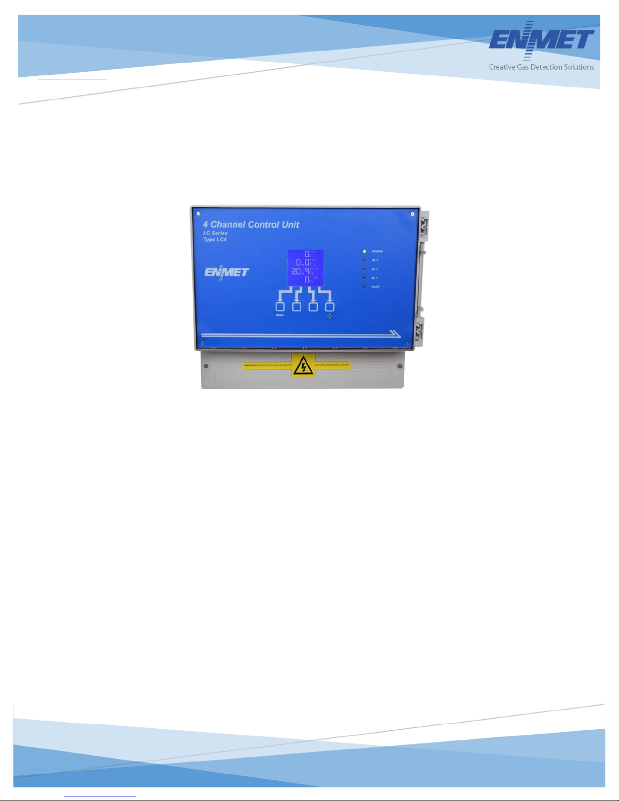
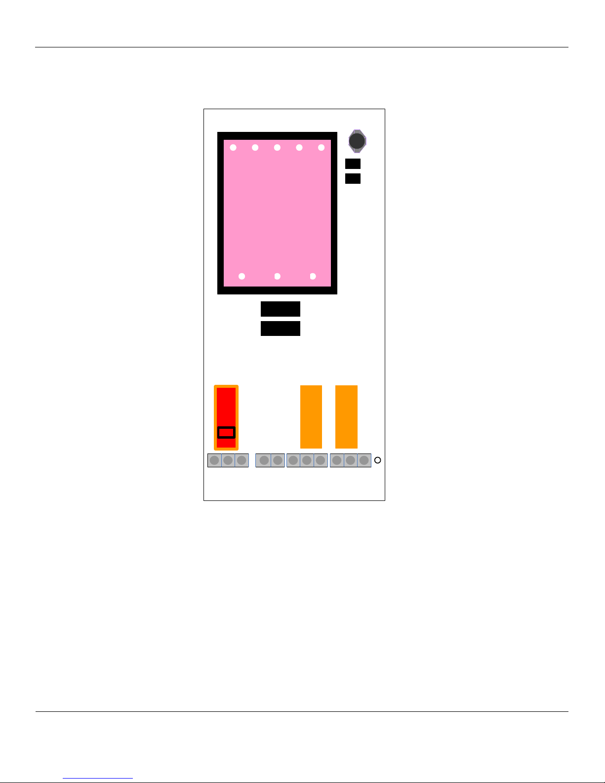
LED
Description
Power
Green LED for Power
AL3
Red LED indication of Alarm Level 3
AL2
Red LED indication of Alarm Level 2
AL1
Red LED indication of Alarm Level 1
Fault
Yellow LED, Lower most, indication of Fault Condition
Keypad Buttons, 4
programming
Menu – Main Select Switch
Display
Graphic display simultaneously showing reading for each channel and sensor type
C1 60 %
CO2
Display
Power LED
Fault LED
Alarm 1, 2 & 3 LED
Alarm Acknowledgment Switch
Menu Switch
Increase & Decrease Switches
2.0 Features
The LC-Series Controller houses all of the components required to implement a sophisticated and reliable monitor ing system (alarm
relays etc.). See Figure 1 for location of features:
2.1 Front panel features
See Figure 1 for location of features.
2 as indicated in figure 1 that ar e
used during normal operation and 2
that are used during setup and
Increase – Menu Option, used in setup & progr amming
Decrease – Change Swit ch, used i n s etup & pro gramming
Alarm Ac k nowled g me n t – Ho rn Defect Switch
An Audible signal is also provided by a sounder mounted within Microcontroller module. This provides a local audible tone during
alarm or conditions.
LEL
CH4
C2 0.0 %v/v
Figure 1: LC Series Front Panel Features
Page 5
LC-Series Controller: 1-4 Channel
ENMET
Manual Revi s i on Date – June 13, 2017
Page | 4
Manual Part No. – 80003-050
LC-2 Control Unit
4.585
[116.4]
2.968
[75.4]
5.937
[150.8]
.38
[9.6]
7.39
[188]
5.26
[134]
6.30
[160.0]
LC-1 CONTROL UNIT
7.656
[194.4]
4.764
[121.0]
9.528
[242.0]
11.02
[280]
6.14
[156]
8.58
[218.0]
.39
[10.0]
3.0 Installation
The LC-Series Controller is fully tested pr ior to delivery. However, it is recommended that the LC-Series Controller system be
checked after installation is co mple te .
CAUTION: The MCU Control Units and associated modules contain no user serviceable parts. Refer all servicing to qualified
service personnel
The LC series control units must be mounted in a non-hazardous location where there is no risk of the presence of potentially
explosive gas
Either a 100-240VAC 50/60 Hz supply or a 24V DC supply can be used to power the control unit
The location of installation should be chosen with regard to the followin g:
This equipment should not be located near to known sources of heat.
Operating personnel should be within convenient reach of the equipment and within audible distance of alarms
Maximum loop lengths of cable run and cable inductance to resistance ratios must not exceed limits shown in the relevant
loop diagrams
Avoid mounting this equipment near potential sources of elec tr ic a l inter fer ence e.g. motors, switch gear, radio transmitters etc.
Mounting details for the LC Controller enclosures are located below:
Page 6
LC-Series Controller: 1-4 Channel
ENMET
Manual Revi s i on Date – June 13, 2017
Page | 5
Manual Part No. – 80003-050
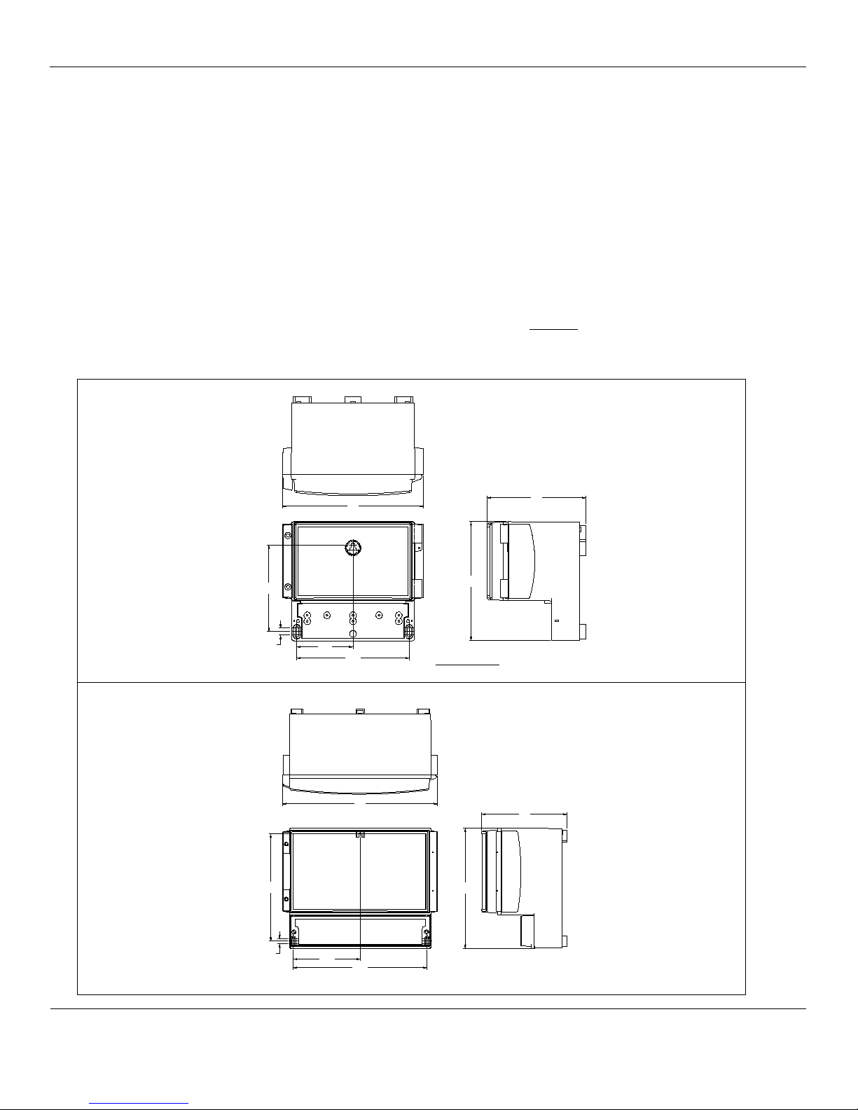
LC-4 Control Unit
Figure 2: Mounting LC Series
Page 7

LC-Series Controller: 1-4 Channel
ENMET
Manual Revi s i on Date – June 13, 2017
Page | 6
Manual Part No. – 80003-050
4.0 Wiring the LC Series
The electrical installation should conform to appropriate electrical codes, such as the National Electrical Code in the United States.
ARNING: The compliance o f the installation to appropriate codes is not ENMET’s responsibility.
W
4.1 System Wiring
All connections should be made according to the appropriate sensor or loop diagram for the configuration required. It is advised
that ‘Bootlace Ferrules’ or ‘flat blade crimps’ be used for tidy and reliable connections of wires into the Control Unit and Detector
Head connectors
Power Supply Input
An isolating switch should be provided between the power source and the MCU control units to allow the supply to be easily
disconnected. This should incorporate over current protection or a circuit breaker. Alternatively, a fused supply would suffice
AC Mains Connection
The power supply board has three screw terminals connector assigned for the connection of an AC supply.
Pin 1 = Ear th
Pin 2 = Live i nput
Pin 3 = Neutral input
Recommendation for mains input cable. 3-Core – 16 AWG Conductors having cross sectional area of 0.75mm
DC Voltage Connection
The power supply board has two screw terminals assigned for the connection of a DC supply
Pin 4 = +24V DC input
Pin 5 = 0V D C input
Cable Routing
Due to the low signal levels generated by gas detectors it is recommended that all wiring to the sensors by segregated away from
AC mains or other high voltage/power lines to avoid interference.
Cable Screening
The use of a screened cable is recommended for the installation of all detector heads. The screening is used to minimize the effects
of electrical interference generated by external equipment e.g. motors, switchgear etc. The correct strategy for connecting the
screens depends upon the area in which the detector head is to be used (i.e. hazardous/ non-hazardous). In all cases the screen
should not be connected at the detector head
2
minimum (24/0.2)
Page 8
LC-Series Controller: 1-4 Channel
ENMET
Manual Revi s i on Date – June 13, 2017
Page | 7
Manual Part No. – 80003-050
TRACO
®
POWER
FG
AC(N)
AC(L)
Input: 100 – 240 VAC
47-63 Hz
0.375 A max
Output: 24VDC / 625 mA
TML 15124
Fault relay
Fuse 1
Fuse 2
1 2 3 4 5 6 7 8 9 10 11 12
Common L3 Alarm
Relay
Power Switch
4.1.1 Power Supply Module
The Power Supply is sit uated on the LHS of the main PCB within the encl osure and provide s the power for the whole system.
The power supply is a standard item and does not require any modifications regardless of the type and quantity of detector
heads being used.
There are two power source options available to the system
100-240V AC Mains Supply, connectors 1, 2 and 3
18 to 28V DC Supply, connectors 4 and 5
There are two fuses situated on the main PCB. These are:
FS1 (T1.0A) AC s upply Fuse
FS2 (T500mA) DC Supply F us e
Page 9

LC-Series Controller: 1-4 Channel
ENMET
Manual Revi s i on Date – June 13, 2017
Page | 8
Manual Part No. – 80003-050
LC1
T R A C O
®
P O W E R
FG
AC(N)
AC(L)
Input: 100 – 240 VAC
47-63 Hz
0.375 A max
Output: 24VDC / 625 mA
TML 1512 4
Display PCB Connector
E
L
N
+24V
0V
15 16 17 18
- OUTPUT
+4-20 mA
+ SOUNDER
- SOUNDER
J1J2J3J4J5J6J7J8J9
J10
J11
J12
J13
J14
D5
D4
100 - 240
VAC D C
FLT
L1
L2
SENSOR
OPTIONS
COM
N.C
N.O
COM
N.C
N.O
COM
N.C
N.O
1 2 3 4 5 6 7 8 9 10 11 12 13 14 19 20 21 22
Channel 1
D5
D5
The LC Series Control Units are sin gle PCB design. Each Control Unit has a p ower supply section and 1, 2 or 4 I/O inter face
sections.
Located on the bottom edge of the main PCB is a number of screw connectors. This is used to provide connections for inputs,
outputs and external buttons:
4.1.3 Connections LC1
Pins 1, 2 and 3
AC power input
Pins 4 and 5
24VDC power input
Pins 6, 7 and 8
Common Fault relay contacts
Pins 9, 10 and 11
Common Alarm level1 relay co ntac ts
Pins 12, 13 and 14
Common Alarm level1 relay co ntac ts
Pins 15 to 18
I/O connection to sensors
Pins 19 to 20
4-20 mA output
NOTE: D5 orientation is be selected for 24Vdc supply as follows
Input Output
Page 10

LC-Series Controller: 1-4 Channel
ENMET
Manual Revi s i on Date – June 13, 2017
Page | 9
Manual Part No. – 80003-050
LC2
TRACO
®
POWER
FG
AC(N)
AC(L)
Input: 100 – 240 VAC
47-63 Hz
0.375 A max
Output: 24VDC / 625 mA
TML 15124
Display PCB Connector
E
L
N
+24V
0V
- OUTPUT
+4-20 mA
100 - 240
VAC D C
FLT
L3
SENSOR
OPTIONS
COM
N.C
N.O
COM
N.C
N.O
L1
COM
N.C
N.O
L2
COM
N.C
N.O
1413 15 16
1011121314
J1J2J3J4J5J6J7J8J9
FS1FS2
SW1
1
2 3
4
5
6 7 8 9 10 111213 14 151617
18
19 20
21
22 23 24
Note: connections 12 & 13 may not be fitted on some variants
Channel 1
4.1.4 Connections LC2
Pins 1, 2 and 3
AC power input
Pins 4 and 5
24VDC power input
Pins 6, 7 and 8
Common Fault relay contacts
Pins 9, 10 and 11
Common Alarm level 3 relay
contacts
Pins 13 to 16
I/O connection to sensors
Pins 17 to 18
4-20 mA output
Pins 19 to 21
Alarm Level 1 relay contacts
Pins 22 to 24
Alarm Level 2 relay contacts
Chanel 2
Pins 25 to 36
The same functions as 13 to 24
Power supply section I/O interface section Channel
Page 11

LC-Series Controller: 1-4 Channel
ENMET
Manual Revi s i on Date – June 13, 2017
Page | 10
Manual Part No. – 80003-050
LC4
TRACO
®
POWER
FG
AC(N)
AC(L)
Input: 100 – 240 VAC
47-63 Hz
0.375 A max
Output: 24VDC / 625 mA
TML 15124
Display PCB Connector
E
L
N
+24V
0V
- OUTPUT
+ 4-20 mA
100 - 240
VAC D C
FLT
L3
SENSOR
OPTIONS
COM
N.C
N.O
1413 15 16
1011121314
J1J2J3J4J5J6J7J8J9
FS1FS2
SW1
1 2 3 4 5 6 7 8 9 10 11 12
17 18
N.C
N.O
COM
L1
COM
N.C
N.O
18 19 20 21 22 23
L2
COM
N.C
N.O
14 15 1613
4.1.5 Connections LC4
Chanel 1
Connections
Sensor Options:
Pin 13: Signa l In (1 – 5 Vdc)
Pin 14: Signa l In (4-20mA)
Pin 15: Voltage Out to S/T
Pin 16: Ground to S/T
Chanel 2
Pins 25 to 36
The same functions as 13 to 24
Chanel 3
Pins 37 to 48
The same functions as 13 to 24
Chanel 4
Pins 49 to 60
The same functions as 13 to 24
An Earth ground is also provided
on the main PCB
The diagrams above show a pictorial representation of the various module positions within the LCU Series Control Units
The power s upply is situated on the LHS of the main PCB wit h the channel I/Os to the right of the PCB.
The microcontroller module and LCD display are mounted on the top of the front panel. This connects to the main PCB via a
single flat ribbon cable
NOTE: connections 12 & 13 may not be fitted on some variants.
Page 12

LC-Series Controller: 1-4 Channel
ENMET
Manual Revi s i on Date – June 13, 2017
Page | 11
Manual Part No. – 80003-050
CHANNEL 1
LEVEL
1
ALARM
LEVEL 2
ALARM
J1J2J3J4J5J6J7J8J9
+ve -Ve
4.2 Sensor Transmitter Installation
Mounting location for the gas detectors need to be considered individually, initial points for consideration are:
Ensure all gas detectors are mounted to allow routine calibration and maintenance to be carried out as required.
Ensure the proposed site will not interfere with movement of existing equipment, e.g. cranes, doo r s e tc
Install all cables neatly and securely.
Detectors for gases that are lighter than air should be positioned a t, or below, a high level.
Detectors for gases that are heavier than air should be located at below head height.
Avoid location the gas detectors adjacent to potential sources of radio frequency interference, e.g. radio transmitters,
control switchgear, motors etc.
Ensure the detectors are mounted with sufficient space to allow air movement around the sensor section.
4.2.1 Example 2 Wire Sensor Transmitter
4.2.2 Example 3 Wire Sensor Transmitter
Page 13

LC-Series Controller: 1-4 Channel
ENMET
Manual Revi s i on Date – June 13, 2017
Page | 12
Manual Part No. – 80003-050
5.0 Operation
When a preset alarm point is reached, visual and/or audio alarms are activated. The backlit graphics display automatically displays the
channel in alarm and an alarm level Led(s) are activated on the control panel. The LC-8 is factory set to maintain these alarms until
they are acknowledged.
5.1 LC-Series Microcontr oll er Module
Situated within the LC Control Unit front panel is the Microcontroller Module. This module communica te s with all Input channels
connected to the system PCB.
The Microcontroller Module provides a user interface in the form of a back lit graphics display and a four-button multifunction
keypad.
Three LED indications are provided directly by the Microcontroller Module and these are visible via MCU front panel:
Green LED for power.
Red LED indication of Alarm level 1.
Red LED indication of Alarm level 2
Red LED indication of alarm level 3.
Yellow LED indication of fault condition.
An Audible signal is also provided by a sounder mounted within Microcontroller module. This provides a local audible tone during
alarm or conditions.
The Microcontroller Module also provides the user with many configuratio n and interrogation facilities via the LCD and keypad.
These facilities include:
Sensor Configuration.
Allows adjustment of Sensor type and range (e.g. Flammable 100%LEL).
Calibration of the system.
This allows each channel to be calibrated independently. The sensor zero point and span can both be set via this function.
Calibration of the retransmitte d output for each channel.
Calibration of the channel power supply.
Input Module Relay Configuration.
Each Input Module contains two relays for alarm levels 1 and 2. The alarm levels can be individually set to be either rising
or falling.
Fault relay.
All relays can be configured normally energized or de-energized as required. Lat ching and non-latching functions ca n also
be selected.
The microcontroller module contains all of the software required to communicate with up to four detecting channels. The software
is common to all LC Series Control Units.
Page 14

LC-Series Controller: 1-4 Channel
ENMET
Manual Revi s i on Date – June 13, 2017
Page | 13
Manual Part No. – 80003-050
J1
J2
J3
J4
J5
J
6
J7
J8
J9
Detector Head Label
4-20mA Loop
Channel 1
Pin Number
Channel 2
Pin Number
Channel 3
Pin Number
Channel 4
Pin Number
–
14
26
38
50 + 15
27
39
51
Connection Procedure
Disconnect power from the system.
Remove the terminal cover to gain access to the wiring.
Remove the terminal cover and display module to gain access to the configuration link settings.
Configure the jumper switches as shown below (i.e. J1, J2, J4, J5, J8 and J9 switched ON, all others OFF)
Connect the wires fro m the detect or head to connector on the input module obse rving the following:
Connect power to the system and ensure the detector head operates (text on LCD display, LED will flash once every six
seconds approximately).
Perform software configuration (refer to ‘LC Software Configuration and System Calibration Manual’).
Perform system calibration (refer to ‘LC Software Configuratio n and System Calibration Manual’).
Page 15

LC-Series Controller: 1-4 Channel
ENMET
Manual Revi s i on Date – June 13, 2017
Page | 14
Manual Part No. – 80003-050
Chart recorder
0V
Alarm
level 1
J1J2J3J4J5J6J7J8J9
J10
J11
J12
J13
J14
Alarm
level 2
14
15
16 17 18 19 20 21 22 23 24
Channel 1
26
27
28 29 30 31 32 33 34 35 36
Channel 2
38
39
40 41 42 43 44 45 46 47 48
Channel 3
50
51
52 53 54 55 56 57 58 59 60
Channel 4
16
17
18
LC 1
15
13
25
37
49
J10
J11
J12
J13
J14
5.2 Analogue Output Configuration
In addition to providing the connections for various connector types, the Input Module can also provide an analogue output. This
output mimics the signal detected so that it may be used by external equipment (e.g. chart recorders, data loggers) for a variety of
purposes.
NOTE: It is important to ensure that the Analogue Output is calibrated if in use (refer to ‘MCU Software Configuration and
System Calibration Manual’).
5.2.1 4-20mA Current Source
The Input Module sourc es current proportional to the detected gas level.
i.e. zero gas = 4mA
full scale = 20mA
The supply is taken from the internal PSU. Switch ON J12 and J14
NOTE: Incorrect jumper switch configuration can cause damage to the system.
Page 16

LC-Series Controller: 1-4 Channel
ENMET
Manual Revi s i on Date – June 13, 2017
Page | 15
Manual Part No. – 80003-050
Chart recorder
+
24VDC
0V
Alarm
level 1
J
10
J11
J
1
2
J1
3
J
1
4
Alarm
Level 2
14 15 16 17 18 19 20
21 22 23 24
Channel 1
26
27
28 29 30 31 32 33 34
35 36Channel 2
38
39
40
41 42 43 44 45
46 47 48
Channel
3
50 51 52 53 54 55 56 57 58
59 60Channel
4
16 17 18LC
1 15
13
25
37
49
19 20
J10
J11
J12
J13
J14
5.2.2 4-20mA Current Sink
The Input Module can also sink current proportional to the detected gas level.
i.e. zero gas = 4mA
full scale = 20mA
The supply is derived from the external equipment.
NOTES
Switch ON J10 and J13
NOTE: Incorrect jumper switch configuration can cause damage to the system.
Page 17

LC-Series Controller: 1-4 Channel
ENMET
Manual Revi s i on Date – June 13, 2017
Page | 16
Manual Part No. – 80003-050
Alarm
level 1
J1
0
J11
J
1
2
J
13
J1
4
Alarm
Level 2
14 15 16
17 18 19
20 21 22
23 24Channel 1
26
27
28 29
30
31 32
33 34
35 36
Channel 2
38
39
40
41 42 43 44
45 46 47 48
Channel
3
50 51
52
53
54
55 56
57
58 59
60Channel
4
16 17 18
LC 1
15
13
25
37
49
19 20
Chart recorder
+ve
-
ve
J10
J11
J12
J13
J14
5.2.3 1-5V Voltage Output
The LC Control Unit can provide a volta ge o utp ut.
i.e. zero gas = 1V
full scale = 5V
This output is not ideal when transmitting a signal over a large distance. The resistance of a cable attached will cause a voltage
drop to occur.
Switch ON J11, J12 and J14.
NOTE: Incorrect jumper switch configuration can cause damage to the system.
Page 18

LC-Series Controller: 1-4 Channel
ENMET
Manual Revi s i on Date – June 13, 2017
Page | 17
Manual Part No. – 80003-050
6.0 Maintenance
Routine Servicing
The MCU Control Unit will provide a reliable and fault free service but they rely upon sensible housekeeping and regular calibrations.
It is recommended that the system be calibrated at least once every six months. This can be arranged with Status Scient ific Contr ols
as part of a maintenance contract.
Routine Inspection
It is advisable to periodically inspect the LC Control Unit Installation:
Check cables to ensure no damage has occurred.
Clean control unit casing using a clean cloth.
Clean detector heads using a clean DAMP cloth.
NOTE: Use of a dry cloth would constitute a static hazard.
Inspect detector heads and ensure the sensor housings aperture is not obstructed.
NOTE: Do not use solvents to clean the LCD display window on the control units or the detector heads
The time interval between routine inspections will depend upon the area in which the equipment is installed. A clean laboratory
installation may only require inspectio n at the time of calibration, whereas an installation in a particularly dirty environment may
require weekly inspections. It is the re sponsibility of the syste m engineer to assess the installation environment and determine the
frequency o f routine i ns pections
Page 19

LC-Series Controller: 1-4 Channel
ENMET
Manual Revi s i on Date – June 13, 2017
Page | 18
Manual Part No. – 80003-050
Type
LC1
Size (nominal) ‘mm’
188 x 160 x 106
Weight (approx.)
Operating Temp
-10ºC to +50ºC
Storage Temp
-20ºC to +50ºC
Humidity Range
0 to 95% R.H. Non-condensing
Input Voltage
18-28V DC, or 100-240V AC 50/60 Hz
Environme ntal Rat i ng
IP65
User Interface
Display
Backlit 122 x 32 dot Liquid Crystal Display (LCD)
Keyboard
4 button multif unc ti o n ke ypad
Red
Green
Indicates alarm condition.
Indicates power ON
Red
Yellow
Indicates alarm level 1 conditio n.
Indicates fault condition.
Input Modules
Number of channels
1 max
4-20mA Current Loop from 24V source.
3-Wire Pellistor Systems.
4-20mA Current source prop ortional to detected signal.
1-5V Voltage output proportional to detected signal.
3 – Relays
Rating
1 relay assigned to alarm level 1.
5A 240V AC.
Power Supply
Fuse 1 (AC I nput)
T1.0A
Fuse 2 (24V DC input)
T500mA
7.0 Technical Data and Specifications
LC1
LED Indications
Option 1
LED Indications
Option 2
Signal Inp ut
Analogue Output
Contacts
Yellow
Red
Indicates fault condition.
Indicates alarm level 2 conditio n.
4-20mA Current Loop sink to 0V.
4-20mA Current sink proportional to detected signal.
1 relay assigned to alarm level 2.
1 relay assigned to fault condition.
Single Pole Changeover Contacts (voltage free).
OTE: All specifications stated in this manual may change without notice.
N
Page 20

LC-Series Controller: 1-4 Channel
ENMET
Manual Revi s i on Date – June 13, 2017
Page | 19
Manual Part No. – 80003-050
Type
LC2
Size (nominal) ‘mm’
280 x 219 x 156
Weight (approx.)
1.9Kg
Operating Temp
-10ºC to +50ºC
Storage Temp
-20ºC to +50ºC
Humidity Range
0 to 95% R.H. Non-condensing
Input Voltage
18-28V DC, or 100-240V AC 50/60
Environme ntal Rat i ng
IP65
User Interface
Display
Backlit 122 x 32 dot Liquid Crystal Display (LCD)
Keyboard
4 button multif unc ti o n ke ypad
Red
Green
Indicates alarm condition.
Indicates power ON
Green
Yellow
Indicates power ON
Indicates fault condition.
Input Modules
Number of channels
2 max
4-20mA Current Loop from 24V source.
3-Wire Pellistor Systems.
4-20mA Current source proportional to detected signal.
1-5V Voltage output proportional to detected signal.
1 relay assigned to alarm level 1, channel 1 & 2.
5A 240V AC.
Power Supply
Fuse 1 (AC I nput)
T1.0A
Fuse 2 (24V DC input)
T500mA
LC2
LED Indications
Option 1
LED Indications
Option 2
Signal Inp uts x 2
Analogue O utp ut x 2
6 – Relays
Contacts
Rating
Yellow
Red
Red
Red
Indicates fault condition.
Indicates alarm level 3 conditio n.
Indicates alarm level 2 conditio n.
Indicates alarm level 1 condition.
4-20mA Current Loop sink to 0V.
4-20mA Current sink proportional to detected signal.
1 relay assigned to alarm level 2, channel 1 & 2.
1 relay assigned to common alarm level 3.
1 relay assigned to fault condition.
Single Pole Changeover Contacts (voltage free).
N
OTE: All specifications stated in this manual may change without notice.
Page 21

LC-Series Controller: 1-4 Channel
ENMET
Manual Revi s i on Date – June 13, 2017
Page | 20
Manual Part No. – 80003-050
Type
LC4
Size (nominal) ‘mm’
390 x 316 x 167
Weight (approx.)
3.8Kg
Operating Temp
-10ºC to +50ºC
Storage Temp
-20ºC to +50ºC
Humidity Range
0 to 95% R.H. Non-condensing
Input Voltage
18-28V DC, or 100-240V AC 50/60 Hz
Environme ntal Rat i ng
IP65
User Interface
Display Option 1
LED Backlit 122 x 32 dot Liquid Crystal Display (LCD)
Display Option 2
LED Backlit 240 x 128 dot Liquid Crystal Display (LCD)
Keyboard
4 button multif unc ti o n ke ypad
Red
Green
Indicates alarm condition.
Indicates power ON
Green
Yellow
Indicates power ON
Indicates fault condition.
Input Modules
Number of channels
4 max
4-20mA Current Loop from 24V source.
3-Wire Pellistor Systems.
4-20mA Current source proportional to detected signal.
1-5V Voltage output proportional to detected signal.
1 relay assigned to alarm level 1, channel 1, 2, 3 & 4.
5A 240V AC.
Power Supply
Fuse 1 (AC I nput)
T1.0A
Fuse 2 (24V DC input)
T500mA
LC4
LED Indications
Option 1
LED Indications
Option 2
Signal Inp uts x 4
Analogue Output x 4
10 – Relays
Contacts
Rating
Yellow
Red
Red
Red
Indicates fault condition.
Indicates alarm level 3 conditio n.
Indicates alarm level 2 conditio n.
Indicates alarm level 1 conditio n.
4-20mA Current Loop sink to 0V.
4-20mA Current sink proportional to detected signal.
1 relay assigned to alarm level 2, channel 1, 2, 3 & 4.
1 relay assigned to common alarm level 3.
1 relay assigned to fault condition.
Single Pole Changeover Contacts (voltage free).
OTE: All specifications stated in this manual may change without notice.
N
Page 22

LC-Series Controller: 1-4 Channel
ENMET
Manual Revi s i on Date – June 13, 2017
Page | 21
Manual Part No. – 80003-050
Phone: 734-761-1270
Fax: 734-761-3220
8.0 Terms and Conditions
8.1 Ordering Information
Address orders to:
ENMET
Attention: Customer Service Dep a rtment
680 Fairfield Court
Ann Arbor, MI 48108
Email Orders: orderentry@enmet.com
You may also contact our customer service department by email info@enmet.com. MINIMUM ORDER IS $50.00.
8.2 Delivery
Unless Seller otherwise specifies, delivery will be made: FOB Ann Arbor, MI and/or FOB Bowling Green, KY. Title and risk of
loss shall pass to Buyer at that po int. Shipping and handling charges will be Prepaid and Added to Buyer’s invoice. Buyer may
request shipping be charged to their own account with a preferred carrier. Seller shall have the right to choose means of
transportation and to route shipment when specific instructions are not included with Buyer’s order. Seller agrees to deliver the
goods and services, within the time, in accordance with specifications, at the prices specified on the face hereof. Buyer’s orders to
this quotation are not subject to c a ncella tion or deferment of delivery without indemnification of loss to the Seller resulting there
from. Seller shall not be liable to Buyer for any loss or damage sustained on account of this delay or nonperformance due to
causes beyond Seller’s control and without his fault or ne gligence. W here performance of t he terms here is contingent upon timely
delivery of goods or services by the Buyer and such delivery is in default, Seller shall be indemnified for any damage or loss
resulting there fro m, a nd/or by extension of Seller’s delivery commitment, as applicable.
8.3 Payment Terms
Payment Terms are Net 30 Days from the date of shipment from Seller unless otherwise noted. All shipping and handling costs
will be charged to Buyer on a Prepaid and Add basis. Buyer has the option of paying for shipping by charging its own account
with a carrier
8.4 Warranty Information and Guidelines
The Seller warrants new instruments to be free from defects in workmanship and material under normal use for a period of one
year from date of shipment. The warrant covers both parts and labor excluding calibration and expendable parts such as filters,
detector tubes, batteries, etc. If the inspection by the Seller confirms that the product is defective, it will be repaired or replaced at
no charge, within the stated limitations, and returned prepaid to any location in the United States. The Seller shall not be liable for
any loss or damage caused by the improper use or installation of the product. The Buyer indemnifies and saves harmless the Seller
with respect to any loss or damages that may arise through the use by the Buyer or ot hers of this equipment. This warranty is
expressly given in lieu of all other warranties, either expressed, implied or statutory, including that of mer c hantability, and all
other obligations, or liabilities of ENMET, LLC for damages arisin g out of or in connectio n with the use or repair or performance
of the product. In no event shall ENMET, LLC, be liable for any indirect, incidental, special or consequential damages or for any
delay in the performance by ENMET, LLC, which may arise in connection with this equipment. ENMET neither assumes nor
authorizes any representatives or other persons to assume for it any obligation or liability other than that which is set forth here in.
Buyer agrees to indemnify and save harmless Seller for any damage or loss from lawsuits against Seller by reason of manufacture
of sale of materials, parts, or use of processes resulting from Buyer’s design specifications. Any patent, design, pattern, tool, die,
jig, fixture, drawing, test equipment, or process furnished by Seller; whether possessed by the Seller before the date of this
quotation, or devised or acquired by Seller during performance of the terms of this quotation, shall remain the property of the
Seller except by specific stipulation on the face hereof. Seller reserves the right, without liability, for damage or loss, to destroy
Buyer’s drawings, specifications, patterns and special tools supplied by Buyer for performance of the terms on the face hereof,
unless Buyer gives noti ce of the disposition of such items.
8.5 Return Policy
All returns for credit must be approved in advance by ENMET, LLC. Such returns are subject to a minimum $50.00 or 20%
restocking charge, whichever is greater. Approval of equipment for return is totally at the discretion of ENMET, LLC. All
requests for return/exchange must be made no later 30 days of the original shipping date from ENMET. The actual amount of any
resulting credit will not be determined prior to a complete inspection of the equipment by ENMET. Calibration gas cylinders
cannot be returned or restocked.
Page 23

LC-Series Controller: 1-4 Channel
ENMET
Manual Revi s i on Date – June 13, 2017
Page | 22
Manual Part No. – 80003-050
9.0 Instructions for Returning an Instrument for Service
Contact the ENMET Service Department for all service requests.
Phone: 734-761-1270
Email: repair@enmet.com
Fill out the “Service Request Fo rm” found at t he end of thi s manual and return with your instrument fo r all needs. Please send your
instrument for service to the site in which the product was purchased. A new “Service Request Form” may be requested if the one
found in the manual is not available. All instruments should be shipped prepaid to ENMET.
Address for Service:
Michigan Location:
Kentucky Loc ati o n:
Providing the “Service Request Form” assists in the expedient service and return of your unit and failure
to provide this information can re su lt in p rocessing delays. ENMET charges a one hour minimum billing for all a pproved repairs with
additional time billed to the closest tenth of an hour. All instruments sent to ENMET are subject to a minimum evaluation fee, even if
returned unrepaired. Unclaimed instruments that ENMET has received without appropriate paperwork or attempts to advise repair
costs that have been unanswered after a period of 60 days may, be disposed of or returned unrepaired COD and the customer will be
expected to pay the evaluation fee. Serviced instruments are returned by UPS/FedEx Ground and are not insured unless otherwise
specified. If expedited shipping methods or insurance is required, it must be stated in your paperwork.
NOTE: Warranty of customer installed components.
For Warranty Repairs, please reference ENMET’s “Warranty Information and Guidelines” (found earlier in this section).
ENMET
Attention: Service Department
680 Fairfield Court
Ann Arbor, MI 48108
ENMET
62 Corporate Court
Bowling Green, KY 42103
Page 24

Mailing/Shipping Address:
ENMET
repair@enmet.com
Fax: 734.761.3220
Rev.2 – 9/15/2016
Service Request Form
PAYMENT METHOD
☐ COD
☐ VISA/MasterCard
☐ American Express
Card Number
Exp. Date Security Code:
Name as it Appears on
Card:
RETURN SHIPPING METHOD
☐
☐
Select
☐
Air
☐
Saver
☐
UPS Account #:
☐
☐
Express Saver
☐
Overnight Std.
☐
Day
☐
Overnight P-1
FedEx Account #:
Insure Shipment:
☐
☐
Insurance
Amount:
$
Product Name or Number:
Product Serial Number:
Describe Problem or Needed Service:
Warranty Claim?
☐
☐
CUSTOMER INFORMATION
Billing Address:
Shipping Address:
Contact Name:
Phone #:
Email:
Fax #:
PO/Reference
#:
680 Fairfield Court
Ann Arbor, MI 48108
Service Request Form
Phone: 734.761.1270
Yes
No
UPS Ground
FedEx Ground
UPS 3 Day
FedEx Air
Yes
ENMET
No
UPS Next Day
FedEx Air
UPS ND Air
FedEx Air 2
UPS 2 Day Air
FedEx Air
 Loading...