

Page 1

ENMETENMET Corporation
PO Box 979
Ann Arbor, MI 48106-0979
ISA – MISA – M
OPERATION & M AINTENANCE
MANUAL
80003-027
04/27/95
MCN-204, 10/20/98
MCN-285, 11/20/02
Page 2

Table of Contents
1.0 INTRODUCTION................................................................................................................................1
1.1 Unpack ................................................................................................................................................................................1
1.2 Check Order.......................................................................................................................................................................1
1.3 Serial Numbers .................................................................................................................................................................. 1
1.4 Read Manual ...................................................................................................................................................................... 1
2.0 F EATURES IF THE ISA – M................................................................................................................2
2.1 External Feature of the ISA – M.....................................................................................................................................2
2.2 Internal Features of the ISA – M .................................................................................................................................... 3
4.0 INSTALLATION ................................................................................................................................4
4.1 Mounting and Power Hook-up........................................................................................................................................4
4.2 Sensor Location ................................................................................................................................................................. 5
4.3 Sensor Hook-up.................................................................................................................................................................6
4.4 Sensor Heater Voltage......................................................................................................................................................7
5.0 OPERATION....................................................................................................................................8
5.1 Warm – Up ......................................................................................................................................................................... 8
5.2 Precautions.........................................................................................................................................................................8
5.3 Rough Test.........................................................................................................................................................................8
6.0 ROUTINE GAS TEST AND RECALIBRATION...........................................................................................9
6.1 Test......................................................................................................................................................................................9
6.2 To Recalibrate .................................................................................................................................................................. 10
7.0 MAINTENANCE.............................................................................................................................. 11
4.1 Basic Troubleshooting...................................................................................................................................................11
7.2 Sensor Replacement........................................................................................................................................................11
7.3 Replacement Part Numbers...........................................................................................................................................12
8.0 SPECIFICATIONS ........................................................................................................................... 12
8.1 Options and Variations...................................................................................................................................................12
9.0 WARRANTY............................................................................................................................... 13
9.1 Repair of Certain Units .................................................................................................................................................. 13
List of Figures and Tables
FIGURE 1: EXTERNAL FEATURES OF THE ISA – M.....................................................................................2
FIGURE 2: INTERNAL FEATURES OF THE ISA – M......................................................................................3
FIGURE 3: MOUNTING DIMENSIONS OF THE ISA – M..................................................................................4
TABLE 1: HEAVIER THAN AIR..................................................................................................................5
TABLE 2: LIGHTER THAN AIR..................................................................................................................5
TABLE 3: SAME DENSITY AS AIR.............................................................................................................5
FIGURE 4: INTERNAL VIEW OF S ENSOR WIRING.........................................................................................6
TABLE 4: RECOMMENDED WIRE GAUGE...................................................................................................6
FIGURE 5: EXPOSING A S ENSOR TO TEST OR CALIBRATION GAS .................................................................9
TABLE 5: APPROXIMATE ALARM TIME...................................................................................................10
Reference information:
NOTE: [important information about use of instrument – if not followed may have to redo some steps.]
CAUTION: [affects equipment – if not followed may cause damage to instrument, sensor etc…]
WARNING: [affects personnel safety – if not followed may cause bodily injury or death.]
Page 3

ISA – M ENMET Corporation
1.0 Introduction1.0 Introduction
The ENMET Model ISA-M detector/alarm is an all solid-state electronic gas-detecting instrument that minimizes the
risk of harm or death to people who are exposed to potentially hazardous gas environments. It continuously monitors
for combustible or toxic gases and warns of a dangerous gas situation with enough time to take action to avoid harm.
Audio (horn) and visual (light) alarms are calibrated to trigger at both high and low level gas concentrations.
The ISA-M uses a gas-sensitive Metallic Oxide Semiconductor (MOS) sensing element which reacts to toxic and
combustible gas molecules. An oxidation reaction occurs on the sensor surface when contaminants are present. The
oxidation reaction changes the sensor's electrical resistance which then triggers the alarm circuitry when the
concentration of gas goes beyond a preset level.
The sensor can be located up to 1000 feet from the circuit enclosure and connected electrically by wire or cable.
NOTE: All specifications stated in this manual may change without notice.
1.1 Unpack
Unpack the ISA – M and examine it for shipping damage. If such damage is observed, notify both ENMET customer
service personnel and the commercial carrier involved immediately.
Regarding Damaged Shipments
NOTE: It is your responsibility to follow these instructions. If they are not followed, the carrier will
not honor any claims for damage.
q This shipment was carefully inspected, verified and properly packaged at our company and delivered to the
carrier in good condition.
q When it was picked up by the carrier at ENMET, it legally became your company’s property.
q If your shipment arrives damaged:
• Keep the items, packing material, and carton “As Is.” Within 5 days of receipt, notify the carrier’s local office
and request immediate inspection of the carton and the contents.
• After the inspection and after you have received written acknowledgment of the damage from the carrier,
contact ENMET Customer Service for return authorization and further instructions. Have your Purchase Order
and Sales Order numbers available.
q ENMET either repairs or replaces damaged equipment and invoices the carrier to the extent of the liability
coverage, usually $100.00. Repair or replacement charges above that value are your company’s responsibility.
q The shipping company may offer optional insurance coverage. ENMET only insures shipments with the
shipping company when asked to do so in writing by our customer. If you need your shipments insured, please
forward a written request to ENMET Customer Service.
Regarding Shortages
If there are any shortages or questions regarding this shipment, please notify ENMET Customer Service within 5 days
of receipt at the following address:
ENMET Corporation
680 Fairfield Court
Ann Arbor, MI 48108
734-761-1270 734-761-3220 Fax
1.2 Check Order
Check, the contents of the shipment against the purchase order. Verify that the ISA – M is received as ordered. Each
ISA – M is labeled with its target gas. If there are accessories on the order, ascertain that they are present. Check the
contents of calibration kits. Notify ENMET customer service personnel of any discrepancy immediately.
1.3 Serial Numbers
Each ISA – M is serialized. These numbers are on tags on the equipment and are on record in an ENMET database.
1.4 Read Manual
Read this manual carefully and thoroughly before installing and operating this instrument.
1
Page 4
ENMET Corporation ISA – M
Switch Indicator
Audio Alarm
Visual Alarm
Power Indicator
Visual Alarm
2.0 Features if the 2.0 Features if the ISA – M
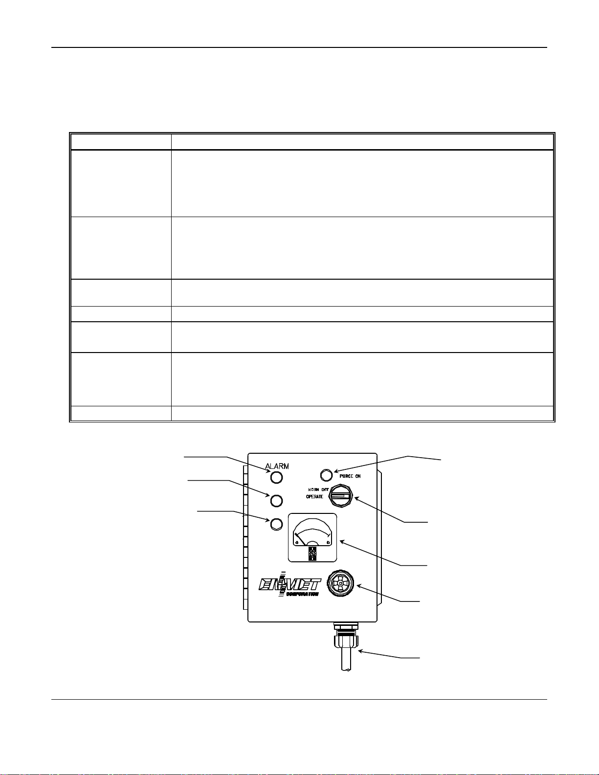
2.1 External Feature of the ISA – M
Figure 1 shows the ISA-M control unit which contains the electronic circuitry and controls. Main features are listed below.
Feature Description
Meter
Operation Switch A rotary switch for:
Switch Indicator
(Red)
Audio Alarm(Horn) Audio alarm (2900 Hz, 95 dB at 2 ft.). The audio alarm is activated when the unit is in alarm.
Power Indicator
(Green)
Visual Alarms Amber: Visual alarm (steady light). When this lamp is on, power to the unit is on and the unit
This is a non-linear device. Do not infer exact readings from unmarked regions of the meter
scale.
The scale is marked in units of measure for the gas depending on instrument calibration.
§ PPM (Parts Per Million) for toxic gases
§ % LEL (Lowest Explosive Level) for combustible gases
§ OPERATE – Normal Operation
§ HORN OFF – Disable Audio Alarm
§ PURGE ON – (sensor temperature control) Purge ON to clean (purge) sensor surface of
absorbed contaminants (sensor hot).
When the light is on, Indicates OPERATION SWITCH is not in OPERATE
When the light is on, the unit is operating and is not in alarm.
When this light is off, the unit is in alarm OR power to the unit has been interrupted.
is in low alarm.
Red: Visual alarm (steady light). When this lamp is on, power to the unit is on and the unit is
in high alarm.
(Green)
(Red)
(Amber)
(Red)
Operation Switch
Meter
(Horn)
Power Cord
Figure 1: External Features of the ISA – M
2
Page 5
ISA – M ENMET Corporation
Suggested wiring configuration for Utilizing Relay Contacts
Common
Normally
Manual On/Off
110 Vac
12 V
Internal Relay
Contacts
Purge Adjust
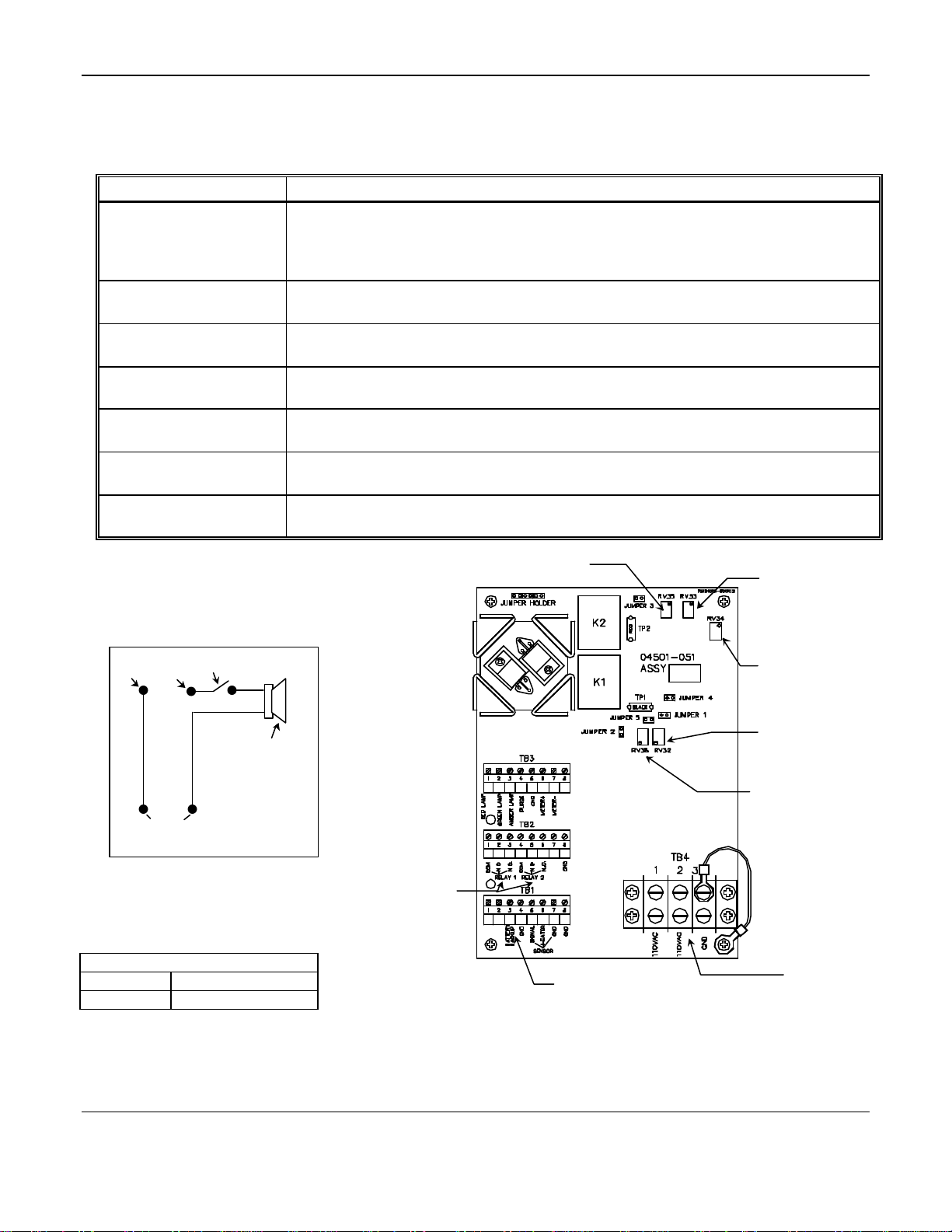
2.2 Internal Features of the ISA – M
Figure 2 shows the circuit board and terminal blocks housed inside the hinged oiltight control unit. Specific relays and
adjustments are defined in the table below.
Feature Description
Internal Relay Contacts
Potentiometers(POT) The unit has five potentiometers. These vary circuit resistances and are essential to
Heater Adjust
(RV32)
Low Level Alarm
(RV35)
High Level Alarm
(RV34)
Meter Adjust
(RV33)
Purge Adjust
(RV38)
There is one relay for each alarm level. Relays can be used to activate an external remote
alarm signal when a hazardous gas level is detected, or when the ac or dc power is
interrupted. These are double-pole relays with terminals "normally open", "normally
closed" and "common" (see figure 3 for relay contact hook-up).
calibration procedures. These potentiometers are described below.
For adjusting the sensor heater voltage (see section 4.4)
For low-level alarm adjustment (calibration, see section 6.2).
For high-level alarm adjustment (calibration, see section 6.2).
To adjust and set the meter for appropriate gas response during calibration. (See section 6.2)
For adjusting the sensor heater voltage on units that require periodic purging (cleaning) of
the sensor. (See section 4.4)
(manual on/off switch is suggested; user supplied component)
Closed
Contact
Contact
Black
Power supply Outside
of Control Unit
Switch
Horn
White
Non-Latching Relay contacts:
Identified below is the non-powered
(power to unit is off), alarm positions of
the non-latching relay contacts.
Terminal Block 2 see Figure 5
Relay 1 High Alarm
Relay 2 Low Alarm
NOTE: N.C.= normally closed
N.O.= normally open
Low-level Alarm
(POT RV35)
Input
DC
Meter Adjust
(POT RV33)
High-level Alarm
(POT RV34)
Heater Adjust
(POT RV32)
(POT RV38)
110/115
or
220/230*
*See section 4.2
Figure 2: Internal Features of the ISA – M
3
Page 6

ENMET Corporation ISA – M
4.0 Installation4.0 Installation
The ISA – M is completely oiltight. Use the correct oiltight fitting for the cord or conduit when supplying power to
the unit.
NOTE: This instrument is NOT rated for hazardous locations. The instrument must be located in a NON-Hazardous area.
4.1 Mounting and Power Hook-up
Figure 3: Mounting Dimensions of the ISA – M
1. A 110 VAC line cord is supplied, plug this into an appropriate outlet.
2. If conduit is preferred, remove the terminal strip cover from TB4 inside the control unit (simply pull the cover off
of its holding prongs). Apply 110 VAC power to the appropriate terminals. (Refer to Figure 2).
CAUTION: Utilizing 220 VAC power requires a change in the transformer hook-up by a competent electrician or
electronics technician; but this change is best done at ENMET.
12 VDC may be used as a primary source (refer to Figure 2) or as an emergency back-up source, both ac and dc
power can be applied at the same time. Current flows from the ac source; dc current will flow only when the ac
power is interrupted.
3. Run the relay contact leads through the same oiltight fitting as the power supply leads or out through a second
fitting.
NOTE: When the power supply is interrupted, the relays switch to the same position as for a true gas alarm condition,
and the power light goes off. Do not connect the unit to other voltage supply lines.
4. Replace terminal strip cover on TB4 inside the control unit.
5. Proceed to Section 5.0 for initial warm-up and operating procedures.
4
Page 7

ISA – M ENMET Corporation
4.2 Sensor Location
Gases have different densities. Some are heavier than air and concentrate at the bottom of a space. Some are lighter
than air and gather at the top. Consider the density of the gas you want the sensor to detect when you install the
sensor. Some examples are given below.
Table 1: Heavier than Air
Gas Sensor Location
Bottled LP (liquefied petroleum)
Propane
Butane
Gasoline
Trichloroethylene
Vaporized hydrocarbons
Hydrogen sulfide
Interior wall; 18-24" from floor.
§ DO NOT locate directly above or beside gas
appliances (ovens, heaters).
§ Avoid locating anywhere near a vent or window or
near an outside doorway.
Table 2: Lighter than Air
Gas Sensor Location
Natural gas (methane)
Ammonia
Hydrogen
Near ceiling.
§ DO NOT locate directly above appliances where it is
subject to direct exposure to heat or steam.
Table 3: Same Density as Air
Gas Sensor Location
Carbon Monoxide 4-6 feet above the (generally uniform) floor.
§ DO NOT locate in direct air currents of windows, doors, or vents.
If you have a question involving the location of a unit or sensor, please contact your distributor or ENMET personnel.
A technician will analyze the question and recommend a location.
5
Page 8

ENMET Corporation ISA – M
Optional
Sensor Wiring
4.3 Sensor Hook-up
The MOS sensor is connected to the ISA-M control unit with three conductor wiring, use the correct oiltight fitting.
Two conductors supply heater current to the sensor. The third conductor is a signal wire. Size of heater wire depends
on the distance between the particular sensor and the control unit. See Table 4.
Sensor wires correspond to the normal wire code:
orange – heater
brown – heater ground
blue – signal
Splash Shield
Sensor Wiring
FOR 812 / 813 / 814 SENSORS
Position Function Wire Color
1 Signal (Blue)
2 Heater (Orange)
3 Ground (Brown)
Terminal
Figure 4: Internal View of Sensor Wiring
NOTE: The three color-coded wiring attachments must be performed by the user when replacing the sensor.
Table 4: Recommended Wire Gauge
Distance from Sensor to Control Unit Recommended Wire Gauge
250 feet 16 AWG
350 feet 14 AWG
Longer Distances Contact Factory
CAUTION: After you mount and install the ISA – M, you must adjust the sensor heater voltage (see section 4.4).
6
Page 9

ISA – M ENMET Corporation
4.4 Sensor Heater Voltage
Heating the sensor promotes the oxidation reaction on the element surface. The temperature to which the sensor
element is heated determines the selectivity of the equipment to certain gases.
A chart, located inside the instrument front cover, specifies the voltage for the sensor. Units requiring purging have
two voltages specified. Refer to Figure 2 for potentiometer locations.
NOTE: Do not increase any sensor voltage to values greater than those given on the chart. Too high voltage can
damage the sensor heater winding; and if that happens you have to replace the sensor.
YOU NEED:
§ A digital voltmeter with a + or - 0.05% accuracy
§ A small screwdriver for adjusting pots.
Measure DC volts across the brown and orange wires in the sensor assembly at the sensor, not at the terminal strip.
EXCEPTION: If your sensor is mounted directly onto the side of the enclosure, then measure DC volts at the terminal
strip -- TB1-7 (ground) and TB1-6 (heater).
SENSORS REQUIRING PURGING :
1. Turn the switch to PURGE ON and adjust RV38 (purge POT.) to the voltage specified on the chart inside the unit
(see Figure 2). NOTE: Adjust this pot. clockwise to increase, counterclockwise to decrease the voltage.
2. Switch to HORN OFF.
3. Now adjust the sensor heater pot. RV32 to the required voltage.
NOTE: Adjust this pot. clockwise to increase, counterclockwise to decrease the voltage.
SENSORS NOT REQUIRING PURGING:
Adjust the sensor heater pot. (RV32 ; see Figure 2) to the required voltage.
NOTE: Sometimes, if a sensor is located a great distance from the control unit, the heater adjust may not, by itself,
be able to bring the voltage to the required reading. If not, then adjust the purge adjust pot., RV38, to arrive
at the necessary voltage.
NOTE: Once you have set the voltage at the sensor, check and record the voltage across TB1-7 (ground) and TB1-6
(heater). The next time you must check the sensor heater voltage, first check the voltage across TB1-7 and
TB1-6. If this voltage has not changed, the sensor heater voltage at the sensor has also not changed. If the
voltage across TB1-7 and TB1-6 has changed, you must reset the voltage at the sensor as described in the
procedures above.
7
Page 10

ENMET Corporation ISA – M
5.0 Operation5.0 Operation
Mount and install the ISA – M electronics unit and sensor as outlined in the previous section (4.0).
NOTE: There is no ON/OFF switch on the unit. As a safety device, this unit is designed to be powered and ON at all
times.
5.1 Warm – Up
1. Turn the switch to PURGE ON (when applicable) or HORN OFF.
2. For 5-30 minutes, after first applying power, the red gas alarm light stays on as the sensor heats and purges
(clears) its surface of contaminating molecules that have collected while the sensor was inactive.
3. When the red and amber light turns off, and the green power light comes on, the initial warm-up is complete.
4. Turn the switch to OPERATE.
Reference: State of Operation of the ISA – M
Normal Operation:
Green power light is on. Green power light is off.
No alarms. Red or Amber light is on.
Switch is in the operate position. Audio alarm on.
Enclosure feels warm to the touch.
Alarm State:
Relay contacts in alarm position.
WARNING: Any spontaneous alarm not triggered by the initial warm-up or rough test ( see section 5.3) should be
considered a potentially serious gas alarm situation. TAKE ACTION!
è Vacate all persons from the affected area. Observe these people for signs of toxic gas poisoning, carbon
monoxide poisoning, etc.
è Open windows or vents where it is feasible; then, after the contaminated area is cleared, turn off all gas and
electric appliances and gas pilot lights.
è Check all gas appliances and fixtures for leaking gas, pilot light failures, defective valves, and improper
ventilation.
è Follow your company's prescribed safety procedures in addition to those mentioned above.
5.2 Precautions
Do not blow cigarette smoke on a sensor.
Do not squirt pure gases or liquid hydrocarbons, such as butane, propane, gasoline, etc. directly on the sensor.
Do not use a strong cleaning agent, wax or lacquer near a sensor.
5.3 Rough Test
To see that the instrument is capable of alarming:
1. Hold a butane lighter near the sensor cover.
2. Briefly depress the lever, without striking the flint, to squirt some butane vapors.
3. The alarm should trigger; green power light goes off and the red light and horn activate.
CAUTION: This rough test method is best for units that are set primarily for hydrocarbon responses (combustible). Many
units set to respond to toxic gases or vapors require calibration gas to verify the alarm response capability.
8
Page 11

ISA – M ENMET Corporation
Sensor
Sensor
To Cal Cup
6.0 Routine Gas Test and Recalibration6.0 Routine Gas Test and Recalibration
Perform this test at regular intervals, you decide how often; we recommend that you do it at least every six weeks.
NOTE: The gases should be identical, or equivalent (correlation gas) to those used to initially calibrate the unit, unless
you want to recalibrate to a new gas or different concentration. In addition, calibration gases must be in a
background of air; do not use gases with an inert gas background (such as nitrogen or argon).
6.1 Test
YOU NEED:
§ Cylinder of high-level calibration gas with air used as background gas (for example 200 ppm CO in air)
§ Calibration fixture (with humidifier/regulator, plastic tubing and calibration cup); ENMET part # 03700-001
§ Clean water
§ Small screwdriver
Calibration Cup
Enclosure
PROCEDURE :
Regulator
Humidifier
Gas Cylinder
To Regulator
Top View of Humidifier
Figure 5: Exposing a Sensor to Test or Calibration Gas
1. The unit must operate continuously for at least 24 hours before this test.
2. After 24 hours, turn the HORN OFF.
3. On units requiring purging, rotate switch to PURGE ON, purge for 20 minutes. After the purge, rotate switch to
HORN OFF, wait 20 minutes for the sensor to stabilize.
4. Fill the humidifier bottle with tap water about half-way.
5. Attach the calibration fixture to the high-level gas cylinder. Set humidifier upright on a level surface.
6. Open the valve to allow a steady stream of gas to bubble through the water.
7. Put the cal cup of the calibration fixture over the sensor. Let the gas flow over the sensor until the alarm triggers.
Use Table 5 for the approximate allowable time period until alarm:
9
Page 12

ENMET Corporation ISA – M
Table 5: Approximate Alarm Time
Gas or Vapor Time to Alarm
20 ppm CO 5 - 7 minutes
50 ppm CO 5 minutes
200 ppm CO 2 minutes
10% LEL methane 1 minute
20% LEL methane 1 minute
100 ppm vinyl chloride 1 - 2 minutes
typical hydrocarbon vapors 1 - 2 minutes
20% LEL propane 1 minute
8. After you verify the alarm response, turn the gas off and remove the calibration fixture from the gas cylinder.
9. Turn the switch back to OPERATE.
CAUTION: If steps 1 - 10 do not trigger the alarms, and no electrical or mechanical malfunction is apparent, you must
recalibrate the instrument.
6.2 To Recalibrate
1. Wait 8 - 10 minutes for the sensor to recover from the test.
2. Repeat steps 3 - 7 as outlined in the test procedure above using the high level calibration gas.
3. With the gas still flowing, adjust the Meter Adjust potentiometer (Ref. Fig. 2) R33; ccw to increase, cw to
decrease meter reading) with a small screwdriver.
•You want to have the meter pass through the low level alarm point, to verify that the alarm light triggers.
•If it does not, set the meter to the low alarm point and adjust R35 (low level alarm POT ).
•Then adjust the meter gain POT to pass through the high alarm point, verify that the alarm light triggers at the
high alarm point.
•If it does not, set the meter gain to the high alarm point adjust R34 to trigger the alarm light.
•Turn the switch to OPERATE for a second to verify the horn is operational. This sets the alarm points (Refer to
Figure 2).
CAUTION: DO NOT adjust for instantaneous alarm when test gas is first released. If you do, the calibration is inaccurate,
and the sensor is overly sensitive.
4. Shut off the calibration gas flow at the valve on the gas cylinder.
5. Remove the calibration gas, the flow of clean air should clear the unit from its gas alarm state in less than one
minute. After the alarms have cleared, turn the switch to OPERATE.
CAUTION: Do not use calibration gas with inert gases such as argon or nitrogen as a background. The background gas
must be "air" or equivalent.
CAUTION: Do not totally dry gases directly from high-pressure cylinders.
10
Page 13

ISA – M ENMET Corporation
7.0 Maintenance7.0 Maintenance
The ISA – M gas monitor is a safety instrument and requires periodic testing and calibration at regular intervals. In
addition, check for obvious mechanical damage or malfunctions such as burned out lamps. On units requiring purging,
purge the sensor periodically. This interval varies with the amount of contaminants in the atmosphere.
4.1 Basic Troubleshooting
Symptom Problem/Correction
When first plugged in, the unit alarms for
up to 10 - 20 minutes.
Red alarm light stays on continuously, even
after allowed to operate (or PURGED)
overnight.
Either green or amber or red lights do not
work.
Unit fails to alarm when calibration gas is
applied.
Unit gradually creeps into alarm or
sensitive.
If the unit has not been used recently, this is normal. The MOS
sensor is cold and/or contaminated. Keep unit ON or PURGE (on
units so equipped) overnight with the sensor in fresh air.
Either hazardous gas conditions exist, or there is a contaminated
sensor, or a bad circuit. Contact ENMET for voltage checks.
There might be a burned out lamp.
Recalibration may be necessary. See section 6.0 If recalibration
fails, check sensor voltage, cylinder contents and pressure.
Either hazardous gas conditions exist, or too recalibration is
necessary. On units requiring purging, rotate to PURGE once a
week for one hour to clean sensor surface.
7.2 Sensor Replacement
The MOS sensor is durable, it can be purged of contaminants by operating in PURGE for a sufficient length of time
and at regular intervals.
Gross contamination usually occurs during unavoidable misuse. Close exposure to an open gas flame, dipping the
sensor in a hydrocarbon such as lacquer, or continuous exposure to heavy concentrations of industrial vapors will
grossly contaminate a sensor. A grossly contaminated sensor causes a continuous alarm.
If a sensor is bad, replace it.
PROCEDURE :
1. Obtain a new sensor assembly. Make sure the sensor type is identical to your original sensor (019, 030, 812, 813
or 109).
2. Disconnect the orange, brown and blue sensor wires.
3. Unscrew the assembly from the sensor enclosure.
4. Replace the bad sensor and reconnect the wires.
5. Set the sensor heater voltage (See Section 4.4).
6. Recalibrate the instrument (See Section 6.0).
11
Page 14

ENMET Corporation ISA – M
7.3 Replacement Part Numbers
ENMET replacement part numbers:
Description Part Number
Meter 03411-000
Lamp body 62012-010
Lens, red 62012-011
Lens, green 62012-012
Lens, amber 62012-013
Control unit light bulb 63001-002
Accessory Case 73083-000
Calibration adapter 03700-001
Cylinder of calibration gas Contact ENMET for part number
of target gas for each instrument.
See note below.
NOTE: The gases should be identical, or equivalent (correlation gas) to those used to initially calibrate the unit, unless
you want to recalibrate to a new gas or different concentration. In addition, calibration gases must be in a
background of air; do not use gases with an inert gas background (such as nitrogen or argon).
8.0 Specifications8.0 Specifications
Enclosure NEMA-12 enclosure
Size Approximately 6" h x 8" w 4" d
Weight Approximately 10 lbs.
Sensor Wiring Distance Up to 1000 ft for most calibrations
Audio Alarm 2900 Hz, 95 decibels at 2 ft.
Maximum Power 117 VAC - 60 Hz - 25 watts
12 VDC - 25 watts
Relay Current 2 amp steady, 5 amp surge
Sensor Life Up to 3 years in clean air (no oil)
Response Time Up to 5 minutes for low-level carbon monoxide gas calibrations
NOTE: All specifications stated in this manual may change without notice.
8.1 Options and Variations
Options:
220 VAC power input connection
NEMA-4X fiberglass enclosure
Variations:
a) Available in an explosion-proof instrument housing, Model ISA-44E. With this the equipment is suitable for
operation in Class I, Division I, Groups C and D atmosphere, as defined in the National Electrical l Code. Units
for Group B are available upon special order. Do not use the standard ISA-M where you are required by the
National Electrical Code or local codes to use an explosion-proof variety.
b) Units that also monitor for oxygen deficiency in air are available; consult a distributor or ENMET.
12
Page 15

ISA – M ENMET Corporation
9.0 WARRANTY9.0 WARRANTY
ENMET warrants new instruments to be free from defects in workmanship and material under normal use for a period
of one year from date of shipment from ENMET. The warranty covers both parts and labor excluding instrument
calibration and expendable parts such as calibration gas, filters, batteries, etc... Equipment believed to be defective
should be returned to ENMET within the warranty period (transportation prepaid) for inspection. If the evaluation by
ENMET confirms that the product is defective, it will be repaired or replaced at no charge, within the stated
limitations, and returned prepaid to any location in the United States by the most economical means, e.g. Surface
UPS/RPS. If an expedient means of transportation is requested during the warranty period, the customer is responsible
for the difference between the most economical means and the expedient mode. ENMET shall not be liable for any
loss or damage caused by the improper use of the product. The purchaser indemnifies and saves harmless the
company with respect to any loss or damages that may arise through the use by the purchaser or others of this
equipment.
This warranty is expressly given in lieu of all other warranties, either expressed or implied, including that of
merchantability, and all other obligations or liabilities of ENMET which may arise in connection with this equipment.
ENMET neither assumes nor authorizes any representative or other person to assume for it any obligation or liability
other than that which is set forth herein.
9.1 Repair of Certain Units
The warranty does not apply to equipment returned in either of the conditions defined below. These are not the result
of defective workmanship or material. We will renovate and return at owner's expense.
a) Gross Recalibration: We calibrate all ISA – M according to the customer order before shipping. Changing the
potentiometers voids the warranty, except when following the calibration procedures (Sec. 6.0). When we receive
such a unit for repair, and no defects exist, we will diagnose the problem and recalibrate the unit according to the
original order.
b) Gross Sensor Contamination: The MOS sensor is durable. It can be purged of normal contaminants by operating
the unit in the PURGE mode for a sufficient length of time. Gross contamination usually occurs during misuse.
Here are three examples of gross sensor contamination:
Close exposure to an open gas flame.
Dipping the sensor in lacquer.
Continuous exposure to heavy concentrations of industrial vapors.
NOTE: When returning an instrument to the factory for service:
§ Be sure to include paperwork.
§ A purchase order, return address and telephone number will assist in the expedient repair and return of your unit.
§ Include any specific instructions.
§ For warranty service, include date of purchase
§ If you require an estimate, please contact ENMET Corporation.
There are Return for Repair Instructions and Form on the last pages of this manual. This Form can be copied or used
as needed.
13
 Loading...