

Page 1

ENMET Corporation
PO Box 979
Ann Arbor, MI 48106-0979
www.enmet.com
Manual Part Number
80003-500
MCN-13-007, 11/07/13
ISA-60M
with MRI-5175
O
PERATION AND MAINTENANCE
M
ANUAL
Page 2

Table of Contents
1.0 Introduction ...................................................................................................................................................................... 1
1.1 IEC 60601-1 Classifications ........................................................................................................................................ 1
1.2 Unpack ......................................................................................................................................................................... 1
1.3 Check Order ................................................................................................................................................................. 1
1.4 Serial Numbers............................................................................................................................................................. 1
2.0 Instrument Features .......................................................................................................................................................... 2
2.1 ISA-60M Exterior Features .......................................................................................................................................... 2
2.2 Display ISA-60M Front Panel Features ....................................................................................................................... 2
2.3 MRI-5175 Features ...................................................................................................................................................... 2
2.3 Circuit Board Features ................................................................................................................................................. 4
3.0 Installation ....................................................................................................................................................................... 5
3.1 Mounting of Instrument ............................................................................................................................................... 5
3.2 Wiring ISA-60M to MRI-5175 .................................................................................................................................... 6
3.2.1 Outputs .................................................................................................................................................................. 8
3.2.2 ISA-60M Relay Contacts ...................................................................................................................................... 8
3.2.3 4-20mA Outputs .................................................................................................................................................... 8
3.2.4 Digital Outputs ...................................................................................................................................................... 8
3.3 Power Supply ............................................................................................................................................................... 9
3.5 Initial Calibration ......................................................................................................................................................... 9
4.0 Operation ........................................................................................................................................................................10
4.1 Normal Operation Condition ......................................................................................................................................10
4.2 Alarm Set Points .........................................................................................................................................................10
4.3 Fault Indications ..........................................................................................................................................................10
4.4 Alarm Latching ...........................................................................................................................................................10
4.5 Audio Defeat ...............................................................................................................................................................10
4.6 Display ........................................................................................................................................................................11
4.7 Operational Menu .......................................................................................................................................................11
5.0 Maintenance ....................................................................................................................................................................12
5.1 Cleaning Instructions ..................................................................................................................................................12
5.2 Maintenance Menu ISA-60M .....................................................................................................................................12
5.2.1 Set 4 –20mA Transmitter Scale ...........................................................................................................................13
5.2.2 MRI-5175 Calibration ..........................................................................................................................................13
5.2.3 Standard Calibration ............................................................................................................................................13
5.2.4 Altitude Calibration..............................................................................................................................................13
5.2.5 ISA-60M Controller .............................................................................................................................................14
5.2.6 Set Alarm Points ..................................................................................................................................................15
5.2.7 Set Alarm “Delay On” .........................................................................................................................................17
5.2.8 Relay Configuration .............................................................................................................................................17
5.2.9 Failsafe Configuration..........................................................................................................................................18
5.2.10 Set New Password ..............................................................................................................................................18
5.2.11 Exit Maintenance Menu .....................................................................................................................................19
5.3 MRI-5175 Sensor Transmitter ....................................................................................................................................19
5.4 Channel Activation/Deactivation ................................................................................................................................19
6.0 Maintenance MRI-5175 ..................................................................................................................................................20
6.1 MRI-5175 Calibration .................................................................................................................................................20
6.1.1 Standard Calibration ............................................................................................................................................20
6.1.2 Altitude Calibration..............................................................................................................................................20
6.2 Sensor Replacement ....................................................................................................................................................21
7.0 Technical Data and Specifications ..................................................................................................................................22
8.0 Replacement Part Numbers .............................................................................................................................................23
9.0 WARRANTY .................................................................................................................................................................23
Page 3

Figure 1: ISA-60M & MRI-5175 External Features ..................................................................................................... 3
Figure 2: ISA-60M Interior Features ............................................................................................................................ 4
Figure 3: ISA-60M C
Figure 4: MRI-5175 Ground for shielded cable ............................................................................................................ 6
Figure 5: ISA-60M Relay and Input and Output Terminals .......................................................................................... 7
Figure 5: ISA-60M Relay and Input and Output Terminals .......................................................................................... 9
Figure 6: ISA-60M Operational Display ..................................................................................................................... 10
Figure 7: ISA-60M Operation Menu Flow Chart ........................................................................................................ 11
Figure 8: ISA-60M Maintenance Menu Flow Chart. .................................................................................................. 12
Figure 9: Calibration MRI-5175 ................................................................................................................................. 14
Figure 9: Calibration MRI-5175 ................................................................................................................................. 21
Figure 10: MRI-5175 Sensor Replacement ................................................................................................................. 21
Table 1: Wiring ISA-60M to MRI-5175 ....................................................................................................................... 6
Table 2 : Relay Failsafe Settings................................................................................................................................... 8
Table 5: Fault LED Code Sequence ............................................................................................................................ 14
Table 3: Set up values ................................................................................................................................................. 14
Table 4: Default Relay Links ...................................................................................................................................... 17
Table 5: Fault LED Code Sequence ............................................................................................................................ 21
Reference Information:
N
OTE
: [important information about use of instrument]
C
AUTION
: [affects equipment – if not followed may cause damage to instrument, sensor etc…]
ONTROL &
MRI-5175 R
List of Figures
EMOTE SENSOR
Mounting Dimensions .................................................. 5
List of Tables
W
ARNING
:
[affects personnel safety – if not followed may cause bodily injury or death.]
Attention / Warning
!
Earth Ground
Page 4

ISA-60M ENMET Corporation
1.0 Introduction
The ISA-60M W/MRI-5175 is an ambient air monitoring system that measures oxygen concentrations in magnetic resonance
imaging environments. The ISA-60M control panel is capable of monitoring from 1 to 3 MRI-5175 remote sensors. Note: The
ISA-60M and MRI-5175 are produced as an aligned set and should be installed as such. Some features of the monitoring
system are as follows:
continuous monitoring of the sample air
continuous LCD display oxygen concentrations, at ISA-60M
menu driven operational and maintenance controls
menu driven calibration procedure
audio and visual alarms indicate unsafe conditions
alarm relay contacts available on terminals
a fault relay and visual fault alarm
alarm acknowledgement capability including audio defeat, ISA-60M control only
mA output for each channel
internal non-magnetic metallic coating of MRI-5175 to minimize RFI/EMI
N
OTE
: All specifications stated in this manual may change without notice.
1.1 IEC 60601-1 Classifications
Type of protection against electrical shock: Class 1.
Degree of protection against electrical shock: No Applied Parts
- Equipment not suitable for use in presence of flammable anesthetic mixture with air or with oxygen or nitrous oxide.
- Mains power quality should be that of a typical commercial or hospital environment.
- Power frequency magnetic fields should be at levels characteristic of a typical location in a commercial or hospital
environment.
1.2 Unpack
Unpack the
the commercial carrier involved immediately.
ISA-60M
and examine it for shipping damage. If such damage is observed, notify both ENMET customer service personnel and
Regarding Damaged Shipments
N
OTE
: It is your responsibility to follow these instructions. If they are not followed, the carrier will not honor any
claims for damage.
This shipment was carefully inspected, verified and properly packaged at our company and delivered to the carrier in good condition.
When it was picked up by the carrier at ENMET, it legally became your company’s property.
If your shipment arrives damaged:
• Keep the items, packing material, and carton “As Is.” Within 5 days of receipt, notify the carrier’s local office and request
immediate inspection of the carton and the contents.
• After the inspection and after you have received written acknowledgment of the damage from the carrier, contact ENMET
Customer Service for return authorization and further instructions. Have your Purchase Order and Sales Order numbers available.
ENMET either repairs or replaces damaged equipment and invoices the carrier to the extent of the liability coverage, usually $100.00.
Repair or replacement charges above that value are your company’s responsibility.
The shipping company may offer optional insurance coverage. ENMET only insures shipments with the shipping company when
asked to do so in writing by our customer. If you need your shipments insured, please forward a written request to ENMET Customer
Service.
Regarding Shortages
If there are any shortages or questions regarding this shipment, please notify ENMET Customer Service within 5 days of receipt at the
following address:
ENMET Corporation
680 Fairfield Court
Ann Arbor, MI 48108
734-761-1270 734-761-3220 Fax
1.3 Check Order
Check, the contents of the shipment against the purchase order. Verify that the
the order, ascertain that they are present. Check the contents of calibration kits. Notify ENMET customer service personnel of any
discrepancy immediately.
ISA-60M
is received as ordered. If there are accessories on
1.4 Serial Numbers
Each
ISA-60M
and
MRI-5175
is serialized. These numbers are on tags on the equipment and are on record in an ENMET database.
1
Page 5
ISA-60M ENMET Corporation
2.0 Instrument Features
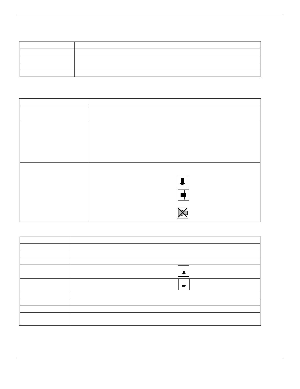
2.1 ISA-60M Exterior Features
The exterior of the instrument is shown in Figure 1. The exterior features are as follows:
Feature Description
Enclosure
Strain Relief
Audio Alarm
Mounting Flanges
2.2 Display ISA-60M Front Panel Features
The display panel, shown in Figure 1, is viewed through the clear front cover of the enclosure, and is accessed by opening the
cover. Features are as follows:
Feature Description
Display
Visual
Alarms & Indicators
Pushbutton Switches
•OPTION Switch
•SELECT Switch
•
AUDIO DEFEAT
A
LARM ACKNOWLEDGE
Switch
/
Engineered thermoplastic, approximately 11x9x6, with a clear hinged front cover.
Entrance for wiring to Remote Sensor
A loud horn activated by certain alarm conditions.
Flanges with holes for mounting the enclosure to a vertical surface.
2 line, 16 character per line, LCD with backlight.
The numerical values of gas concentrations, and other information are displayed.
On either sides of the display:
A red alarm LED for each sensor transmitter installed to the instrument, Alarm 1.
The top center:
A red alarm LED for all sensor transmitters, Alarm 2.
Near the center of the panel:
A green power indicator LED
A red fault alarm LED
There are three of these, located near the center of the panel; they are yellow
rectangular membrane switches. They are:
The top left switch.
Directly to the right of the
OPTION
switch.
Directly below the
OPTION
switch.
2.3 MRI-5175 Features
The exterior and panel of the sensor/transmitter is shown in Figure 1. Internal features are shown in Figure 4.
Feature Description
Enclosure
Strain Relief
Mounting Flanges
MENU Switch
Fiberglass-reinforced polyester with non-magnetic RFI/EMI shielding and hardware
Nickel plated brass, entrance for wiring to ISA-60M control unit
Flanges with holes for mounting the enclosure to a vertical surface.
The left most pushbutton switch
Menu
SELECT Switch
The right most pushbutton switch
Select
Power/Fault LED
Visual Alarm LED
Sensor
Audio Alarm
Red/Green LED, Green indicating power on and red indicating a fault condition
3 Red LED, Triggered at level of alarm
Long life electrochemical oxygen sensor
A loud horn activated by certain alarm conditions.
(Optional)
2
Page 6
ISA-60M ENMET Corporation
O
O
SELECT
OPTION
Alarm Defeat /
Visual Alarm
Mounting Flanges
Visual Alarm
5175
remote sensors are
Punch out/Hole Plug
Audio Alarm
Visual O2
MENU
SELECT
Sensor
Mounting Flanges
Menu
Select
SN:
-XXXX
88
Display
O
2
(
If additional MRI-
connected)
2
%
2
%
Switch
Alarm 2
Switch
Alarm Acknowledge
Switch
For External Wiring
2 places
2 places
Strain Relief
Power/Fault LED
Strain Relief
Alarm LED
Power LED
Front Cover Latch
Fault LED
Audio Alarm
(Nickel Plated Brass)
Power/Fault XXX XXX XXX
Switch
4 places
%O2 by vol.
Figure 1: ISA-60M & MRI-5175 External Features
3
Switch
(Optional)
Page 7
ISA-60M ENMET Corporation
Power Input
Audio
Relay Terminals
Aux Terminals
Primary Detector
4 –
20mA Output
Digital Communication
Hole Plug
s
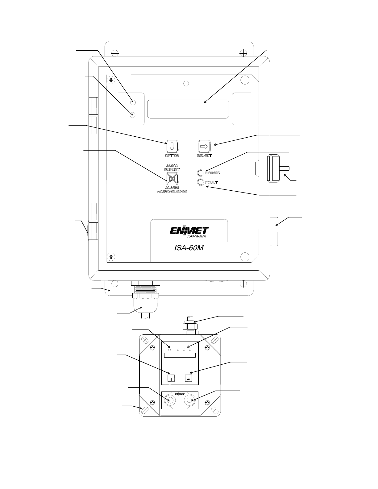
2.3 Circuit Board Features
The Display Panel is hinged on the left and is released by unscrewing the 2 philips screws located in the top and bottom right
corners. After releasing the panel, it is swung to the left, exposing the interior of the enclosure. The Circuit Board is mounted
on a plate at the back surface of the enclosure interior. Features are shown in Figure 2.
Feature Description
Relay Terminals
Output Terminals
(6 places)
This group of terminals is located at the left side of the Circuit Board.
For the contacts for each of four alarm relays, and for the contacts of a fault relay.
There are two for each of the 4-20 mA outputs.
Terminals
4 outputs
2 connectors
Channel 1
Optional (2 places)
Fuse Holder
(2 places)
Ground Screw J21
Terminal J23
Terminals (3 types)
Horn Terminal
Alarm
Strain Relief
Figure 2: ISA-60M Interior Features
4
Page 8
ISA-60M ENMET Corporation
Mounting Holes
Mounting Holes R 0.28” dia.
Menu
Select
SN:
-XXXX
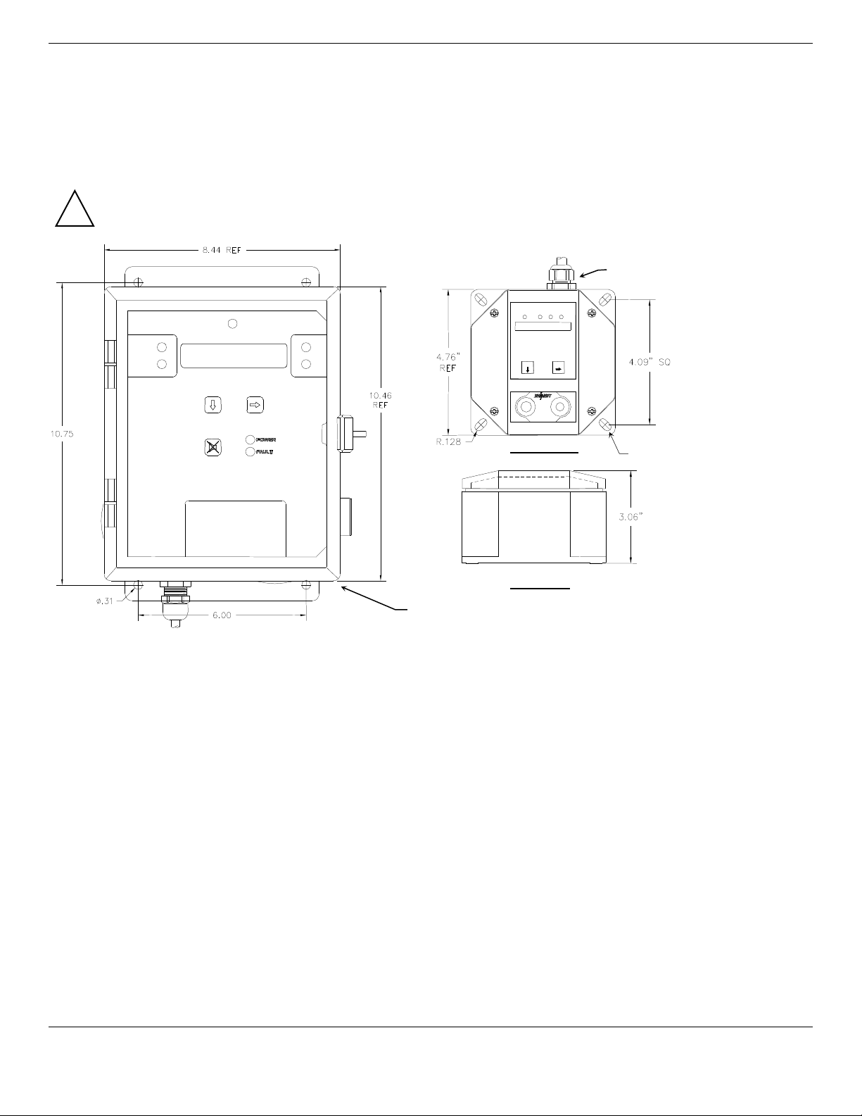
3.0 Installation
3.1 Mounting of Instrument
Mount the ISA-60M and MRI-5175 instrument on an appropriate vertical surface using the mounting flanges provided. Avoid
areas with excessive vibration or temperature extremes. See Figure 3.
It is recommended to use #8 drywall anchors and screws for mounting the ISA-60M and MRI-5175 to a drywall/sheetrock
surface.
Non-magnetic mounting hardware is required for control panels located in the magnet room.
!
Typical location of Strain Relief
Front View
4 places
Side View
0.31” dia. 4 places
Dimensions are in inches.
Figure 3: ISA-60M C
ONTROL &
MRI-5175 R
EMOTE SENSOR
Mounting Dimensions
N
OTE
: Remote Sensor, Each must be connected to a 4-20mA input inside the ISA-60M. UL listed type CM, PLTC or TC cable
shall be used for wiring between the MRI-5175 and the ISA-60M control panel. Three conductor, 18 gauge
for runs up to 1000 feet. For 500 feet or shorter wiring runs, 20 gauge
shielded
wiring is acceptable. The supplied strain
shielded
reliefs are rated for cable with an OD between 0.20 – 0.35 inches.
Refer to Section 7 for Technical Instillation Data.
wiring
5
Page 9

ISA-60M ENMET Corporation
Channel 1, J16
Channel 1, J4
*
Channel 2,
J18
Channel 2,
J4
Channel 3, J19
Channel 3, J4
D–
J4
Shielding wire to Ground S
crew
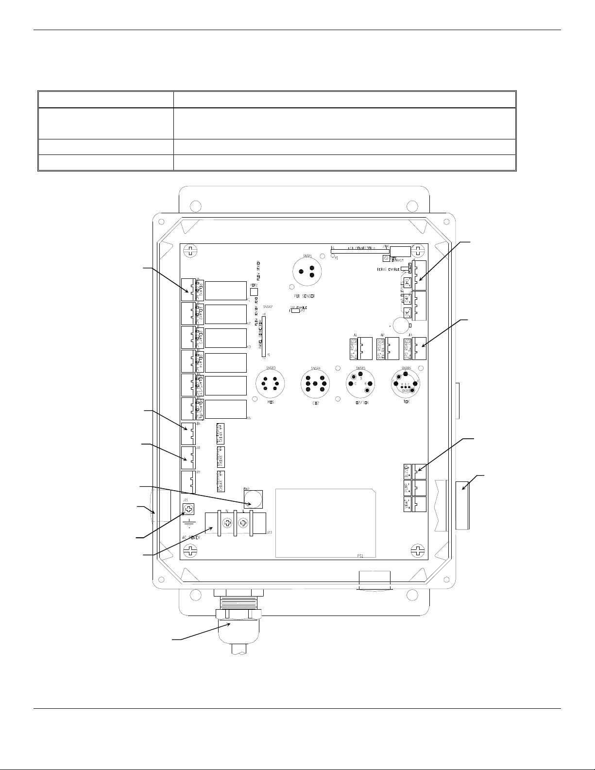
3.2 Wiring ISA-60M to MRI-5175
Wiring for the MRI-5175 alarm, relay contacts and 4-20mA outputs may be routed through one of the two enclosure punchouts on the side or bottom of the enclosure. See Figure 1. Follow state and local guidelines when selecting appropriate strain
relief, conduit and wiring.
Remote Sensor: Each must be connected to a 4-20mA input inside the ISA-60M. UL listed type CM, PLTC or TC cable shall
be used for wiring between the MRI-5175 and the ISA-60M control panel. Three conductor, 18 gauge
runs up to 1000 feet. For 500 feet or shorter
shielded
wiring runs, 20 gauge wiring is acceptable. The supplied strain reliefs
are rated for cable with an OD between 0.20 – 0.35 inches. Refer to Section 7.0 for typical wiring information.
C
AUTION
!
:
Be careful not to scratch or otherwise damage the internal metallic coating of the MRI-5175 during
installation.
Table 1: Wiring ISA-60M to MRI-5175
ISA-60M
D+
mA
GND
24V
+24V (1)
GND (2)
mA (3)
+24V
GND
mA
Power
Ground
Signal
Power
Ground
Signal
*
(Optional)
MRI-5175 Lid, interior view
+24V
GND
mA
Power
Ground
Signal
*
*Shielding wire to Ground Screw of MRI-5175 Ground Screw
shielded
MRI-5175
+24V
GND
mA
+24V
GND
mA
+24V
GND
mA
wiring for
Shield Wire
Ground Screw
MRI-5175 enclosure, interior view
Figure 4: MRI-5175 Ground for Shielded Cable
of MRI-5175 enclosure
6
Page 10

ISA-60M ENMET Corporation
J16 Detector Primary
J18 Connector
J19 Connector
Connector 2 (J4)
Connector 1 (J7)
Power Input, Terminal J23
Channel 3 & 4
4-20mA Output
Channel 1
4-20mA Input
Channel 2
4-20mA Input
Channel 3
Ground Screw J21
Relay 1
Channel 1
Alarm 1
Relay 2
Channel 2
Alarm 1
Relay 3
Channel 3
Alarm 1
Relay 4
Channel 4
Alarm 1
Relay 5
Channel 1-4
Alarm 2
Relay 6
Ch 1-4 / System
Fault
Fuse Holder FH2
L-Line
N-Neutral
Channel 1 & 2
4-20mA Output
Connector RS485
Connector RS232
Connector RS485
Figure 5: ISA-60M Relay and Input and Output Terminals
7
Page 11

ISA-60M ENMET Corporation
Position
Failsafe
-
Alarm
Non-Failsafe
-
Alarm
3.2.1 Outputs
Two types of alarm outputs are available, relay contacts and 4-20mA outputs.
3.2.2 ISA-60M Relay Contacts
Relay contacts are available for each alarm; these are SPDT, rated at 10Amp at 110VAC or 10Amp at 30VDC for restive loads,
and may be latching or non-latching as required by the application. They are accessed on the terminals next to each relay see
Figure 2 & 5. The contact positions are noted on the circuit board next to each terminal.
These relay coils are energized when they are in the non-alarm state; the contact conditions given above are for the nonenergized state, which is identical to the alarm state.
In addition, there is a fault relay, which changes state whenever the instrument is in a fault condition. The contact positions are
noted on the circuit board next to each terminal. The coil of this relay is energized when the instrument is in the non-fault state;
the contact conditions given on the circuit board next to the terminal, are for the non-energized state, which is identical to the
fault state.
The PC Board is labeled for the relays in their un-energized state. If the relay is configured for failsafe, then this is also the alarm
condition state. Non-failsafe configured relays in the alarm state, are the reverse of the PC board labeling. Note that the
Fault(FLT) relay cannot be set to operate in a Non-Failsafe mode. Please see the Table 2 below:
Table 2: Relay Failsafe Settings
J5 Relay 1 - NO Normally Open Normally Closed
J5 Relay 1 - COM Common Common
J5 Relay 1 - NC Normally Closed Normally Open
J6 Relay 2 - NO Normally Open Normally Closed
J6 Relay 2 - COM Common Common
J6 Relay 2 - NC Normally Closed Normally Open
J8 Relay 3 - NO Normally Open Normally Closed
J8 Relay 3 - COM Common Common
J8 Relay 3 - NC Normally Closed Normally Open
J10 Relay 4 - NO Normally Open Normally Closed
J10 Relay 4 - COM Common Common
J10 Relay 4 - NC Normally Closed Normally Open
J14 Relay 5 - NO Normally Open Normally Closed
J14 Relay 5 - COM Common Common
J14 Relay 5 - NC Normally Closed Normally Open
J15 Relay 6/FLT - NO Normally Open N/A
J15 Relay 6/FLT - COM Common N/A
J15 Relay 6/FLT - NC Normally Closed N/A
These relay contacts can be used to operate auxiliary alarms or other functions.
3.2.3 4-20mA Outputs
Isolated 4-20 mA outputs are available for data logging or other purposes. An output is supplied for each sensor supplied in a
particular instrument, and can be added when a sensor is added in the field. These outputs are available on the Connector 1(J7)
for channels 1 & 2 and Connector 2(J4) for channels 3 & 4.
4mA corresponds to the sensor reading of 0 at the bottom of the range.
20mA corresponds to a full scale reading of 30.
Wiring requirements are the same as for the relays.
3.2.4 Digital Outputs
The RS232 & RS485 connections are used for firmware updates and digital communications. The ISA-60M is designed to
operate as a modbus slave. Contact the ENMET for further information on wiring for the digital outputs.
8
Page 12

ISA-60M ENMET Corporation
!
J16 D
etector Primary
J18 Connector
J19 Connector
Connector 2 (J4)
Connector 1 (J7)
Power Inp
ut, Terminal J23
Channel 3 & 4
4-20mA Output
Channel 1
4-20mA Input
Channel 2
4-20mA Input
Channel 3
Ground Screw J21
Relay 1
Channel 1
Alarm 1
Relay 2
Channel 2
Alarm 1
Relay 3
Channel 3
Alarm 1
Relay 4
Channel 4
Alarm 1
Relay 5
Channel 1-4
Alarm 2
Relay 6
Ch 1-4 / System
Fault
Fuse Holder FH2
L-Line
N-Neutral
Channel 1 & 2
4-20mA Output
Connector RS485
Connector RS232
Connector RS485
Figure 5: ISA-60M Relay and Input and Output Terminals
3.3 Power Supply
The input power can vary from 100 to 240VAC, 50/60 Hz. Mains power should be connected to the Power Input Terminal J23
and the ground screw J21. See Figure 5 for location.
W
ARNING
:
Continuous gas detection and alarm systems become inoperative upon loss of primary power.
Upon supplying power to the ISA-60M:
The green power on LED is lit.
The display backlight is lit, and instrument will step through a start-up sequence: unit serial number, software revision
and gases monitored may be shown on the display.
The instrument may go into alarm briefly, but the sensors stabilize quickly. If the instrument persists in alarm, acknowledge the
alarm by pressing the A
UDIO DEFEAT /ALARM ACKNOWLEDGE
switch. If alarm persists longer than 30 minutes, call ENMET
customer service personnel.
Mains power line is fused for power supply protection. Fuse is 5 x 20mm, 0.630Amp is located in FH2, see Figure 5
3.5 Initial Calibration
All instruments are calibrated at the factory. You may, if a calibration kit is available, calibrate the MRI-5175
3 – 4 hours after installation. See Section 5.0, Maintenance, for calibration instructions.
9
Page 13

ISA-60M ENMET Corporation
O2 20.9
O
%
4.0 Operation
4.1 Normal Operation Condition
With the ISA-60M installed as described in Section 3, and in clean air, the POWER green LED is on, the display is lit, and the
information on the display is as shown in Figure 6, for the sensor(s) installed in the ISA-60M. The red alarm and fault LEDs
are not lit.
2
Example of display
Figure 6: ISA-60M Operational Display
4.2 Alarm Set Points
There are two alarm set points for each active oxygen channel. They are adjustable from 16.0 to 24.9. The standard factory
settings of these alarm set points are:
Alarm 1 is 19.5 % by volume, indicated by Flashing LED and audio alarm.
Alarm 2 is 17 % by volume, indicated by Steady LED and alarm 1 LED changes from flashing to steady.
These alarm set points can be changed within limits; see the maintenance section of this manual for the procedure.
If the oxygen content of the sample air decreases below an alarm set point, the associated red LED activates, the associated
relay changes state, and the audio alarm is activated.
Differential Setting (Non Factory)
Differential is an optional alarm relay configuration where when an alarm has been triggered, the relay will remain in alarm
state until the sensor reading has moved the differential “value” in the non-alarm direction. See example below.
The Alarm 1 differential value is the delay of the ISA-60M staying in alarm condition until after the measured reading has
returned past the alarm point by the differential value. Example: If the alarm point is V 19.5 and the differential is 2, the
ISA-60M will go into alarm at 19.5 and stay in alarm until the reading has risen above 19.7.
C
AUTION
: Setting the alarm points to the differential setting disables the audio alarm for alarm point 1. The differential Setting
has no effect on alarm relays or on the audio alarm for alarm point 2.
4.3 Fault Indications
Fault indications are associated with sensor zero and calibration activities, and are described in the maintenance section 5.0 of
this manual.
4.4 Alarm Latching
An instrument is shipped with the alarms in the latching mode. The alarms may be independently configured in the nonlatching mode or differential setting by use of the maintenance menu. See Section 5.2.2, for setting alarm 1 and alarm 2.
Standard Setting
I
N THE LATCHING MODE
alarm relay contacts do not revert to the non-alarm state, until the ALARM ACKN/AUDIO DEFEAT switch is pressed. An
alarm can also be acknowledged by pressing the switch during the alarm condition; then at the cessation of the alarm
condition, alarm indications cease and alarm relays revert to the non-alarm state. After an alarm is acknowledged, alarms in
the latching configuration are re-armed to latch at the next alarm condition.
I
N THE NON-LATCHING MODE
cease, and the alarm relay contacts revert to the non-alarm state.
: at the cessation of the condition which causes an alarm, the alarm indications do not cease, and the
: at the cessation of the condition that causes an alarm, the alarm indications automatically
4.5 Audio Defeat
Pressing the
60M not on the MRI-5175. Relays and alarm LEDs continue to function, in the alarm state, during an alarm condition. As
long as the alarm condition persists, the audio alarm will “chirp” every 20 seconds. After the alarm condition clears, the audio
will continue to “chirp” until the audio switch is pressed.
If after 15 minutes the alarm condition continues the audio alarm will reactivate at full intensity.
If any other alarm condition occurs while the audio alarm has been silenced it will force the audio alarm to reactivate
immediately.
AUDIO DEFEAT / ALARM ACKNOWLEDGE
switch during an alarm temporarily silences the audio alarm on the ISA-
10
Page 14

ISA-60M ENMET Corporation
O
S
4.6 Display
In clean air a display is shown in Figure 6. This position of the display is termed the "operational display". As explained below,
the display can be changed to furnish other information by using the OPTION and SELECT switches.
Oxygen concentration is given in percent by volume.
4.7 Operational Menu
The operational menu allows the user to:
View alarm set point concentration values
View alarm latching configurations
Enter the maintenance menu with the proper Password.
The operational menu is accessed with the OPTION and SELECT switches. The operational menu flow chart is shown in
Figure 7,
Pressing the OPTION switch is indicated with a "O"
Pressing the SELECT switch is indicated with a "S".
If the instrument is left at any location in the operational or maintenance menus, other than the operational display, with no
action taken for a period of 45 seconds, it returns to the operational display.
CH-1 CH-3
CH-2
S
No
Function
O
Relays 123456
6=ON
O
CH1 SCALE (O2)
0.0 – 30.0%
O
vL19.5 A1 vL19.5
vD 19.5
O
vL17 A2 v17
vD17
No
S
Function
S
for each active channel
CH2 SCALE (O2)
O
0.00 – 30.0%
S
O
CH3 SCALE
0.0 – 30.0 %
S
No
S
Function
No
S
Function
(O2)
Displays are examples:
6 – Indicates relay is engaged
Displays are examples of Alarms
Λ
- Indicates alarm triggered on increasing
value of reading
v - Indicates alarm triggered on decreasing
value of reading
Displays are examples of Alarms
L – Indicates alarm is in latching mode. Note:
Factory setting for alarms is latching
(no L present) – Indicates alarm is in non-
latching mode.
Displays are examples of Alarms
D – Indicates alarm is in Differential Setting.
(no D present) – Indicates alarm is in Standard
Setting.
O
ALARM1 Delays
(Seconds)
Alternating
5 5
5 5
No
S
Function
O
30 mASPAN 30.0
30
No
S
Function
O
O = Press Option switch
S = Press Select switch
Enter Maint Menu
Enter Password
_
See Maintenance Menu Diagram
Figure 7: ISA-60M Operation Menu Flow Chart
11
Page 15

ISA-60M ENMET Corporation
!
5.0 Maintenance
The ISA-60M has no specific preventative maintenance requirements. Entering the maintenance menu, as outlined in Section
5.2 may change instrument configurations.
The MRI-5175 sensor will require periodic calibration and replacement. Oxygen sensor calibration should be preformed on at
least a quarterly basis. The sensor has an estimated lifetime of 5 years. The sensor should be replaced when it will not calibrate
or shortly before the 5 year time frame, to ensure continuous instrument operation. Sensor calibration instructions can be found
in Section 6.0.
5.1 Cleaning Instructions
C
AUTION
5.2 Maintenance Menu ISA-60M
: Never spray a cleaning solution on the surfaces of the ISA-60M or MRI-5175 devices.
Clean the exterior of the ISA-60M and MRI-5175 enclosures with a mild soap solution on a clean, damp cloth. Do not soak
the cloth with solution so that moisture drips onto, or lingers on, external surfaces.
Under no circumstances should organic solvents such as paint thinner be used to clean instrument surfaces.
The maintenance menu diagram is shown in Figure 8 Maintenance Menu Flow Chart. From the operational display, press
the OPTION switch 4 times; "Enter MAINTENANCE Menu" is displayed.
O = Press Option
S = Press Select
Figure 8: ISA-60M Maintenance Menu Flow Chart.
12
Page 16

ISA-60M ENMET Corporation
5.2.1 Set 4 –20mA Transmitter Scale
This section of the maintenance menu is for aligning the external sensor/transmitters MRI-5175 to the ISA-60M controller.
This function is normally performed at the factory and is not usually required in the field unless a new transmitter is installed.
5.2.2 MRI-5175 Calibration
Calibration is performed at the MRI-5175 remote sensor/transmitter.
Calibration is the process of setting the instrument up to read accurately when exposed to a target gas.
Wait at least 3 – 4 hours after initially supplying power to the MRI-5175 sensor/transmitter before calibration, Overnight
stabilization is preferred before calibration. The MRI-5175 has been pre-calibrated at the factory, and initial field calibration
should result in only fine tuning the circuit, as well as a way to check that installation is successful. It is not necessary to open
the enclosure to make adjustment. The calibration functions are operated through the
for Power/Fault LED Sequence codes and Figure 9 Calibration MRI-5175.
MENU
and
SELECT
switches. See Table 5
5.2.3 Standard Calibration
The following procedure is suitable for altitudes below 4500 ft (1372 meters):
1. Press and hold the Menu switch for 3 to 5 seconds, the Power /Fault led will flash red- green, red- green, red- green….
2. Assemble the cylinder flow regulator and MRI calibration adapter.
To calibrate:
3. Press and release the Menu switch, then press and release the Select switch. This places the transmitter into the calibration
Span operation. The Power/ Fault led will flash Green-red-red-red, Green-red-red-red…
4. Attach the MRI calibration adaptor, part number 03620-021 to the sensor, then pull the trigger on the cylinder of 20.9%
Oxygen part number 03100-029 and partially inflate the bellows.
5. The MRI-5175 transmitter begins to look for signal stabilization; this process lasts from 60 to 120 seconds.
Observe the Power/ Fault led during this time. When the signal has stabilized, the Power/Fault led will show green for 3
seconds, indicating a successful calibration, and then flash red-green, red-green… If the calibration was unsuccessful,
following the 60 to 120 second stabilization time the Power/Fault led will show Red for 3 seconds and then flash red-green,
red-green, red-green…
6. Press and release the Select switch to exit calibration and return to operation mode. If the calibration was completed
successfully the Power/Fault led will show steady Green. If the calibration Failed the Power/Fault led will flash a Slow redgreen, red-green… Continue to flow the 20.9 Oxygen. Go to Section 5.2.5
5.2.4 Altitude Calibration
This procedure is required for altitudes above 4500 ft (1372 meters). Due to the reduction of partial pressure at elevations above
4500 ft (1372 meters), the following procedure must be used when installing the ISA-60M monitor. Subsequent calibration
should be done using the Standard calibration procedure as the compensation for partial pressure variances will have been
accomplished.
1. Press and hold the Menu switch for 3 to 5 seconds, the Power /Fault led will flash red- green, red- green, red- green…
2. Assemble the cylinder flow regulator and MRI calibration adapter.
To calibrate:
3. Press and hold the Menu switch for 3 to 5 seconds, the Power /Fault led will flash red, red, red, red …
4. Press and release the Menu switch then press and release the Select switch. This places the transmitter into the calibration
Span operation. The Power/ Fault led will flash Green-red-red-red, Green-red-red-red…
5. Attach the MRI calibration adaptor to the sensor, then pull the trigger on the cylinder and partially inflate the bellows.
6. The MRI-5175 transmitter begins to look for signal stabilization; this process lasts from 60 to 120 seconds.
Observe the Power/ Fault led during this time. When the signal has stabilized, the Power/Fault led will show green for 3
seconds, indicating a successful calibration, and then flash red-green, red-green and then red, red, red… If the calibration
was unsuccessful, following the 60 to 120 second stabilization time the Power/Fault led will show Red for 3 seconds and then
flash red-green, red-green, red-green…
7. Press and release the Select switch to exit calibration and return to operation mode. If the calibration was completed
successfully the Power/Fault led will show steady Green. If the calibration Failed the Power/Fault led will flash a Slow redgreen, red-green… Continue to flow the 20.9 Oxygen Go to Section 5.2.5
NOTE: After the initial Altitude Calibration, subsequent calibrations should be done following the Standard Calibration procedure.
13
Page 17

ISA-60M ENMET Corporation
Example:
Table 3: Set up values
Gas 4mA
20mA
MENU Switch
SELECT Switch
Calibration Cover
Menu
Select
Power/
Fault XXX
XXX
XXX
%O2 b y vol.
11Liter
Aerosol
Gas
Cylinder Assembly
Calibration Cover
Connection to
Flow Regulation Bellows
Valve/Regulator
Calibration
Select O2
MAINTENANCE MENU
Scale
m
Xmtrs
Press
O
CH1
O2 mA XMTER
4m
= 0.0
each digit
CH1
O2 mA XMTER
20mA
=
CH1: O2 mA
mA Trim ?
O2 : 20.5 3030
Trim Val: 20.9
Trim OK
Trim Error
S
Example
Table 5: Fault LED Code Sequence
Power/Fault LED Code Indication Sequence
Exit Green-red – green-red – green red-…
Span Green-red-red-red – green-red-red-red – green-red-red-red…
Cal OK Green for 3 seconds
Bad Cal Red for 3 seconds
Power/Fault LED
(Included with Cylinder)
Calibration Cover
(03620-021)
on Sensor
Figure 9: Calibration MRI-5175
5.2.5 ISA-60M Controller
Entering a valid password into maintenance menu, the Scale mA Xmtrs section is the second menu section, if it is installed,
enter by pressing the S
Press the SELECT switch "mA Xmter Scale: Select Ch1:O2" is displayed.
Press the OPTION switch, if needed, to change the channel to be set up.
Press the SELECT switch, “Ch#: mAXmter: 4mA: 00” is displayed
Press the SELECT switch, that moves the cursor one digit to the right when the last digit is accepted the display move to
the full Scale mA Xmtrs menu, the display reads
Press the SELECT switch, which moves the cursor one digit to the right when the last digit is accepted the display will
read “Ch#:O2 mAXmter NA Trim?”
Press the SELECT switch to enter. The display will read “O2:20.8, 3029,Trim Val:20.7?” (note this number will vary)
Press the SELECT switch, to move the cursor, use the OPTION switch to adjust the numbers to 20.9
Repeat these steps for each 4 –20mA transmitter.
Press the OPTION switch, to continue on to the next section of the Maintenance Menu.
ELECT
switch
Sensor/Transmitter Set Up Flow Chart
O
S
S
O
O
S
PTION
Up is displayed
XMTER
14
until the channel to be Set-
each digit
S
S
each
O
2
0 30
Page 18

ISA-60M ENMET Corporation
5.2.6 Set Alarm Points
Factory alarm set points are discussed in Section 4.2, See Table 2. To change the alarm points, you must enter the maintenance
menu.
N
OTE
: Changing the alarm points on the ISA-60M will NOT change the alarm points on the MRI-5175 sensor transmitter.
Entrance to the maintenance menu is guarded with a four-digit Password. The factory default setting of the password is 1270.
When a valid numerical password is inserted, the user is allowed to enter the maintenance menu.
In the "Enter Maint Menu" position
Press the
will be the first digit of the password.
In the T000 position, the underline cursor is under the left digit.
Press the
Press the
Continue this process until the four-digit password is complete. When a valid password is inserted in this manner, the display is
transferred to the "Calibration" portion of the menu. If an invalid password is inserted you are returned to the Enter Maint
Menu display.
After entering a valid password:
Press the
Press the
Press the
Λ
for ascending trigger point or V for descending trigger point indicator.
Press the
Press the
Press the
Press the
IF: STD is selected, "ALARM 1 V L " is displayed.
The next character is the latching indicator L or NOL press the
The next characters are the alarm 1 value, press the
When the last digit is accepted display returns to the Maintenance Menu "Set Alarm1" position.
IF: DIFF is selected, "ALARM 1
The next characters are the alarm 1 value, press the
Move the cursor to the first digit and, Press the
right.
"ALARM 1
Press the
Note: The Alarm 1 differential value is the delay of the ISA-60M staying in alarm condition until after the measured reading
has returned past the alarm point by the differential value. Example: If the alarm set point is V 19.5 and the differential is 2,
the ISA-60M will go into alarm at 19.5 and stay in alarm until the reading has risen above 19.7.
Repeat the above procedure for each sensor alarm 1 to be changed.
Press the
Repeat as for alarm 1 using the STD section. Alarm Diff is not available for Alarm 2.
Press
Display
C
AUTION
SELECT
OPTION
SELECT
OPTION
SELECT
SELECT
OPTION
SELECT
OPTION
SELECT
OPTION
OPTION
OPTION
switch "Enter Password T 0" is displayed. Press
SELECT
switch once, to move cursor to next digit, this
switch to change the left digit; select the correct digit.
switch, which locks the digit in place and moves the cursor one digit to the right.
switch until; “Maintenance Menu Set Alarm1” appears on display.
switch, "ALARM1 Select: O2" is displayed.
switch; "ALARM 1 V " is displayed, with the indicator flashing,
switch to toggle between Λ and V; select the correct indicator.
switch to lock in the correct indicator. "ALARM 1
STD
" is displayed
switch to toggle between STD and DIFF; select the correct indicator.
switch to lock in the correct indicator.
DIFF BAND 0.0
OPTION
V DIFF 19.5
OPTION
" is displayed, Factory default setting.
OPTION
SELECT
switch to select each digit of the value
switch to select each digit of the value
switch to lock in the correct character and move the cursor to the
" is displayed, to set alarm 1 differential. With
switch to toggle the latching mode.
SELECT
switch move cursor to left.
switch to select each digit of the value.
switch to move to alarm 2, "Set ALARM2" is displayed.
switch until “Exit maint menu” appears, then press
SELECT
switch to return the instrument to the Operational
: Setting the alarm points to the differential setting disables the audio alarm for alarm point 1. The differential Setting
has no effect on alarm relays or on the audio alarm for alarm point 2.
15
Page 19

ISA-60M ENMET Corporation
O
S
S
MAINTENANCE MENU
Set Alarm1
Alarm 1 -
Select: O2
v
Alarm 1
O
S
D
Locks selection
S
Alarm 1 DIFF
BAND
0
00
v L–19.5
Alarm 1
O
S
S
S
v
Alarm 1
O
S
Locks selection
S
TL
Alarm 1
O
S
Locks selection
Alarm 1
DIFF
1
9.5
S
S
O
S
O
S
Alarm 2 -
Select:
XX
MAINTENANCE MENU
Set Alarm2
Changes character indicated by underscore cursor
Locks underscored character and moves cursor to next
O
Press
O
until the channel to be
Set
is displayed
Alarm 2
V L 0
000
Example: Set Alarms Flow Chart
Displays shown are factory default settings.
Λ -
Indicates alarm triggered on increasing value of reading
v
-
Indicates alarm triggered on decreasing value of reading
L-
Indicates alarm is set for latching
NO
L-
Indicates alarm is set for non-latching
O = Press Option
S = Press Select
STD – Indicates alarm in standard setting, can be set in latched or non-latched mode
DIFF – Indicates alarm in differential setting, instrument will stay in alarm beyond the alarm set point by the differential value
Toggles status between Λ increasing trigger and v decreasing trigger
T
Toggles status between Standard and
STD
DIFF
S
TD
Toggles status between
V
Latching and Non Latching
Changes character indicated
by underscore cursor
Locks underscored character and
moves cursor to next digit
PTION
v
IFF
Changes character indicated by
O
underscore cursor
Locks underscored character and
moves cursor to next digit
Changes character indicated by
O
underscore cursor
Locks underscored character and
moves cursor to next digit
16
Page 20

ISA-60M ENMET Corporation
Example:
Example:
Channel 1
Channel 2
Channel 3
Channel 4
O
S
MAINTENANCE MENU
Set Alarm Delays
S
O
S
Alarm Delay -
Changes digit indicated by underscore cursor
Locks underscored digit and moves cursor to next digit
O
Select:
XX
Alarm Delay -
0
000
O
S
MAINTENANCE MENU
Configure Alarms
S
O
S
Ch 1,2,3,4
Changes digit indicated by underscore cursor
Locks underscored digit and moves cursor to next digit
O
R1
L
Ch 1 2 3 4
R2
L
5.2.7 Set Alarm “Delay On”
The alarms may be set to delay activation by 1 second increments.
Factory set default value is 5 seconds.
After entering a valid password:
Press the OPTION switch until; “Maintenance Menu Set Alarm Delay” appears on display.
Press the SELECT switch, "ALARM Delay Select: O2" is displayed.
Press the SELECT switch; "ALARM Delay = T005" is displayed, with the underscore cursor under the left position.
Press the SELECT switch to move the cursor and the OPTION switch to lock in the correct digit and move the cursor
one digit to the right. Press the SELECT switch when the last digit is accepted display returns to the "Set Alarm Delay"
position.
Press the OPTION switch to continue on to the Set New Password section
Set Alarm Delay Flow Chart
Press Option until the channel to be
is displayed
Set
5.2.8 Relay Configuration
To change a relay configuration you must enter the maintenance menu. Press the
is displayed then press
SELECT
switch for the Enter Password menu. Enter the valid password as described below.
In the "Enter Maint Menu" position
Press the
SELECT
switch "Enter Password T 0" is displayed. Press
this will be the first digit of the password.
In the T000 position, the underline cursor is under the left digit.
Press the
Press the
OPTION
SELECT
switch to change the left digit; select the correct digit.
switch, which locks the digit in place and moves the cursor one digit to the right.
Continue this process until the four-digit password is complete. When a valid password is inserted in this manner, the
display is transferred to the "Calibration" portion of the menu. If an invalid password is inserted you are returned to the
Enter Maint Menu display.
After entering a valid password:
Press the
OPTION
switch until “Configure Alarms” is displayed
L = Low Alarm = Alarm 1, H = High Alarm = Alarm 2, B = Both Alarms, = No Relay linked to channel
Set Relay Configuration Flow Chart
Press Option changes letter indicated by underscore cursor
SELECT
OPTION
switch until “Enter Maint Menu”
switch once, to move cursor to next digit,
O = Press Option
S = Press Select
The Table 4 below shows the default relay links.
Relay 1 Low Alarm
Relay 2 Low Alarm
Relay 3 Low Alarm
Relay 4 Low Alarm
Relay 5 High Alarm High Alarm High Alarm High Alarm
Relays can be linked to specific alarms.
N
OTE
: Each operating channel must be linked to at least 1 relay.
Table 4: Default Relay Links
17
Page 21

ISA-60M ENMET Corporation
Example:
Example:
MAINTENANCE MENU
Set New Password
Password
T
0000
OFF
5.2.9 Failsafe Configuration
The ISA-60M is factory set in a failsafe configuration. This means that if power is disconnected to the unit, or the relay
fails to properly engage, it fails in such a way that it is in the alarm position. ENMET recommends leaving the relay in a
failsafe configuration. However, relay 1 – 5 can be re-configured by using the following procedure.
To change a relay failsafe configuration you must enter the maintenance menu. Press the
Menu” is displayed then press
SELECT
switch for the Enter Password menu. Enter the valid password as described below.
In the "Enter Maint Menu" position
Press the
SELECT
switch "Enter Password T 0" is displayed. Press
SELECT
this will be the first digit of the password.
In the T000 position, the underline cursor is under the left digit.
Press the
Press the
OPTION
SELECT
switch to change the left digit; select the correct digit.
switch, which locks the digit in place and moves the cursor one digit to the right.
Continue this process until the four-digit password is complete. When a valid password is inserted in this manner, the
display is transferred to the "Calibration" portion of the menu. If an invalid password is inserted you are returned to the
Enter Maint Menu display.
After entering a valid password:
Press the
OPTION
switch until “Relay Failsafes” is displayed
Set Relay Failsafe Configuration Flow Chart
MAINTENANCE MENU
Relay Failsafes
S
R: 1 Failsafe ON
Relay Failsafes
Pressing O
O
PTION
changes Failsafe setting from ON to OFF
S
O
Relay Failsafes
R: 2 Failsafe
O
Changes
S
Continue pressing S
Failsafe setting from ON to OFF
ELECT
to cycle through all 5 relays
switch once, to move cursor to next digit,
OPTION
switch until “Enter Maint
O = Press Option
S = Press Select
5.2.10 Set New Password
To change the password, you must enter the maintenance menu. Press the
then press
SELECT
switch for the Enter Password menu. Enter the valid password as described in Section 5.2.1.
To set a new password, after inserting a valid password,
Press the
Press the
Use the
Press the
OPTION
SELECT
OPTION
SELECT
switch until; "Set New Password” is displayed.
switch; "Password T1270" is displayed, with the underscore cursor under the left digit.
switch to change the left digit, when the desired digit is displayed.
switch to lock the digit in place and move the cursor one digit to the right.
When all four digits of the new password have been selected, "Set New Password" is displayed.
Record the new password; without it, the maintenance menu cannot be reentered once you exit the Maintenance Menu. If the
password is lost, call ENMET customer service personnel.
From the "Password XXXX" position,
Press the
Press the
SELECT
OPTION
switch to return to Set New Password section.
switch; to continue to "exit MAINTENANCE Menu"
Set Password Flow Chart
S
O
Changes digit indicated by underscore cursor
S
Locks underscored digit and moves cursor to next digit
O
OPTION
switch until “Enter Maint Menu” is displayed
O = Press Option
S = Press Select
18
Page 22

ISA-60M ENMET Corporation
Example:
S
5.2.11 Exit Maintenance Menu
From the "exit MAINTENANCE Menu" position
Press the SELECT switch to resume the operational display.
Press the OPTION switch to reenter the maintenance menu at the "Calibration" position.
Exit Maintenance Menu Flow Chart
MAINTENANCE MENU
Exit maint menu
CH-1 CH-3
CH-2
MAINTENANCE MENU
Calibration
O
5.3 MRI-5175 Sensor Transmitter
The MRI-5175 is supplied with 3 alarm points:
2 are factory set to match the ISA-60M
The 3rd is set at 23.5 as an oxygen abundance indicator.
The alarm points are not field adjustable.
When equipped with an audio alarm for safety reasons this alarm can not be silenced when triggered by an unsafe condition.
5.4 Channel Activation/Deactivation
Each channel of the ISA-60M can be deactivated and activated as needed.
C
AUTION
: Deactivated channels will not display or respond to connected sensor transmitters.
A fault indication occurs when a transmitter is not connected to an active channel of the ISA-60M.
To Activate or deactivate a channel of the ISA-60M:
Enter the maintenance menu as described in Section 5.2 and press the
Press and Hold the
Press the
Press the
Press the
Press the
SELECT
OPTION
SELECT
SELECT
OPTION
switch until “ADV maint menu” is displayed.
switch to locate the channel to be changed.
switch to change the status of that channel.
switch to accept the change in status. “ADV maint menu Exit” is displayed.
switch to return to the operational menu.
OPTION
switch until Exit maint menu appears.
19
Page 23

ISA-60M ENMET Corporation
6.0 Maintenance MRI-5175
The MRI-5175 sensor will require periodic calibration and replacement. Oxygen sensor calibration should be preformed
quarterly, but not less than annually. The sensor has an estimated lifetime of 5 years. The sensor should be replaced when it
will not calibrate or shortly before the 5 year time frame, to ensure continuous instrument operation.
6.1 MRI-5175 Calibration
Calibration is performed at the MRI-5175 remote sensor/transmitter.
Calibration is the process of setting the instrument up to read accurately when exposed to a target gas.
Initial Calibration: Wait at least 3 – 4 hours after initially supplying power to the MRI-5175 sensor/transmitter before initial
calibration, Overnight stabilization is preferred before calibration. The sensor has been pre-calibrated at the factory, and initial
field calibration should result in only fine tuning the circuit, as well as a way to check that installation is successful. It is not
necessary to open the enclosure to make adjustment. The calibration functions are operated through the
switches. See Table 5 for Power/Fault LED Sequence codes.
ENMET Corporation recommends quarterly, but not less than annual, calibration of the MRI-5175 transmitters.
6.1.1 Standard Calibration
The following procedure is suitable for altitudes below 4500 ft (1372 meters):
1. Press and hold the Menu switch for 3 to 5 seconds, the Power /Fault led will flash red- green, red- green, red- green….
2. Assemble the cylinder flow regulator and MRI calibration adapter.
To calibrate:
3. Press and release the Menu switch, then press and release the Select switch. This places the transmitter into the calibration
Span operation. The Power/ Fault led will flash Green-red-red-red, Green-red-red-red…
4. Attach the MRI calibration adaptor, part number 03620-021 to the sensor, then pull the trigger on the cylinder of 20.9%
Oxygen part number 03100-029 and partially inflate the bellows.
5. The MRI-5175 transmitter begins to look for signal stabilization; this process lasts from 60 to 120 seconds.
Observe the Power/ Fault led during this time. When the signal has stabilized, the Power/Fault led will show green for 3
seconds, indicating a successful calibration, and then flash red-green, red-green… If the calibration was unsuccessful,
following the 60 to 120 second stabilization time the Power/Fault led will show Red for 3 seconds and then flash red-green,
red-green, red-green…
6. Press and release the Select switch to exit calibration and return to operation mode. If the calibration was completed
successfully the Power/Fault led will show steady Green. If the calibration Failed the Power/Fault led will flash a Slow redgreen, red-green…
MENU
and
SELECT
6.1.2 Altitude Calibration
This procedure is required for altitudes above 4500 ft (1372 meters). Due to the reduction of partial pressure at elevations above
4500 ft (1372 meters), the following procedure must be used when installing the ISA-60M monitor. Subsequent calibration
should be done using the Standard calibration procedure as the compensation for partial pressure variances will have been
accomplished.
1. Press and hold the Menu switch for 3 to 5 seconds, the Power /Fault led will flash red- green, red- green, red- green…
2. Assemble the cylinder flow regulator and MRI calibration adapter.
To calibrate:
3. Press and hold the Menu switch for 3 to 5 seconds, the Power /Fault led will flash red, red, red, red …
4. Press and release the Menu switch then press and release the Select switch. This places the transmitter into the calibration
Span operation. The Power/ Fault led will flash Green-red-red-red, Green-red-red-red…
5. Attach the MRI calibration adaptor to the sensor, then pull the trigger on the cylinder and partially inflate the bellows.
6. The MRI-5175 transmitter begins to look for signal stabilization; this process lasts from 60 to 120 seconds.
Observe the Power/ Fault led during this time. When the signal has stabilized, the Power/Fault led will show green for 3
seconds, indicating a successful calibration, and then flash red-green, red-green and then red, red, red… If the calibration
was unsuccessful, following the 60 to 120 second stabilization time the Power/Fault led will show Red for 3 seconds and then
flash red-green, red-green, red-green…
7. Press and release the Select switch to exit calibration and return to operation mode. If the calibration was completed
successfully the Power/Fault led will show steady Green. If the calibration Failed the Power/Fault led will flash a Slow redgreen, red-green…
NOTE: After the initial Altitude Calibration, subsequent calibrations should be done following the Standard Calibration procedure.
20
Page 24

ISA-60M ENMET Corporation
Sensor Wires
MENU Switch
SELECT Switch
Calibration Cover
Menu
Select
Power/
Fault XXX
XXX
XXX
%O2 b y vol.
11Liter Aerosol
Gas
Cylinder Assembly
Calibration Cover
Connection to
Flow Regulation Bellows
Valve/Regulator
Table 5: Fault LED Code Sequence
Power/Fault LED Code Indication Sequence
Exit Green-red – green-red – green red-…
Span Green-red-red-red – green-red-red-red – green-red-red-red…
Cal OK Green for 3 seconds
Bad Cal Red for 3 seconds
Power/Fault LED
(Included with Cylinder)
Calibration Cover
(03620-021)
on Sensor
N
OTE
: If the calibration process indicates a failure, wait 30 minutes and repeat process or contact ENMET Corporation.
Figure 9: Calibration MRI-5175
6.2 Sensor Replacement
An Oxygen sensor must be replaced when it can no longer be calibrated. Typical sensor life is 3 to 5 years in a 20.9% oxygen
environment.
To replace a sensor, perform the following steps:
Turn off the electrical power.
Open the display panel and remove the four cover (lid) retention screws and remove the lid. See Figure 10.
Remove the old O2 sensor, by unscrewing it, and replace it with a new sensor. See Figure 10.
Replace cover(lid) with retention screws.
Turn on the electrical power.
Wait 3 – 4 hours, then recalibrate the sensor per the instructions in Section 6.1.
O2 Sensor
To J8
MRI-5175 Exterior View
Figure 10: MRI-5175 Sensor Replacement
Terminal J8
(Optional)
MRI-5175 Lid, Interior View
Sensor Wiring
J8 Sensor Wires
V+
Sig
Gnd
21
Not Used
Red wire
Black wire
Page 25

ISA-60M ENMET Corporation
Mechanical
Outputs
Shielding wire to Ground Screw
See Figure 4
7.0 Technical Data and Specifications
Electrical Power
Storage and Transport
Operation
ISA-60M
MRI-5175
ISA-60M
MRI-5175
Example of controller to MRI-5175 wiring
15 Amp fused branch circuit
100-240 VAC
0.9 A
50/60 Hz
Board Mounted Fuse FH2, 0.630A, 5 x 20mm
(to also be included on shipping box)
Temperature:
preferred
Relative Humidity
Atmospheric Pressure
Temperature:
Relative Humidity
Atmospheric Pressure
Dimensions:
Weight:
Strain relief:
Material:
Dimensions:
Weight:
Strain relief:
Material:
Relays: SPDT
Analog: 4-20 mA x 3
Digital: RS-232 – Modbus
Audio: 90 db at 2 ft
Analog 4-20 mA
Digital: RS-485 – Modbus
Audio: 90 db at 2 ft
-20° to +60°C (-4° to +140°F)
0° to +20°C (32° to 68°F)
10-99% RH, non-condensing
20 to 36 inHg (68 to 133 kPa)
0° to +40°C (32° to +104°F)
10-99% RH, non-condensing
20 to 36 inHg (68 to 133 kPa)
11 x 9 x 6 inches (4.3 x 3.5 x 2.4 cm)
8 lbs (3.6 kg)
5 – 12 mm OD
Engineered thermoplastic with hinged front cover
Non-magnetic hardware
5 x 5 x 4 inches (2 x 2 x 1.6 cm)
2 lbs (0.9 kg)
5 – 12 mm OD
Fiberglass-reinforced polyester with Non-magnetic
RFI/EMI shielding and hardware
Resistive Load Inductive Load
10A at 110 VAC 7.5A at 110 VAC
10A at 30 VDC 5A at 30 VDC
RS-485 – Modbus
N
OTE
: All specifications stated in this manual may change without notice.
22
of MRI-5175 enclosure
Page 26

ISA-60M ENMET Corporation
8.0 Replacement Part Numbers
ENMET part numbers for replacement parts:
Part number Description
67016-1152 Sensor, Oxygen
64002-630 Fuse, 0.630 Amp 5x20mm
03100-209 Gas Cylinder, 20.9% oxygen in nitrogen, 11 liter
03100-185 Gas Cylinder, 18.5% oxygen in nitrogen, 11 liter (Alarm Point Check)
03620-021
65057-011 Terminal plug, 3 position
65057-012 Terminal plug, 4 position
65057-010 Terminal plug, 2 position
Calibration Cover, MRI-5175
9.0 WARRANTY
ENMET warrants new instruments to be free from defects in workmanship and material under normal use for a period of one
year from date of shipment from ENMET. The warranty covers both parts and labor excluding instrument calibration and
expendable parts such as calibration gas, filters, batteries, etc... Equipment believed to be defective should be returned to
ENMET within the warranty period (transportation prepaid) for inspection. If the evaluation by ENMET confirms that the
product is defective, it will be repaired or replaced at no charge, within the stated limitations, and returned prepaid to any
location in the United States by the most economical means, e.g. Surface UPS/FedEx Ground. If an expedient means of
transportation is requested during the warranty period, the customer is responsible for the difference between the most
economical means and the expedient mode. ENMET shall not be liable for any loss or damage caused by the improper use of
the product. The purchaser indemnifies and saves harmless the company with respect to any loss or damages that may arise
through the use by the purchaser or others of this equipment.
This warranty is expressly given in lieu of all other warranties, either expressed or implied, including that of merchantability,
and all other obligations or liabilities of ENMET which may arise in connection with this equipment. ENMET neither assumes
nor authorizes any representative or other person to assume for it any obligation or liability other than that which is set forth
herein.
NOTE: When returning an instrument to the factory for service:
Be sure to include paperwork.
A purchase order, return address and telephone number will assist in the expedient repair and return of your unit.
Include any specific instructions.
For warranty service, include date of purchase
If you require an estimate, please contact ENMET Corporation.
There is Return for Repair Instructions and Form on the last pages of this manual. This form can be copied or used as needed.
Manual Part Number
80003-500
April 2006
MCN-351, 02/09/07
MCN-378, 07/25/07
MCN-394, 11/26/07
MCN-397, 02/04/08
MCN-432, 06/04/10
MCN-448, 04/05/11
MCN-450, 05/11/11
MCN-13-002, 04/29/13
MCN-13-007, 11/07/13
23
Page 27

PO Box 979
680 Fairfield Court
Ann Arbor, Michigan 48106-0979
734.761.1270 Fax 734.761.3220
Returning an Instrument for Repair
ENMET instruments may be returned to the factory or any one of our Field Service Centers for regular repair
service or calibration. The ENMET Repair Department and Field Service Centers also perform warranty
service work.
When returning an instrument to the factory or service center for service, paperwork must be included which
contains the following information:
A purchase order number or reference number.
A contact name with return address, telephone and fax numbers
Specific instructions regarding desired service or description
of the problems being encountered.
Date of original purchase and copy of packing slip or invoice
for warranty consideration.
If a price estimate is required, please note it accordingly and be
sure to include a fax number.
Providing the above information assists in the expedient repair and return of your unit.
Failure to provide this information can result in processing delays.
ENMET charges a one hour minimum billing for all approved repairs with additional time billed to the closest
tenth of an hour. All instruments sent to ENMET are subject to a minimum evaluation fee, even if returned
unrepaired. Unclaimed instruments that ENMET has received without appropriate paperwork or attempts to
advise repair costs that have been unanswered, after a period of 60 days, may be disposed of or returned
unrepaired COD with the evaluation fee.
Service centers may have different rates or terms. Be sure to contact them for this information.
Repaired instruments are returned by UPS/FedEx Ground and are not insured unless otherwise
specified. If expedited shipping methods or insurance is required, it must be stated in your paperwork.
Note: Warranty of customer installed components.
If a component is purchased and installed in the field, and fails within the warranty term, it can be
returned to ENMET and will be replaced, free of charge, per ENMET’s returned goods procedure.
If the entire instrument is returned to ENMET Corporation with the defective item installed, the item will
be replaced at no cost, but the instrument will be subject to labor charges at half of the standard rate.
Page 28

Mailing Address:
Shipping Address:
Repair Return Form
ENMET Corporation
PO Box 979
Ann Arbor, Michigan 48106
Phone Number: 734.761.1270
FAX Number: 734.761.3220
Your Mailing Address:
Contact Name: __________________________ Your Phone: _______________________
Your PO/Reference Number: _______________ Your FAX: _______________________
ENMET Corporation
Attn: Repair Department
680 Fairfield Court
Ann Arbor, Michigan 48108
Your Shipping Address:
Payment Terms: K COD
(Check one) K VISA / MasterCard______________________ ________ ________
Card number Expiration Card Code
K American Express______________________ ________ ________
Card number Expiration Card Code
Name as it appears on the credit card___________________________________
Return Shipping Method:
K UPS: K Ground K 3 Day Select K Next Day Air K ND Air Saver K 2-Day Air
K UPS Account number: ________________________
K Federal Express: K Ground K Express Saver K P-1 K Standard K 2-Day Air
K FedEx Account number: ________________________
Would you like ENMET to insure the return shipment?
K No K Yes Insurance Amount: $_________________
 Loading...