

Page 1

ENMETENMET Corporation
PO Box 979
Ann Arbor, MI 48106-0979
ISA-40M Oxygen Monitor
For MRI Scanner Applications
For P/N’s
04615-001 04615-101
04615-002 04615-102
04615-003 04615-103
04615-004 04615-104
80015-102
revised, 08/16/91
MCN-204, 04/16/99
MCN-256, 06/07/01
MCN-270, 12/17/01
Page 2

Table of Contents
1.0 INTRODUCTION........................................................................................................1
1.1 Unpack.................................................................................................................................................1
1.2 Check Order .......................................................................................................................................1
1.3 Serial Numbers...................................................................................................................................1
2.0 F EATURES..............................................................................................................2
3.0 INSTALLATION ........................................................................................................3
3.1 Control Unit Mounting and Power Hook-up................................................................................3
3.1.1 Converting to 220 Vac Power.............................................................................................4
3.2 Oxygen Cell Installation...................................................................................................................5
3.2.1 Oxygen Cell Installation Inside of Control Unit..............................................................5
3.2.2 Remote Sensor Assembly Wiring.........................................................................................6
3.2.2 Oxygen Cell Installation for Remote Sensors...................................................................7
3.2.3 Oxygen Gain Adjustment......................................................................................................7
3.2.4 Circuit board Removal.........................................................................................................7
3.3 Relay Outputs.....................................................................................................................................8
3.3.1 Non-Latching Relays.............................................................................................................9
3.3.2 Latching Relays......................................................................................................................9
4.0 OPERATION.......................................................................................................... 10
4.1 Rough Test........................................................................................................................................10
4.2 Precautions Regarding the Cell.....................................................................................................10
4.3 Atmospheric Pressure Variations..................................................................................................10
4.4 Temperature Variations .................................................................................................................. 10
5.0 MAINTENANCE...................................................................................................... 11
5.1 Cell Aging.........................................................................................................................................11
5.2 Cell End-of-Life...............................................................................................................................11
5.3 Circuit Alignment............................................................................................................................11
5.4 Circuit Breakers / Fuse...................................................................................................................13
6.0 ISA-40M SPECIFICATIONS ..................................................................................... 14
7.0 SERVICE INFORMATION.......................................................................................... 14
7.1 Replacement Part Numbers...........................................................................................................14
7.2 Return for Repair.............................................................................................................................15
8.0 WARRANTY....................................................................................................... 16
List of Illustrations
FIGURE 1: ISA-40M CONTROL UNIT EXTERIOR.............................................................................2
FIGURE 2: MOUNTING DIMENSIONS..............................................................................................3
TABLE 1: POWER SUPPLY WIRING ..............................................................................................3
FIGURE 3: OXYGEN CELL INSTALLATION......................................................................................5
TABLE 2: REMOTE S ENSOR ASSEMBLY WIRING............................................................................6
FIGURE 4: INTERIOR VIEW OF S ENSOR ASSEMBLY.........................................................................6
FIGURE 5: REMOTE S ENSOR OXYGEN CELL INSTALLATION (OPTIONAL)............................................7
FIGURE 6: UTILIZING THE RELAY CONTACTS.................................................................................8
TABLE 3: NON-LATCHING RELAY WIRING.....................................................................................9
TABLE 4: LATCHING RELAY WIRING............................................................................................9
FIGURE 7: LOCATION OF CIRCUIT BOARDS, T EST POINTS AND POTENTIOMETERS .............................11
Page 3

ISA-40M Oxygen Monitor ENMET Corporation
1.0 Introduction1.0 Introduction
The ISA-40M system is designed to monitor the oxygen content of atmospheres in the vicinity of MRI (Nuclear
Magnetic Resonance) equipment. Air contains 20.9% oxygen by volume; if oxygen in the air is displaced by a liquid
cryogen (such as nitrogen) leak in MRI equipment, the oxygen deficient atmosphere could become hazardous to
human life. To minimize the effects of magnetic fields generated by MRI equipment, LED's and brass hardware are
used in the ISA-40M.
The ISA-40M system employs galvanic micro-fuel cells as oxygen detection transducers. The output current of each
cell increases or decreases according to the partial pressure of oxygen in the surrounding air, which corresponds to the
oxygen content. The system monitors the oxygen content continuously, and if the oxygen content at any sensor location
drops to the alarm point (usually 18.0% by volume), the instrument provides audio and visual alarms at the control unit.
An audio alarm also occurs at the sensor location. Internal relay contacts can be used to activate additional alarm signals
and/or external equipment. Oxygen content from 16% to 26% by volume is constantly displayed by meters on the
control unit. The ISA-40M system is an alarm device which minimizes the risk of harm or death to personnel by
warning them of a hazardous oxygen deficient atmosphere with enough time for them to take action.
An ISA-40M system consists of a number of identical channels of oxygen deficiency detection. Each circuit cell
combination makes up a separate channel. ISA-40M-2 has two identical circuits with related oxygen cells; likewise,
an ISA-40M-4 has four channels. If the cell is enclosed in a remote sensor, each cell can be located in a separate area
up to 1000 feet from the instrument enclosure. The cells are connected to the control unit electrically by wire or cable.
Each plug-in circuit board contains the circuitry for two channels. ISA-40M instruments described in this manual can
contain up to 4 channels. This particular manual is for the ISA-40M-1 through the ISA-40M-4 .
NOTE: All specifications stated in this manual may change without notice.
1.1 Unpack
Unpack the ISA-40M and examine it for shipping damage. If such damage is observed, notify both ENMET customer service
personnel and the commercial carrier involved immediately.
Regarding Damaged Shipments
NOTE: It is your responsibility to follow these instructions. If they are not followed, the carrier will
not honor any claims for damage.
q This shipment was carefully inspected, verified and properly packaged at our company and delivered to the carrier in good condition.
q When it was picked up by the carrier at ENMET, it legally became your company’s property.
q If your shipment arrives damaged:
• Keep the items, packing material, and carton “As Is.” Within 5 days of receipt, notify the carrier’s local office and request
immediate inspection of the carton and the contents.
• After the inspection and after you have received written acknowledgment of the damage from the carrier, contact ENMET Customer
Service for return authorization and further instructions. Have your Purchase Order and Sales Order numbers available.
q ENMET either repairs or replaces damaged equipment and invoices the carrier to the extent of the liability coverage, usually
$100.00. Repair or replacement charges above that value are your company’s responsibility.
q The shipping company may offer optional insurance coverage. ENMET only insures shipments with the shipping company when
asked to do so in writing by our customer. If you need your shipments insured, please forward a written request to ENMET
Customer Service.
Regarding Shortages
If there are any shortages or questions regarding this shipment, please notify ENMET Customer Service within 5 days of receipt at
the following address:
ENMET Corporation
680 Fairfield Court
Ann Arbor, MI 48108
734-761-1270 734-761-3220 Fax
1.2 Check Order
Check, the contents of the shipment against the purchase order. Verify that the ISA-40M is received as ordered. If there are
accessories on the order, verify that they are present. Check the contents of calibration kits. Notify ENMET customer service
personnel of any discrepancy immediately.
1.3 Serial Numbers
Each ISA-40M is serialized. These numbers are on tags on the equipment and are on record in an ENMET database.
1
Page 4
ENMET Corporation ISA-40M Oxygen Monitor
Relay
O2
O2
O2
O2
Audio Alarm
Relay Reset
Channel 1
Channel 1
Channel 1
Channel 1 Gain
Cover Screws
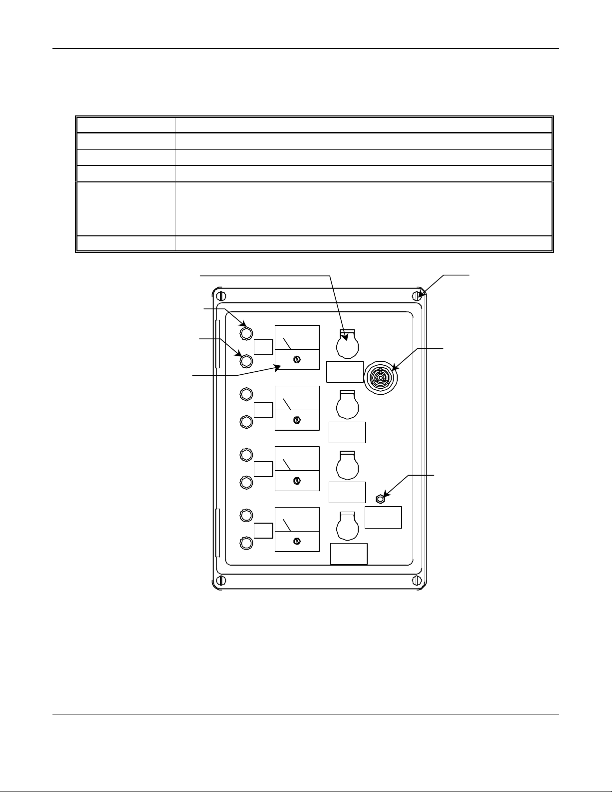
2.0 Features2.0 Features
See figure 1 for location of features
Feature Description
Meter A Oxygen (O2) concentration meter. The scale is marked in percent by volume O2.
Audio Alarm(Horn) Audio alarm (2900 Hz,95 dB at 2 ft.). The audio alarm is on when the unit is in alarm.
Gain Potentiometer
Visual Alarms
Relay Reset Button
LED, Red: Visual alarm (steady light). When this LED is on, power to the unit is on and
the unit is in high alarm.
LED, Green: When this is on, the unit is operating and is not in alarm. When this LED is
off, the unit is in alarm OR power to the unit has been interrupted.
Potentiometer
Alarm LED (red)
Power LED (green)
Meter
4 places
1
(Horn)
Gain
2
Gain
3
Button
Gain
Reset
4
Gain
Figure 1: ISA-40M Control Unit Exterior
2
Page 5
ISA-40M Oxygen Monitor ENMET Corporation
Mounting Holes
Transformer
Protective
Standoff cover
3.0 Installation3.0 Installation
WARNING: This equipment is not for use in hazardous combustible atmospheres as defined by the national
electrical code. Use in such atmospheres may result in property damage, injury or death
4 places
Fuse
TB3
TB5
Circuit Breakers
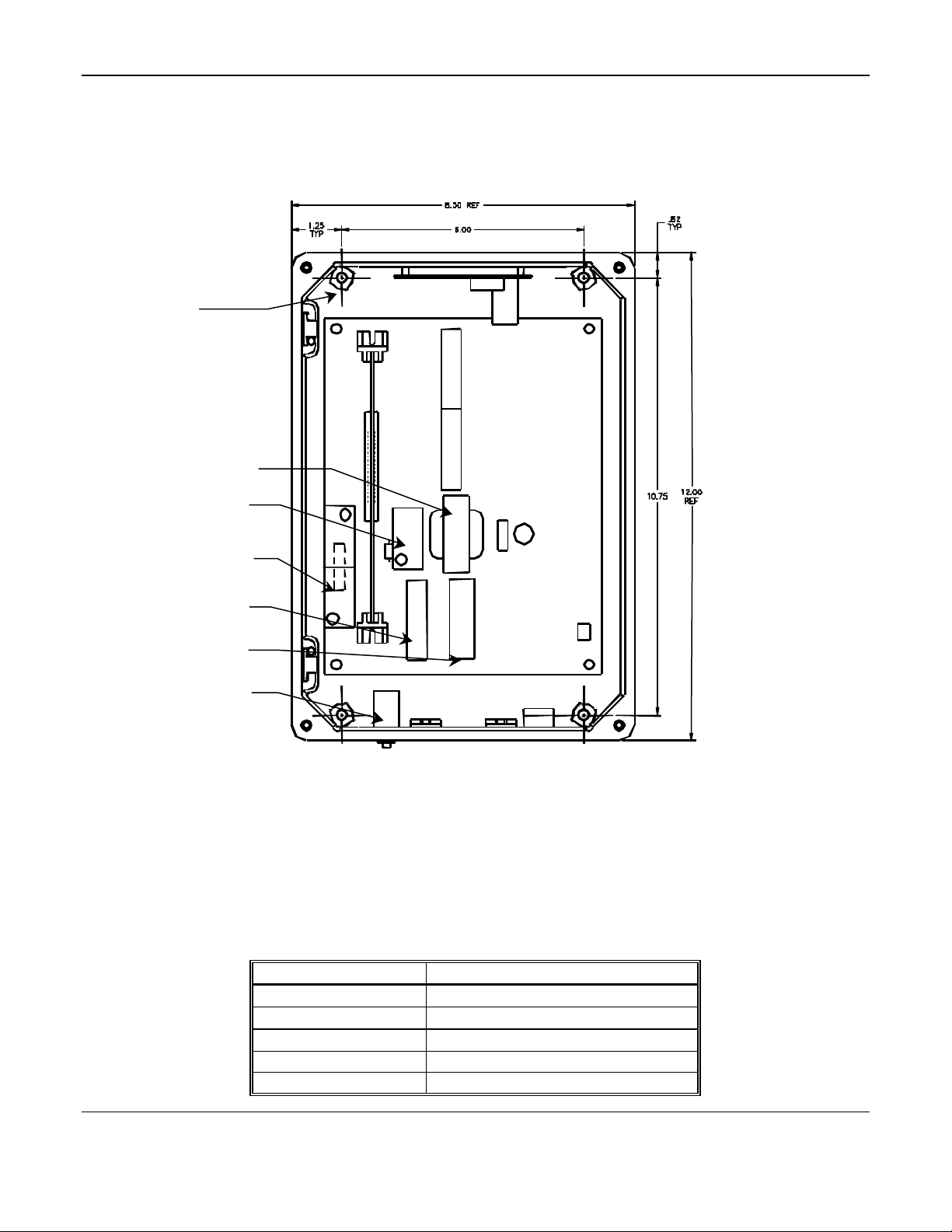
Figure 2: Mounting Dimensions
3.1 Control Unit Mounting and Power Hook-up
Use an appropriate fitting for conduit when supplying power to the unit.
1. Choose a suitable location for mounting the electronics control unit. See Figure 2 for mounting dimensions.
NOTE: All dimensions are given in inches.
2. Apply 110 VAC and/or 12 V DC power to the appropriate terminals on TB5 and TB3. Refer to the Wiring
Information table. Both 110 VAC and 12 V DC power can be applied together; the 12 VDC is standby power
source; DC current will flow only when the AC power is interrupted.
Table 1: Power Supply Wiring
Power supply ISA-40M Control Unit connection
110 VAC HOT TB5 HOT
110 VAC NEUTRAL TB5 NEUT
AC ground TB5 GND
12 VDC TB3-3 + V DC
DC ground TB3-1 or TB3-2
3
Page 6
ENMET Corporation ISA-40M Oxygen Monitor
Standoffs
Standoffs
Protective
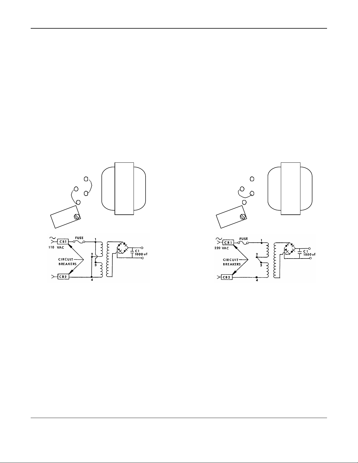
3.1.1 Converting to 220 Vac Power
The input of the transformer must be changed in order to accommodate 220 VAC power. This is accomplished by
changing the wiring between four standoffs located under a protective cover next to the transformer, shown in Figure 1.
The wiring configurations and the power supply schematics are shown in Figure 5.
To change power supply wiring of transformer form 110 VAC to 220 VAC, resolder the transformer standoff leads to the
appropriate configuration shown below. The materials required for this are a flathead screwdriver a soldering iron, 18
gauge (or larger) insulated wire and 60% tin/40% lead resin sore solder.
CAUTION: This procedure should be performed only by personnel with electrical repair experience.
1. Disconnect power from control unit.
2. Remove instrument circuit board to access transformer standoffs on motherboard.
3. Unscrew the cover-retaining screw and rotate protective standoff cover until standoffs are exposed.
4. Unsolder one lead at a time and then resolder to desired configuration (shown below).
5. Wipe up and remove excess solder.
6. Rotate protective cover over standoffs and tighten screws and replace circuit board.
110 VAC Wiring 220 VAC Wiring
Standoff Cover
(1,2,3,4)
2
4
1
Transformer
3
Standoff Cover
Protective
(1,2,3,4)
1
2
3
4
110 VAC Schematic 220 VAC Schematic
Transformer
4
Page 7

ISA-40M Oxygen Monitor ENMET Corporation
Remove Shoring
Bottom View O2 Sensor
O2 Cell Circuit Board
O2 Cell
ISA-40M Interior View
Clip or Spring
••Center Pin – Negative
••Outer Pin + Positive
w/cell installed on circuit side
Figure 3: Oxygen Cell Installation
Circuit Board
See note below
3.2 Oxygen Cell Installation
WARNING: The transducer cell must be installed and the oxygen monitor must be operational prior to using
cryogen with the MRI equipment magnet. If the monitor is not operational, there is a risk of
asphyxiation should a leak occur.
3.2.1 Oxygen Cell Installation Inside of Control Unit
The oxygen detection transducer cell is mounted inside the unit. The cell is packaged in a nitrogen filled plastic bag to
prevent depletion of useful life before installation. Do not open or puncture the bag before installation to insure best
performance of cell.
1. Remove 4 cover screws to open the control unit and remove screws to remove cell circuit board. See Figure 1 & 3.
2. Carefully remove the cell from the package.
3. Remove the metal shorting clip (or spring) from cell pins. See Figure 3.
4. Plug the cell into the component side of the cell circuit board; center pin to center hole. See Figure 3. Place the
board in the enclosure and replace the screws to secure the cell and circuit board.
5. Wait at least four hours for the cell to stabilize before setting the gain. The cell needs time to adjust to oxygen in
air, since it has been packaged in pure nitrogen.
6. The life expectancy of oxygen cells is about 14 months; warranty is six months. Remove the cell serial number
tag from the plastic bag, and stick it to the inside of the enclosure. In case of cell warranty problems, refer to this
serial number.
NOTE: If all channels are used with remote sensor assembly, remove the O2 Cell Circuit Board from the interior of the
ISA-40M. Reference Table 2 channel 1.
5
Page 8

ENMET Corporation ISA-40M Oxygen Monitor
Remove Shoring
Bottom View O2 Sensor
•• Outer Pin + Positive
O2 Cell
T
T
T
T
T
ISA-40M Interior View
3.2.2 Remote Sensor Assembly Wiring
See Figure 4 for location of terminal blocks.
Table 2: Remote Sensor Assembly Wiring
Channel Signal Control Unit Connection Sensor Connection
1 Oxygen Cell (–) TB1 – 1 O2 – TBS – 3
1 Oxygen Cell (+) TB1 – 1 O2 + TBS – 4
2 Oxygen Cell (–) TB1 – 2 O2 – TBS – 3
2 Oxygen Cell (+) TB1 – 2 O2 + TBS – 4
3 Oxygen Cell (–) TB2 – 3 O2 – TBS – 3
3 Oxygen Cell (+) TB2 – 3 O2 + TBS – 4
4 Oxygen Cell (–) TB2 – 4 O2 – TBS – 3
4 Oxygen Cell (+) TB2 – 4 O2 + TBS – 4
TB1
TB3
B
3
Clip or Spring
B
1
TB7
B
5
TB2
B
2
O2 Cell Circuit Board
w/cell installed on circuit side
B
4
TB4
TBS
•• Center Pin – Negative
Figure 4: Interior View of Sensor Assembly
Internal View: Remote Sensor Assembly
6
Page 9

ISA-40M Oxygen Monitor ENMET Corporation
O2 Cell
O2 Cell Port
Screws
Cover Screws
4 places
O2 Cell
Do Not over tighten
Circuit Board
Remote Sensor Assembly Top View Remote Sensor Cover (cut away)Side View
Figure 5: Remote Sensor Oxygen Cell Installation (Optional)
3.2.2 Oxygen Cell Installation for Remote Sensors
For some ISA-40M systems, single channel systems, and all multichannel systems, remote sensors are connected to
the control unit via wiring. To connect these assemblies to the control unit, see the Wiring Information table on the
previous pages. The transducer cells are each packaged in a nitrogen filled plastic bag to prevent depletion of useful
life before installation.
1. Open the control unit by removing the four screws on the display face corners. See Figure 1
2. Choose an appropriate location for mounting the oxygen sensor assembly. Remember that the sensor should be
situated so that oxygen deficient air reaches the sensor before such air affects persons in the area.
3. Mount the assembly. There are 4 holes in the assembly enclosure used for mounting.
4. Supply shielded sensor wiring from the control unit to the remote sensor.
• 2 insulated conductors, 18 gauge wire or larger.
•If cable is run through screen room walls, supply appropriate RF filters.
•Connect wire to terminals indicated in Table 2, remote sensor assembly wiring.
5. Remove screws in sensor assembly to remove oxygen cell mounting and cell circuit board. See Figure 5.
6. Carefully remove the cell from the package.
7. Remove the metal shorting clip(or spring) from the cell. See Figure 4.
8. Plug the cell into the component side of the cell circuit board in the oxygen sensor assembly; insert the center pin
of the cell into the center hole of the circuit board. Place the cell in position in the top of the assembly enclosure
and replace the screws to secure the cell in place.
CAUTION: Do not tighten screws too much; doing so can damage the components on the cell circuit board.
9. Wait at least 4 hours for the cell to stabilize; it must adjust to its new environment since it was packaged in pure
nitrogen.
10. Remove the cell serial number tag from the plastic oxygen cell package and retain. This is a warranty record (up
to six months from date of shipment from ENMET).
3.2.3 Oxygen Gain Adjustment
1. Four hours or more after installing the oxygen cell, use a screwdriver to turn the oxygen gain adjust, on the front
of the control unit enclosure. Turn it clockwise (increase) and counterclockwise (decrease) to see that the alarm
goes on and off as the meter needle passes the alarm level.
2. Expose each oxygen cell to fresh air for 5 minutes. Use cylinders of 20.9% oxygen in nitrogen if necessary to
guarantee oxygen content. See section 8.2.
3. After 5 minutes of clean air, adjust the oxygen gain so the meter reads 20.9%.
3.2.4 Circuit board Removal
The plug in circuit board assemblies cannot be plugged in backward because of a polarizing key in the edge connector.
It is not good practice to remove and replace the circuit card assemblies while power is applied to the unit.
7
Page 10

ENMET Corporation ISA-40M Oxygen Monitor
Normally
Common
Manual On/Off
T
3.3 Relay Outputs
Relay contacts can be used to activate other alarm signals or equipment away from the control unit enclosure when
there is an alarm condition and when the AC or DC power is interrupted. The contacts supplied are dry, with a rating of
2 Amp continuous, 5 Amp surge. Do not overload the ISA-40M power supply by connecting it through the relay
contacts to an inappropriate load. See Wiring Information Tables 3 & 4 and Sections 3.3.1 and 3.3.2 and the Figure 6
Utilizing Relay Contacts.
TB7 inside Control Unit;
Location of latching
relay contact terminals
TB7
TB3 inside Control Unit;
Location of non-latching
relay contact terminals
B
3
Internal view of ISA-40M
Figure 6: Utilizing the Relay contacts
Contact
Closed
Contact
Switch
Horn
Black
White
110 VAC
Power supply Outside
of Control Unit
Suggested wiring configuration for utilizing relay contacts
(manual on/off switch is suggested; user supplied component)
8
Page 11

ISA-40M Oxygen Monitor ENMET Corporation
3.3.1 Non-Latching Relays
There is one non-latching, single pole relay per channel. These relays furnish normally open, normally closed, and
common terminals, which are available on TB3 and TB4; refer to the motherboard drawing. These relays are fail-safe;
the power off position and the alarm position of the contacts are identical. Contact positions are given for the power
off, alarm condition.
Table 3: Non-Latching Relay Wiring
Non-powered, alarm positions are given
Channel Terminal Position Contact
1 TB3 – 1NC Normally closed
1 TB3 – 1NO Normally open
1 TB3 – 1COM Common
2 TB3 – 2NC Normally closed
2 TB3 – 2NO Normally open
2 TB3 – 2COM Common
3 TB4 – 3NC Normally closed
3 TB4 – 3NO Normally open
3 TB4 – 3COM Common
4 TB4 – 4NC Normally closed
4 TB4 – 4NO Normally open
4 TB4 – 4COM Common
3.3.2 Latching Relays
Latching relays are available on TB7, the terminal strip located on the auxiliary relay circuit assembly located on the
upper surface of the control unit enclosure. These relays, once triggered by an alarm condition, remain latched in the
alarm position until released by an operator, who activates the relay release pushbutton switch on the front of the
enclosure. This switch releases all latched relays together. These relays are not failsafe; the power off position of the
contacts is opposite from the latched alarm position. The contact positions given are for the power off, non-alarm
condition
Table 4: Latching Relay Wiring
Contacts are in non-powered, non-alarm position
Channel Terminal Position Contact
1 TB7 – 1 Normally closed
1 TB7 – 2 Normally open
1 TB7 – 3 Common
2 TB7 – 4 Normally closed
2 TB7 – 5 Normally open
2 TB7 – 6 Common
3 TB7 – 7 Normally closed
3 TB7 – 8 Normally open
3 TB7 – 9 Common
4 TB7 – 10 Normally closed
4 TB7 – 11 Normally open
4 TB7 – 12 Common
9
Page 12

ENMET Corporation ISA-40M Oxygen Monitor
4.0 Operation4.0 Operation
Install and power the unit as previously described in section 3.0 through 3.3.3.
The green LED on each channel is an indication that power is on and the unit is not in alarm. The red LED indicates
alarm, which is usually set at an oxygen content of 18.0%. The green LED goes out when the red LED goes on. If no
LEDs are on, power has been interrupted.
The meter, one per channel, gives a visual indication of oxygen content at the location of the sensor for that channel.
The meter scale reads from 16% to 26% oxygen by volume and is linear. The percentage of oxygen for fresh air,
20.9%, is the center point on the scale. The alarm point is typically 18.0% oxygen. Do not work in a space where the
indicated oxygen content is less than 16%. Follow your organization's policy and procedures in an alarm situation.
The audio alarm mounted on the front of the control unit enclosure activates when any one or more channels is in
alarm. In order to meet stringent safety requirements, the horn cannot be turned off during maintenance.
4.1 Rough Test
An oxygen alarm can be triggered to verify the alarm point by exhaling over the cell. If the ISA-40M includes a
remote sensor, two people are required to verify the alarm point, one at the sensor assembly and the other at the control
unit.
1. The individual at the sensor assembly inhales and holds his breath for 5 - 15 seconds.
2. Then he exhales slowly through the sintered screen in the cell enclosure.
3. The individual at the control unit observes that the alarm triggers at the alarm point, usually 18.0%.
4. A pressurized cylinder containing a mixture of 17.0% oxygen in nitrogen can be used with an appropriate
calibration assembly to trigger the alarm. See section 8.2.
4.2 Precautions Regarding the Cell
Do not expose the oxygen cell to temperatures below 32 °F (0°C) or above 130°F (55°C).
Never adjust the oxygen cell in an area where an oxygen deficiency may exist. Always adjust the oxygen cell in fresh
air. Use bottled air if necessary.
Avoid exposure to toxic gas environments.
4.3 Atmospheric Pressure Variations
The galvanic oxygen deficiency transducer cell current output is directly proportional to the partial pressure of the
oxygen in the atmosphere surrounding the cell. The partial pressure of oxygen is a function of the percent by volume
of oxygen in the air and the air pressure. Air pressure varies as natural weather systems move through the area,
causing changes in barometric pressure as well as oxygen content. The barometric pressure changes cause a relatively
small change in oxygen content indication; for example, if the gain is set to give an oxygen content meter indication of
20.9% oxygen when the barometric pressure is 29.9 inches of mercury, normal variations of barometric pressure cause
variations in meter readings of + or - 0.25%, from 20.65% oxygen by volume to 21.15% oxygen by vo lume. If the
gain is set during a normal high pressure weather cycle, the variation is 0.50% downscale; conversely, if the gain is set
during a normal low, the variation is upscale. This response to atmospheric pressure is not distressing when
understood. The variation of the alarm point by + or - 0.25% is not significant when the liberal safety factor between
the alarm point, usually 18.0%, and the point at which oxygen deficiency first emphatically affects human
performance, approximately 16.0%, is taken into consideration
4.4 Temperature Variations
The cell output is temperature dependent; consequently, the cell is temperature compensated by means of a thermistor
resistor network on the circuit board in the sensor assembly. Significant changes in temperature cause erratic initial
readings, as the cell and thermistor do not track due to the difference in their locations and thermal masses. This
phenomenon is significant in portable instruments, but usually does not affect the operation of permanent systems.
10
Page 13

ISA-40M Oxygen Monitor ENMET Corporation
Channel 3 & 4
Channel 1 & 2
5.0 Maintenance5.0 Maintenance
5.1 Cell Aging
The output of the cell decreases with cell usage. The change is very small during the operational life of the cell, 12-14
months, and is compensated by changing the gain to cause the meter reading to be 20.9% in fresh air. Gain reset and
rough test (Sections 3.2.3 and 4.1) should be accomplished every 4 – 6 weeks.
NOTE: When adjusting the gain, if the air at the sensor locations is suspected to be depleted in oxygen, bottled air and
a calibrator should be used; see section 8.2.
5.2 Cell End-of-Life
When the electrodes in the transducer cell are finally depleted, the cell output terminates rather quickly. The first
indication that this is occurring is generally an inability to adjust the gain to yield a 20.9% reading in fresh air. Then
the cell output decreases until the channel is constantly in alarm. To install a new cell, follow the procedures given in
sections 3.2.1 and 3.2.2. If installing a cell in a remote sensor assembly with audio alarm, disconnect the ground side
of the sensor assembly audio alarm during this process to avoid spurious alarms while changing the cell; reconnect it
when done.
5.3 Circuit Alignment
Each ISA-40M system is aligned at the factory; however, due to prolonged use, oxygen cell replacement and assorted
other circumstances, it may become necessary to realign the circuitry. If the unit is in constant alarm, the oxygen
micro fuel cell has probably expired. Proceed to the cell replacement section 5.2, then come back to this one. The
procedure for realignment is not difficult, but be aware that any deviation from the procedure described below voids
the warranty. If you have any doubts about the procedure, contact ENMET personnel.
The only tools necessary are a digital voltmeter and a small screwdriver. This procedure is given for an S-2 oxygen
cell, ENMET P/N 67013-008 as furnished as a replacement cell; this cell has a grey label. Refer to Figure 7 for test
point and potentiometer locations.
Circuit Board
Circuit Board
Edge view of Circuit Board Interior view of 4 channel ISA-40M
Figure 7: Location of Circuit Boards, Test points and Potentiometers
11
Page 14

ENMET Corporation ISA-40M Oxygen Monitor
1. Null adjust:
a) Disconnect the oxygen cell from the circuit by disconnecting leads at TB1 or TB2 as shown below:
Channel Disconnect Terminal Positions
1 TB1 – 1 O2 (+) and TB1 – 1 O2 (–)
2 TB1 – 2 O2 (+) and TB1 – 2 O2 (–)
3 TB2 – 3 O2 (+) and TB2 – 3 O2 (–)
4 TB2 – 4 O2 (+) and TB2 – 4 O2 (–)
b) Check the null voltage for the channel. Connect the voltmeter leads to the appropriate test points, shown below:
Channel Test points On Circuit Board
1 TP101 (–), TP102 (+) For channel(s) 1 (and 2)
2 TP201 (–), TP202 (+) For channels 1 and 2
3 TP101 (–), TP102 (+) For channel(s) 3 (and 4)
4 TP201 (–), TP202 (+) For channels 3 and 4
c) Adjust the appropriate null adjust potentiometer, shown below, so the voltage between the points is 0.00 VDC:
Channel Potentiometer On Circuit Board
1 R108 For channel(s) 1 (and 2)
2 R208 For channels 1 and 2
3 R108 For channel(s) 3 (and 4)
4 R208 For channels 3 and 4
2. Low Level Set Adjust:
a) Reconnect the oxygen cell by reconnecting the leads removed in step 2 a).
b) Make sure the oxygen cell is properly connected by measuring the voltage between the cell leads; this voltage
must be between 0.043 and 0.09 VDC.
c) Measure the Low Level Set voltage for the channel by connecting the voltmeter leads to the appropriate test
points, shown below:
Channel Test point On Circuit Board
1 TP101 (–), TP103 (+) For channel(s) 1 (and 2)
2 TP201 (–), TP203 (+) For channels 1 and 2
3 TP101 (–), TP103 (+) For channel(s) 3 (and 4)
4 TP201 (–), TP203 (+) For channels 3 and 4
d) Adjust appropriate low level set potentiometer, R112 or R212, so the voltage between the test points is 1.03 V DC.
Channel Potentiometer On Circuit Board
1 R112 For channel(s) 1 (and 2)
2 R212 For channels 1 and 2
3 R112 For channel(s) 3 (and 4)
4 R212 For channels 3 and 4
3. Full Scale Adjustment:
a) Place voltmeter leads at the appropriate positions, shown below, to adjust the full scale voltage:
Channel Test point On Circuit Board
1 TP101 (–), TP102 (+) For channel(s) 1 (and 2)
2 TP201 (–), TP202 (+) For channels 1 and 2
3 TP101 (–), TP102 (+) For channel(s) 3 (and 4)
4 TP201 (–), TP202 (+) For channels 3 and 4
b) Adjust the appropriate oxygen gain potentiometer on the front panel of the control unit so the voltage between
the test points is 1.55 V DC.
12
Page 15

ISA-40M Oxygen Monitor ENMET Corporation
c) Adjust the appropriate meter gain potentiometer, shown below, so the channel's meter reads full scale (26%
oxygen on most meters). Adjust this pot. Counterclockwise to increase, clockwise to decrease meter reading.
Channel Potentiometer On Circuit Board
1 R110 For channel(s) 1 (and 2)
2 R210 For channels 1 and 2
3 R110 For channel(s) 3 (and 4)
4 R210 For channels 3 and 4
d) Remove the voltmeter leads from the test points.
4. Alarm Set Adjust:
a) Adjust the oxygen gain potentiometer for the particular channel until the meter reads at the appropriate alarm
point (usually 18.0%).
b) Adjust the appropriate alarm point adjust potentiometer, indicated below, counterclockwise until the oxygen
circuit just barely goes into alarm. The red oxygen deficiency LED should just activate as you adjust this
potentiometer. If LED is on before the potentiometer adjustment, adjust this potentiometer clockwise until the
LED is off, then readjust counterclockwise until the LED just barely activates:
Channel Potentiometer On Circuit Board
1 R116 For channel(s) 1 (and 2)
2 R216 For channels 1 and 2
3 R116 For channel(s) 3 (and 4)
4 R216 For channels 3 and 4
c) Using the oxygen gain potentiometer on the front of the control unit for the channel you are working on, adjust
the channel's oxygen meter up so that the channel comes out of alarm. Then adjust down again slowly until to
verify that the unit goes into alarm.
d) Expose the channel's oxygen cell to clean, fresh air for 5 minutes. Using the oxygen gain potentiometer, adjust
the meter to read 20.9%.
IMPORTANT: The oxygen sensor MUST be in clean, fresh air for this adjustment. If there is any possibility
that oxygen deficient air is near the sensor, supply bottled 20.9% oxygen to the sensor for a couple of minutes,
then adjust gain.
e) If possible, exhale all your breath over the oxygen cell. The meter reading should drop and the oxygen alarm
should come on at the predetermined alarm point (usually 18.0% oxygen by volume).
f) If the oxygen alarm does not come on at this point, repeat the entire procedure checking terminal connections,
test points, and voltage settings very carefully. If it still does not alarm, contact your local authorized ENMET
service center.
5. The oxygen circuit alignment is now complete.
5.4 Circuit Breakers / Fuse
ISA-40M instruments above serial number 2568 are equipped with two circuit breakers and a fuse in the AC power
supply wiring. The circuit breakers are rated at 1 amp, and the fuse is rated at 50 milliamps (slow blow).
When the fuse or a circuit breaker opens the circuit, the power supply to the ISA-40M is interrupted. All LEDs on the
front of the instrument are off. First, check to see if one or both circuit breakers have released their reset button. If so,
press in the reset button. If not, visually check the fuse for a broken element , then test the fuse electrically for
continuity. If the fuse element is broken (visual indication) or cracked (electrical indication), replace it with the same
fuse (see section 7.1 for part number). If, after resetting a circuit breaker or replacing the fuse, the same component
opens the circuit again within a short period of time, do not attempt to reset or replace the component again; have the
instrument and power supply inspected to determine the source of the overload.
CAUTION: The fuse for the ISA-40M is a "slow blow" fuse. If this fuse requires replacement, the exact replacement is
required (see section 7.1 for part number). Any other type voids the electrical certification. Note also that if the
replacement fuse is not a "slow blow" fuse, the replacement fuse will blow as soon as the instrument is supplied
with power.
13
Page 16

ENMET Corporation ISA-40M Oxygen Monitor
6.0 ISA-40M Specifications6.0 ISA-40M Specifications
Control Unit Specifications
Power 110 VAC (or 220 VAC if transformer standouts are reconfigured),
50/60 Hz, and/or 12 V DC, 20 watts max. (5 watts per channel)
Alarm Horn and red LEDs on Control Unit.
Sensor Lifetime Approximately 14 months.
Warranted for 6 months from date of shipment.
Electronics Low power, all solid state, utilizing integrated circuits.
Dimensions 12" high x 8" wide x 7" deep
Weight 20 lbs.
Enclosure NEMA-4X Fiberglass
Oxygen Cell Specifications
Application General. Intermediate life and response time.
Response Time
Output
Operating Temp. Range
ENMET Warranty 6 months form shipment
Size
Weight 26 grams
Expected Life Up to 14 months in air
NOTE: All specifications stated in this manual may change without notice.
90% in 15 seconds, at 25 °C (typical)
Nominal (in air at 25°C) 175 ± 5uA
At 0% Oxygen less than 2.0uA
Linearity error (0 – 100% Oxygen) less than 0.5%
32°F to 125°F
1.25″ diameter by 0.80″ long
7.0 Service Information7.0 Service Information
7.1 Replacement Part Numbers
A full set of replacement part numbers and prices are a part of the documentation which accompanied the order. A
partial list of the most likely parts needed to maintain the equipment is as follows:
ENMET Part Number Description
67013-008
03296-209 24 liter, 240 psi cylinder of 20.9% oxygen in nitrogen
03296-170 24 liter, 240 psi cylinder of 17% oxygen in nitrogen
63001-002 14 VDC lamp
03600-002 Assembly, Calibrator
04537-005 Circuit board, one channel
04537-007 Circuit board, two channel
64002-050 Fuse, 0.05 Amp, 5x20 slow blow
66017-009 Sensor cable, specify length
Oxygen Cell, S2, that has a grey label;
The p/n is for the packaged cell as furnished for a replacement
14
Page 17

ISA-40M Oxygen Monitor ENMET Corporation
7.2 Return for Repair
ENMET instruments may be returned to the factory or any one of our Field Service Centers for regular repair service
or calibration. The ENMET Repair Department and Field Service Centers also perform warranty service work.
There is a Repair Return Form on the last page of this manual. This form can be copied or used as needed.
When returning an instrument to the factory or service center for service, paperwork must be included which contains
the following information:
q A purchase order number or reference number.
q A contact name with return address, telephone and fax numbers
q Specific instructions regarding desired service or description of the problems being encountered.
q Date of original purchase and copy of packing slip or invoice for warranty consideration.
q If a price estimate is required, please note it accordingly and be sure to include a fax number.
Providing the above information assists in the expedient repair and return of your unit.
Failure to provide this information can result in processing delays.
ENMET charges a one hour minimum billing for all approved repairs with additional time billed to the closest tenth of
an hour. All instruments sent to ENMET are subject to a minimum $30 evaluation fee, even if returned unrepaired.
Unclaimed instruments that ENMET has received without appropriate paperwork or attempts to advise repair costs
that have been unanswered, after a period of 60 days, may be disposed of or returned unrepaired COD with the
evaluation fee.
Service centers may have different rates or terms. Be sure to contact them for this information.
Repaired instruments are returned by UPS/RPS surface and are not insured unless
otherwise specified. If expedited shipping methods or insurance is required , it must be
stated in your paperwork.
Note: Warranty of customer installed components.
If a component is purchased and installed in the field, and fails within the warranty term, it can be returned to
ENMET and will be replaced, free of charge, per ENMET’s returned goods procedure.
If the entire instrument is returned to ENMET Corporation with the defective item installed, the item will be
replaced at no cost, but the instrument will be subject to labor charges at half of the standard rate.
15
Page 18

ENMET Corporation ISA-40M Oxygen Monitor
8.0 WARRANTY8.0 WARRANTY
ENMET warrants new instruments to be free from defects in workmanship and material under normal use for a period
of one year from date of shipment from ENMET. The warranty covers both parts and labor excluding instrument
calibration and expendable parts such as calibration gas, filters, batteries, etc... Equipment believed to be defective
should be returned to ENMET within the warranty period (transportation prepaid) for inspection. If the evaluation by
ENMET confirms that the product is defective, it will be repaired or replaced at no charge, within the stated
limitations, and returned prepaid to any location in the United States by the most economical means, e.g. Surface
UPS/RPS. If an expedient means of transportation is requested during the warranty period, the customer is responsible
for the difference between the most economical means and the expedient mode. ENMET shall not be liable for any
loss or damage caused by the improper use of the product. The purchaser indemnifies and saves harmless the
company with respect to any loss or damages that may arise through the use by the purchaser or others of this
equipment.
This warranty is expressly given in lieu of all other warranties, either expressed or implied, including that of
merchantability, and all other obligations or liabilities of ENMET which may arise in connection with this equipment.
ENMET neither assumes nor authorizes any representative or other person to assume for it any obligation or liability
other than that which is set forth herein.
NOTE: When returning an instrument to the factory for service:
§ Be sure to include paperwork.
§ A purchase order, return address and telephone number will assist in the expedient repair and return of your unit.
§ Include any specific instructions.
§ For warranty service, include date of purchase
§ If you require an estimate, please contact ENMET Corporation.
16
 Loading...