

Page 1

ENMET Corporation
PO Box 979
Ann Arbor, MI 48106-0979
Manual Part Number
80003-133
MCN-339, 10/04/05
EN / SDS
Electrochemical
Sensor/Transmitter
Installation Manual
Page 2

Table of Contents
INTRODUCTION ................................................................................................................................................................................... 1
1.0 UPON RECEIPT ............................................................................................................................................................................... 1
1.1 U
NPACK
............................................................................................................................................................................................ 1
1.2 C
HECK ORDER
1.3 S
ERIAL NUMBERS
2.0 MOUNTING AND WIRING ............................................................................................................................................................ 2
2.1 I
NSTALLATION OF SENSOR/TRANSMITTER
3.0 INITIAL CALIBRATION ................................................................................................................................................................ 4
4.0 STANDARD RANGES, CALIBRATION GASES, VOLTAGE READINGS AT CALIBRATION POINTS AND
APPROXIMATE TIMES TO SENSOR STABILIZATION ................................................................................................................. 5
5.0 ENMET PART NUMBERS............................................................................................................................................................... 6
5.1 R
EPLACEMENT SENSORS
5.2 C
ALIBRATION GASES
Calibration Gases and Accessories ................................................................................................................................................... 6
6.0 WARRANTY ..................................................................................................................................................................................... 7
APPENDIX A: INTERFERENCE TABLE ........................................................................................................................................... 8
.................................................................................................................................................................................. 1
............................................................................................................................................................................. 1
........................................................................................................................................ 3
................................................................................................................................................................... 6
........................................................................................................................................................................ 6
List of Illustrations
F
IGURE 1: SENSOR/TRANSMITTER, EXTERNAL FRONT VIEW
F
IGURE 1A: SENSOR/TRANSMITTER
F
IGURE 2: SENSOR/TRANSMITTER 4 – 20MA IN
F
IGURE 2A: SENSOR/TRANSMITTER 4 – 20MA IN
F
IGURE 3: CALIBRATION SETUP, 4 – 20MA SENSOR/TRANSMITTER
T
ABLE 1: ELECTROCHEMICAL SENSORS
10015-1105, E
..................................................................................................................................................... 5
XTERNAL FRONT VIEW
NEMA-4 P
NEMA-4 P
...................................................................................................................... 2
................................................................................................ 2
ACKAGE, INTERNAL VIEW
ACKAGE, INTERNAL VIEW
........................................................................................................... 4
.............................................................................. 3
............................................................................ 3
Page 3

Sensor/Transmitter, Toxic Gas & Oxygen ENMET Corporation
Introduction
The ENMET toxic and oxygen sensor/transmitters (S/T) model EN series are two wire 4-20mA devices. The housing is a
sealed NEMA-4 aluminum enclosure. The sensor/transmitter operates on 15 to 36VDC and can be connected to any control that
utilizes a 4-20mA output. When connecting the sensor/transmitter to a control consult installation instructions and manuals for
that control or contact ENMET or your ENMET distributor.
N
OTE
: All specifications stated in this manual may change without notice.
1.0 Upon Receipt
1.1 Unpack
Unpack the sensor/transmitter (S/T) and examine it for shipping damage. If such damage is observed, notify both ENMET
customer service personnel and the commercial carrier involved immediately.
Regarding Damaged Shipments
N
OTE
: It is your responsibility to follow these instructions. If they are not followed, the carrier will not honor
any claims for damage.
This shipment was carefully inspected, verified and properly packaged at our company and delivered to the carrier in good
condition.
When it was picked up by the carrier at ENMET, it legally became your company’s property.
If your shipment arrives damaged:
• Keep the items, packing material, and carton “As Is.” Within 5 days of receipt, notify the carrier’s local office and
request immediate inspection of the carton and the contents.
• After the inspection and after you have received written acknowledgment of the damage from the carrier, contact
ENMET Customer Service for return authorization and further instructions. Have your Purchase Order and Sales Order
numbers available.
ENMET either repairs or replaces damaged equipment and invoices the carrier to the extent of the liability coverage,
usually $100.00. Repair or replacement charges above that value are your company’s responsibility.
The shipping company may offer optional insurance coverage. ENMET only insures shipments with the shipping
company when asked to do so in writing by our customer. If you need your shipments insured, please forward a written
request to ENMET Customer Service.
Regarding Shortages
If there are any shortages or questions regarding this shipment, please notify ENMET Customer Service within 5 days of
receipt at the following address:
ENMET Corporation
680 Fairfield Court
Ann Arbor, MI 48108
734-761-1270 734-761-3220 Fax
1.2 Check Order
Check, against the purchase order. Verify that the S/T is received as ordered. Each S/T is labeled with its target gas. If there
are accessories on the order, ascertain that they are present. Check the contents of calibration kits. Notify ENMET customer
service personnel of any discrepancy immediately.
1.3 Serial Numbers
Each sensor/transmitter is serialized. These numbers are on tags on the equipment and are on record in an ENMET database.
1
Page 4
Sensor/Transmitter, Toxic Gas & Oxygen ENMET Corporation
2.0 Mounting and Wiring
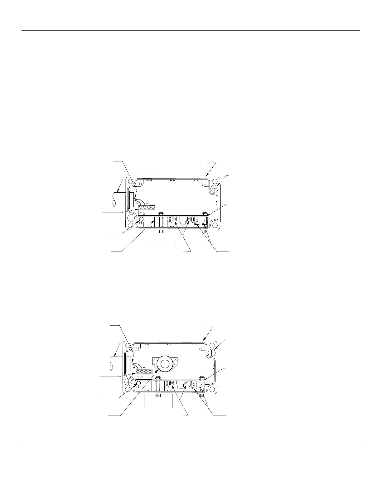
Each sensor/transmitter circuit and sensor are in a NEMA-4 aluminum enclosure, which has a combination liquid and RFI O-ring
in the cover. When used with an appropriate liquid tight conduit fitting, the enclosure is sealed to the environment. The interior
of a typical S/T is shown in Figure 2.
When determining location of S/T here are 3 main factors to consider.
♦ Density of gas to be detected: high for gases lighter than air and low for gases heavier than air
♦ Leak point: determination of the probable source of a leak
♦ In the flow of air in ventilated rooms.
Mount the sensor/transmitter to an appropriate stable vertical surface with the sensor facing downward.
C
AUTION
: Since the sensor/transmitter detects gas only at the sensor location, pay attention to the possible sources of gas, the
density of the gas, locations where the gas may be confined and locations where the gas may damage or injure property or
personnel, when choosing locations of sensor/transmitters.
Mount the sensor/transmitter using the two mounting holes in the corners of the enclosure. For maximum RFI protection the
enclosure should be grounded to earth ground, either by means of the mounting screws, a conductive conduit, or a wire
connected to earth ground.
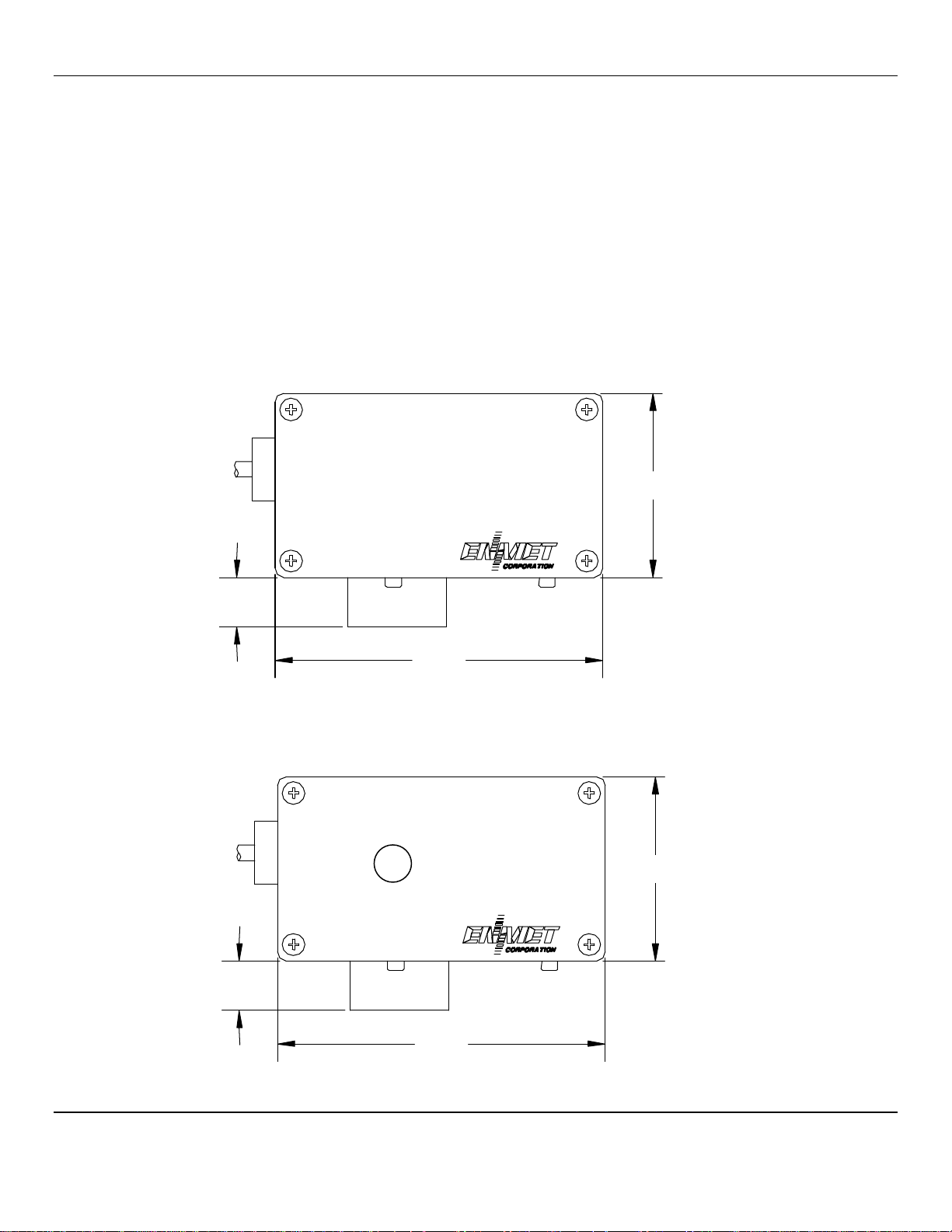
2.55”
0.68”
4.55”
Figure 1: Sensor/Transmitter, External Front View
2.55”
0.68”
4.55”
Figure 1a: Sensor/Transmitter 10015-1105, External Front View
2
Page 5
Sensor/Transmitter, Toxic Gas & Oxygen ENMET Corporation
•
•
•
2.1 Installation of Sensor/Transmitter
1. J Remove the cover, and mount the S/T in a location appropriate for the application. Use the enclosure mounting holes as
shown in Figure 2. The sensor faces down. Pay particular attention to the source and density of the target gas in choosing
the S/T location.
2. J The hole in the left side wall of the S/T enclosure is sized to accommodate a liquid tight conduit fitting. Run conduit from
the S/T to the control. If intrinsically safe barriers are supplied, because the S/Ts are in a classified location, follow the
applicable electrical code provisions for intrinsically safe wiring. Run two wires through conduit. If the conduit is
metallic and does not contain other wiring likely to generate interference signals, unshielded insulated wires can be used.
Otherwise, use two wire shielded cable and ground the shield to the S/T enclosure. The S/T enclosure should be grounded
to earth ground for maximum RFI protection.
3. J Connect the plus wire to TB1-1 and the minus wire to TB1-2 on the S/T circuit board, as shown in Figure 2.
C
AUTION
: Before connecting S/T to C
ONTROL
remove the power source to C
ONTROL
. Failure to do so may cause damage to
sensitive components.
4 – 20mA,
12 – 28VDC
Liquid Tight
Conduit
Fitting
NEMA-4 Aluminum Enclosure
shown without cover
Mounting Hole
2 places
TB1
Circuit Board
Red LED
Sensor
Test Points
POTs: Gain and Zero
• Note: No Zero pot in oxygen S/T
Figure 2: Sensor/Transmitter 4 – 20mA in NEMA-4 Package, Internal View
4 – 20mA,
12 – 28VDC
Liquid Tight
Conduit
Fitting
NEMA-4 Aluminum Enclosure
shown without cover
Mounting Hole
2 places
TB1
Circuit Board
Red LED
Sensor
Test Points
POTs: Gain and Zero
Note: No Zero pot in oxygen S/T
Figure 2a: Sensor/Transmitter 4 – 20mA in NEMA-4 Package, Internal View
3
Page 6

Sensor/Transmitter, Toxic Gas & Oxygen ENMET Corporation
•
Red LED
POT’s: Gain Zero
•
Note: No Zero pot in Oxygen S/T
3.0 Initial Calibration
The S/T is pre-calibrated at the factory before shipment, and initial field calibration should result in only fine-tuning of the
circuit. In all cases allow the S/Ts to stabilize; this may take as much as an hour depending on the type of sensor and the length
of time it has been inactive. The S/T output is monitored with a voltmeter by means of the test points on the S/T circuit board
see figure 2; the transfer function is:
4mA = 100 mv 20ma = 500 mv
tolerance: + or - 5 mv
On Toxic sensor/transmitters the LED also indicates current flow; it is dim at 4mA and bright at 20mA. When the sensor is
stable and is in air uncontaminated by the target gas, adjust zero to
4mA = 100mv with the zero potentiometer, see Figure 2.
If a calibration kit was purchased and field calibration is desired, apply the span gas to the sensor. The regulator of the
calibration adapter screws into the top of the gas cylinder; the cup of the adapter slips into the hub of the sensor/transmitter, see
Figure 3. Allow the gas to flow for the time indicated in Table 1 in Section 4.0 and observe that the reading is stable. Adjust
the gain potentiometer on the S/T board to the appropriate output while monitoring the voltmeter. The voltage readings for
standard ranges are given in Table 1 in Section 4.0.
If the sensor/transmitter has a non-standard range, and/or a non-standard calibration gas is used do a linear interpolation to
determine the voltage reading at the calibration point.
Example: toxic, if the maximum range is 100ppm = 20ma, and a 25ppm gas is used, adjust the gain potentiometer so that the
display reads 25 or the voltmeter reads 200mv.
(25/100)(500-100) + 100 = 200mv
Example: oxygen, the maximum range is 30.0% = 20mA, and a 20.9 gas is used, adjust the gain potentiometer so the display
reads 20.9 or the voltmeter reads 379mv.
Remove the span gas and replace the S/T cover.
Test Points
TB1
Red LED
CALIBRATION
ADAPTER
Figure 3: Calibration Setup, 4 – 20mA Sensor/Transmitter
(20.9/30)(500-100) + 100 = 379mv
Test Points
TB1
CALIBRATION
ADAPTER
Circuit Board
POTs: Gain and Zero
Note: No Zero pot in oxygen S/T
REGULATOR
GAS CYLNDER
4
Page 7

Sensor/Transmitter, Toxic Gas & Oxygen ENMET Corporation
4.0
Standard Ranges, Calibration Gases, Voltage Readings at Calibration Points and
Approximate Times to Sensor Stabilization
Table 1: Electrochemical Sensors
Gas
Ammonia NH3 0 – 100 25ppm NH3 200 4 03218-025
Arsine (2) AsH3 0 – 0.5 0.5ppm PH3 0.375ppmAsH3 400 3 03202-005
Boron Trichloride BCl3 0 – 30 10ppm HCl 10ppm BCl3 233 3 03202-010
Carbon Monoxide CO 0 – 100 50ppm CO 300 2 03219-050
Chlorine (2) Cl2 0 – 10 5ppm Cl2 300 4 03231-005
Chlorine Dioxide ClO2 0 – 1.0 0.3ppm ClO2** 220 4 **
Dichlorosilane SiH2Cl2 0 – 30 10ppm HCl 3ppm SiH2Cl2 140 3 03202-010
Ethylene Oxide C2H4O 0 – 30 5ppm C2H4O 167 3 03232-005
Fluorine (2) F2 0 – 10 3ppm Cl2 7.5ppm F2 400 3 03231-003
Hydrogen H2 0 – 1000 800ppm H2 420 3 03227-800
Hydrogen Bromide HBr 0 – 30 5ppm HCl 25ppm HBr 433 3 03202-005
Hydrogen Chloride (2) HCl 0 – 30 10ppm HCl 233 3 03202-010
Hydrogen Cyanide HCN 0 – 30 10ppm HCN 233 2 03203-010
Hydrogen Fluoride (1) HF 0 – 10 5ppm Cl2 3ppm HF 220 4 03202-005
Hydrogen Sulfide H2S 0 – 100 20ppm H2S 180 2 03214-020
Nitrogen Dioxide NO2 0 – 30 5ppm NO2 167 2 03233-005
Nitric Oxide NO 0 – 100 25ppm NO 200 1.5 03234-025
Oxygen O2 0 – 30 % 20.9% O2 379 2 03296-209
Ozone (1) O3 0 – 1.0 0.3ppm O3** 220 3 **
Phosgene (1) COCl2 0 – 1.0
Phosphine (2) PH3 0 – 1.0 0.5ppm PH3 300 1.5 03205-005
Silane SiH4 0 – 30 5 ppm SiH4 167 2 03306-005
Silicon Tetrachloride SiCl4 0 – 30 5ppm HCl 25ppm SiCl4 433 3 03202-005
Sulfur Dioxide SO2 0 – 30 10ppm SO2 233 1.5 03215-010
N
OTE
: All specifications stated in this manual may change without notice.
(1) Require use of Sample Draw System.
(2) Recommended use of Sample Draw System, for enhanced sensitivity and speed of response.
Symbol
Range*
(ppm) Calibration Gas
0.66ppm COCl2**
Correlation
Reading
(mV)
364 4 **
Stabilize
(min.)
ENMET Gas
Part Number
*0 = 4mA = 100mV, upper point = 20mA = 500 mV
**Gas not available in cylinders, a gas generator must be used
N
OTE
: If a non-standard range and/or a non-standard calibration gas are used, utilize the equations in Section 3.0 to determine
voltage readings.
5
Page 8

Sensor/Transmitter, Toxic Gas & Oxygen ENMET Corporation
5.0 ENMET Part Numbers
5.1 Replacement Sensors
Sensor Gas Type ENMET Part Number
Chlorine 67020-0100
Hydrogen Sulfide 67020-0201
Hydrogen Cyanide 67020-0300
Hydrogen Chloride 67020-0400
Sulfur Dioxide (with H2S filter) 67016-0500
Phosgene 67020-0600
Hydrogen Fluoride 67020-0700
Ozone 67020-0803
Oxygen 67016-1106
Oxygen MRI 67013-008
Carbon Monoxide: For S/T P/N ending in -1203 67020-1201
Carbon Monoxide: For S/T P/N ending in -1207 67016-1200
Fluorine 67020-1400
Hydrogen 67020-1500
Nitrogen Dioxide 67020-1700
Nitric Oxide 67020-1750
Ammonia 67020-2400
Arsine 67020-4001
Phosphine 67020-4002
Silane 67020-4003
5.2 Calibration Gases
Calibration Gases and Accessories
Calibration gas part numbers are given in Table 1, in Section 4.0.
Adapter Style ENMET Part Number
For Ammonia, Nitric oxide, Hydrogen chloride, Hydrogen cyanide 02506-001
For Chlorine and Hydrogen sulfide 02506-002
For Sulfur dioxide and Nitrogen dioxide 02506-003
For Oxygen and Carbon monoxide 02506-000
Calibration Cap (required with all adapters) 03620-010
Calibration Cap Reactive Gases
Calibration Cap Catalytic Sensor 03620-012
Calibration Regulator w/cal cup Oxygen, MRI 03600-002
Ozone generator, 0.5 to 5.0 ppm at 1.0 lpm 04055-0800
Contact ENMET
6
Page 9

Sensor/Transmitter, Toxic Gas & Oxygen ENMET Corporation
6.0 Warranty
ENMET warrants new instruments to be free from defects in workmanship and material under normal use for a period of one
year from date of shipment from ENMET. The warranty covers both parts and labor excluding instrument calibration and
expendable parts such as calibration gas, filters, batteries, etc... Equipment believed to be defective should be returned to
ENMET within the warranty period (transportation prepaid) for inspection. If the evaluation by ENMET confirms that the
product is defective, it will be repaired or replaced at no charge, within the stated limitations, and returned prepaid to any
location in the United States by the most economical means, e.g. Surface UPS/FedEx Ground. If an expedient means of
transportation is requested during the warranty period, the customer is responsible for the difference between the most
economical means and the expedient mode. ENMET shall not be liable for any loss or damage caused by the improper use of
the product. The purchaser indemnifies and saves harmless the company with respect to any loss or damages that may arise
through the use by the purchaser or others of this equipment.
This warranty is expressly given in lieu of all other warranties, either expressed or implied, including that of merchantability,
and all other obligations or liabilities of ENMET which may arise in connection with this equipment. ENMET neither assumes
nor authorizes any representative or other person to assume for it any obligation or liability other than that which is set forth
herein.
N
OTE:
When returning an instrument to the factory for service:
Be sure to include paperwork.
A purchase order, return address and telephone number will assist in the expedient repair and return of your unit.
Include any specific instructions.
For warranty service, include date of purchase
If you require an estimate, please contact ENMET Corporation.
There is a Repair Return Form on the last pages of this manual. This form can be copied or used as needed.
Manual Part Number
80003-133
July 2004
MCN-339, 10/04/05
7
Page 10

Sensor/Transmitter, Toxic Gas & Oxygen ENMET Corporation
Interferant
Interferant Concentration
Instrument Reading
ethanol
1000
1
isopropanol
450 1
hydrogen sulfide
14 10
methanol
1200
3
hydrogen
1000
80
carbon monoxide
300 100
sulfur dioxide
25 -21
nitrogen dioxide
50 25
hydrogen cyanide
10 -18
Interferant Gas/Vapor
Concentration in ppm
chlorine
5
unsaturated hc (ethylene)
1.0 %
saturated hydrocarbons
abundant
Interferant
Interferant Concentration
Instrument Reading
hydrogen
1000
450
nitric oxide
100 25
Interferant Gas/Vapor
Concentration in ppm
ammonia
100
chlorine
5
hydrogen cyanide
10
ethylene
2.0 % *
carbon dioxide
5,000
methane
10,000
sulfur dioxide
10 *
hydrogen sulfide
10 *
nitrogen dioxide
10 *
isopropanol
1,025 *
gasoline vapor
saturated *
Appendix A: Interference Table
For Selected Sensors
Ammonia (3E-100 sensor)
The following gases cause a reading:
Gas/Vapor
The following gases or vapors have been tested and do not cause a reading:
in ppm
Carbon Monoxide (3E sensor)
The following gases cause a reading:
Gas/Vapor
The following gases or vapors have been tested and do not cause a reading:
in ppm
in ppm
in ppm
* With onboard filter; continuous high level exposure may reduce the filter efficiency
8
Page 11

Sensor/Transmitter, Toxic Gas & Oxygen ENMET Corporation
Interferant
Interferant Concentration
Instrument Reading
hydrogen sulfide
10 -0.3
sulfur dioxide
5 -1.2
nitrogen
dioxide
5
0.1
bromine
1
1.0
chlorine dioxide
0.32 0.3
ammonia
1,000
-1.1
Interferant Gas/Vapor
Concentration in ppm
carbon monoxide
300
carbon dioxide
100,000
nitrogen
100. %
hydrogen chloride
20
hydrocarbons, general
% range
hydrogen
1,000
ethanol
6.6 %
ammonia
65
Interferant
Interferant Concentration
Instrument Reading
carbon
monoxide
100 3
chlorine
20 -1
ethylene
500 2
hydrogen
100 5
hydrogen
20,000
100
hydrogen cyanide
10 1
sulfur dioxide
10 3
Interferant Gas/Vapor
Concentration in ppm
ammonia
100
carbon dioxide
5,000
methane
10,000
sulfur dioxide
3
nitrogen dioxide
10
Chlorine (3E sensor)
The following gases cause a reading:
Gas/Vapor
The following gases or vapors have been tested and do not cause a reading:
in ppm
Hydrogen Sulfide (3E sensor)
The following gases cause a reading:
Gas/Vapor
in ppm
in ppm
in ppm
The following gases or vapors have been tested and do not cause a reading:
9
Page 12

Sensor/Transmitter, Toxic Gas & Oxygen ENMET Corporation
Interferant
Interferant Concentration
Instrument Reading
hydrogen
sulfide
15
40†
chlorine
5 -1*
nitrogen dioxide
15 -40†
Interferant Gas/Vapor
Concentration in ppm
hydrogen chloride
10*
methane
2000
carbon monoxide
300
carbon dioxide
5,000
gasoline
300
sulfur dioxide
50*
nitric oxide
100
chlorinated HC's
<200
Interferant
Interferant Concentration
Instrument Reading
hydrogen sulfide
20
40*
nitrogen dioxide
10 -11
chlorine
10 -10
Interferant Gas/Vapor
Concentration
in ppm
carbon monoxide
100
nitric oxide
50
hydrogen
10,000
Hydrogen Cyanide(2E 30 sensor)
The following gases cause a reading:
Gas/Vapor
The following gases or vapors have been tested and do not cause a reading:
†Long term exposure may destroy sensor
*with onboard filter; continuous high level exposure may reduce the filter efficiency
in ppm
in ppm
Sulfur Dioxide(4S sensor)
The following gases cause a reading:
Gas/Vapor
in ppm
in ppm
The following gases or vapors have been tested and do not cause a reading:
*With onboard filter; continuous high level exposure may reduce the filter efficiency
10
Page 13

Sensor/Transmitter, Toxic Gas & Oxygen ENMET Corporation
Interferant
Interferant
Instrument Reading
hydrogen bromide
5 5
hydrogen sulfide
14 30
sulfur dioxide
5
3.5
chlorine
5 1
hydrogen cyanide
14 1
arsine
330 ppb
.4
ethanol
6.6%
6
Interferant Gas/Vapor
Concentration in ppm
carbon monoxide
300
carbon dioxide
5000
nitrogen
100%
hydrocarbons
% range
hydrogen
1000
phosgene
.5
chlorinated hydrocarbons
% range
ammonia
300
Interferant
Interferant Concentration
Instrument Reading
chlorine or bromine
1
.51
sulfur dioxide
2 2
hydrogen chloride
5
.75
Interferant Gas/Vapor
Concentration in ppm
alcohols (i.e. IPA)
1000
ammonia
100
hydrogen
1000
carbon monoxide
50
carbon dioxide
10%
unsaturated HC(ethylene)
1%
hydrogen
sulfide
20
Hydrogen Chloride(3E sensor)
The following gases cause a reading:
Gas/Vapor
The following gases or vapors have been tested and do not cause a reading:
Concentration in ppm
Hydrogen Fluoride (3E 10 sensor)
The following gases cause a reading:
Gas/Vapor
in ppm
in ppm
in ppm
The following gases or vapors have been tested and do not cause a reading:
11
Page 14

Sensor/Transmitter, Toxic Gas & Oxygen ENMET Corporation
Interferant
Interferant Concentration
Instrument Reading
chlorine
1 2
hydrogen sulfide
10 -1
sulfur dioxide
5 -3.2
nitrogen dioxide
5 .5
bromine
1 3
ammonia
1000
-3.1
Interferant Gas/Vapor
Concentration in ppm
carbon monoxide
300
carbon dioxide
100000
nitrogen
100%
hydrogen chloride
10
hydrocarbons
% range
hydrogen
1000
hydrogen cyanide
10
ethanol
4%
Interferant
Interferant Concentration
Instrument Reading
carbon monoxide
50 0
ethylene
500 0
sulfur dioxide
2 0
isopropanol
1090
180
Interferant Gas/Vapor
Concentration in ppm
ammonia
100
carbon dioxide
1000
chlorine
5
hydrogen cyanide
10
hydrogen sulfide
10*
methane
10000
nitrogen dioxide
10
sulfur
dioxide
2
Fluorine (3E 10 sensor)
The following gases cause a reading:
Gas/Vapor
The following gases or vapors have been tested and do not cause a reading:
in ppm
Hydrogen (2E 2000 sensor)
The following gases cause a reading:
Gas/Vapor
in ppm
in ppm
in ppm
The following gases or vapors have been tested and do not cause a reading:
*With onboard filter; continuous high level exposure may reduce the filter efficiency
12
Page 15

Sensor/Transmitter, Toxic Gas & Oxygen ENMET Corporation
Interferant Gas/Vapor
Concentration in ppm
hydrogen
1000
carbon monoxide
1000
carbon dioxide
10000
sulfur dioxide
50
chlorine
5
nitrogen dioxide
100
saturated HC, alcohols
abundant
Interferant
Interferant Concentration
Instrument Reading
chlorine
1 3
ozone
1
0.7
Interferant Gas/Vapor
Concentration in ppm
hydrogen chloride
5
nitrogen oxide
100
hydrogen
1000
carbon monoxide
1000
carbon dioxide
10000
saturated HC, alcohols
abundant
sulfur dioxide
50
ammonia
30
Nitric Oxide (3E 100 sensor)
The following gases or vapors have been tested and do not cause a reading:
Nitrogen Dioxide (3E sensor)
The following gases cause a reading:
Gas/Vapor
The following gases or vapors have been tested and do not cause a reading:
in ppm
in ppm
13
Page 16

Sensor/Transmitter, Toxic Gas & Oxygen ENMET Corporation
Interferant
Interferant Concentration
Instrument Reading
chlorine
1
0.80
fluorine
100ppb
0.07
germane
1 1
nitrogen dioxide
1
0.09
Interferant Gas/Vapor
Concentration in ppm
hydrogen sulfide
1
sulfur dioxide
2
phosphine
100 ppb
carbon monoxide
300
carbon
dioxide
5000
nitrogen
100%
nitrogen monoxide
10
hydrocarbons
% range
hydrogen
1000
hydrogen cyanide
10
ammonia
10
hydrogen fluoride
3.8
hydrochloric acid
10
Interferant
Interferant Concentration
Instrument Reading
phosphine
100 ppb
110
chlorine
5 -400
hydrogen cyanide
10
100
ammonia
100 10
diborane
100 35
silane
1
100
germane
1.1 100
hydrogen selenide
50 ppb
5
Interferant Gas/Vapor
Concentration in ppm
hydrogen sulfide
1*
sulfur dioxide
2
hydrochloric acid
5
carbon monoxide
300
carbon dioxide
5000
nitrogen
100 %
hydrocarbons
% range
hydrogen
1000
Ozone (3E 1 sensor)
The following gases cause a reading:
Gas/Vapor
The following gases or vapors have been tested and do not cause a reading:
in ppm
Arsine (2E sensor)
The following gases cause a reading:
Gas/Vapor
in ppm
in ppm
in ppm
The following gases or vapors have been tested and do not cause a reading:
*With onboard filter; continuous high level exposure may reduce the filter efficiency
14
Page 17

Sensor/Transmitter, Toxic Gas & Oxygen ENMET Corporation
Interferant
Interferant Concentration
Instrument Reading
ammonia
50
5, drops to 0 in short time
abundant change in humidity
yes
Interferant Gas/Vapor
Concentration in ppm
hydrogen sulfide
1*
sulfur dioxide
2
hydrochloric acid
5*
carbon monoxide
300
carbon dioxide
5000
nitrogen
100%
chlorine
1
hydrocarobons
% range
hydrogen
1000
Interferant
Interferant Concentration
Instrument Reading
chlorine
0,5 -4
hydrogen cyanide
10 1
ammonia
100 <1
diborane
100 0.4
arsine
1
0.7
germane
1 1
disilane
5
yes
phosphine
300ppb
0.2
Interferant Gas/Vapor
Concentration in ppm
hydrogen sulfide
1*
sulfur dioxide
2
hydrochloric acid
5‡
carbon monoxide
300
carbon dioxide
5000
nitrogen
100%
chlorine
1,5
hydrocarobons
% range
hydrogen
1000
hydrogen fluoride
3.8
hydrogen selenide
50ppb
Phosgene (3E sensor)
The following gases cause a reading:
Gas/Vapor
The following gases or vapors have been tested and do not cause a reading:
*With onboard filter; continuous high level exposure may reduce the filter efficiency
in ppm
in ppm
Silane (3E 50 sensor)
The following gases cause a reading:
Gas/Vapor
in ppm
in ppm
The following gases or vapors have been tested and do not cause a reading:
*With onboard filter; continuous high level exposure may reduce the filter efficiency
‡Short term gas exposure (min.)
Notes:
15
Page 18

PO Box 979
680 Fairfield Court
Ann Arbor, Michigan 48106-0979
734.761.1270 Fax 734.761.3220
Returning an Instrument for Repair
ENMET instruments may be returned to the factory or any one of our Field Service Centers for regular repair
service or calibration. The ENMET Repair Department and Field Service Centers also perform warranty
service work.
When returning an instrument to the factory or service center for service, paperwork must be included which
contains the following information:
A purchase order number or reference number.
A contact name with return address, telephone and fax numbers
Specific instructions regarding desired service or description
of the problems being encountered.
Date of original purchase and copy of packing slip or invoice
for warranty consideration.
If a price estimate is required, please note it accordingly and be
sure to include a fax number.
Providing the above information assists in the expedient repair and return of your unit.
Failure to provide this information can result in processing delays.
ENMET charges a one hour minimum billing for all approved repairs with additional time billed to the closest
tenth of an hour. All instruments sent to ENMET are subject to a minimum evaluation fee, even if returned
unrepaired. Unclaimed instruments that ENMET has received without appropriate paperwork or attempts to
advise repair costs that have been unanswered, after a period of 60 days, may be disposed of or returned
unrepaired COD with the evaluation fee.
Service centers may have different rates or terms. Be sure to contact them for this information.
Repaired instruments are returned by UPS/FedEx Ground and are not insured unless otherwise
specified. If expedited shipping methods or insurance is required, it must be stated in your paperwork.
Note: Warranty of customer installed components.
If a component is purchased and installed in the field, and fails within the warranty term, it can be
returned to ENMET and will be replaced, free of charge, per ENMET’s returned goods procedure.
If the entire instrument is returned to ENMET Corporation with the defective item installed, the item will
be replaced at no cost, but the instrument will be subject to labor charges at half of the standard rate.
Page 19

Mailing Address:
Shipping Address:
Repair Return Form
ENMET Corporation
PO Box 979
Ann Arbor, Michigan 48106
Phone Number: 734.761.1270
FAX Number: 734.761.3220
Your Mailing Address:
Contact Name: __________________________ Your Phone: _______________________
Your PO/Reference Number: _______________ Your FAX: _______________________
ENMET Corporation
Attn: Repair Department
680 Fairfield Court
Ann Arbor, Michigan 48108
Your Shipping Address:
Payment Terms: K COD
(Check one) K VISA / MasterCard______________________ ________ ________
Card number Expiration Card Code
K American Express______________________ ________ ________
Card number Expiration Card Code
Name as it appears on the credit card___________________________________
Return Shipping Method:
K UPS: K Ground K 3 Day Select K Next Day Air K ND Air Saver K 2-Day Air
K UPS Account number: ________________________
K Federal Express: K Ground K Express Saver K P-1 K Standard K 2-Day Air
K FedEx Account number: ________________________
Would you like ENMET to insure the return shipment?
K No K Yes Insurance Amount: $_________________
 Loading...