

Page 1

ENMET Corporation
PO Box 979
Ann Arbor, MI 48106-0979
Manual part number
80003-502
MCN-420, 04/22/09
CP-10
C
ONTROL PANEL
Manual
Page 2

Table of Contents
1.0 Introduction .......................................................................................................................................................................................... 1
1.1 Unpack ............................................................................................................................................................................................. 1
1.2 Check Order ..................................................................................................................................................................................... 1
1.3 Serial Numbers................................................................................................................................................................................. 1
2.0 Components of the CP-10 .................................................................................................................................................................... 2
2.1 CP-10 elements ................................................................................................................................................................................ 2
2.2 CP-10 Operational Features ............................................................................................................................................................. 2
2.3 Circuit Board Features ..................................................................................................................................................................... 3
3.0 Installation of the CP-10 ...................................................................................................................................................................... 4
3.1 Mounting CP-10............................................................................................................................................................................... 4
3.1.1 Wiring the CP-10 ..................................................................................................................................................................... 5
3.1.2 Power Supply ............................................................................................................................................................................ 5
3.2. Sensor/Transmitter Connection ....................................................................................................................................................... 6
3.3 Relay Contacts ................................................................................................................................................................................. 7
4.0 Operation ............................................................................................................................................................................................. 8
4.1 Start Up CP-10 ................................................................................................................................................................................. 8
4.1.1 Typical Start Up ........................................................................................................................................................................ 8
4.2 Normal Display Mode ...................................................................................................................................................................... 9
4.2.1 Alarm Conditions CP-10 .......................................................................................................................................................... 9
5.0 Maintenance ....................................................................................................................................................................................... 10
5.1 Maintenance Menus ....................................................................................................................................................................... 10
5.2 CP-10 Maintenance Adjustments ................................................................................................................................................... 13
5.2.1 Exit Maintenance Menu .......................................................................................................................................................... 13
5.2.2 Set Up 4 and 20 Scale ............................................................................................................................................................. 13
5.2.3 Alarm Set Points ..................................................................................................................................................................... 14
5.2.4 mA Span Set ........................................................................................................................................................................... 14
6.0 Technical Data and Specifications ..................................................................................................................................................... 15
7.0 WARRANTY .................................................................................................................................................................................... 16
List of Tables
T
ABLE
1: Relay Failsafe Settings ............................................................................................................................................................... 7
T
ABLE
2: CP-10 Maintenance Menus Sequence ...................................................................................................................................... 10
List of Illustrations
F
IGURE
1: External CP-10 Features ........................................................................................................................................................... 2
F
IGURE
2: CP-10 Circuit Board Features ................................................................................................................................................... 3
F
IGURE
3: Mounting CP-10 ....................................................................................................................................................................... 4
F
IGURE
4: Power Terminal Connections CP-10 ......................................................................................................................................... 5
F
IGURE
5: Relay Terminal Connections CP-10.......................................................................................................................................... 7
F
IGURE 6:
F
IGURE 7:
W
ARNING
CP-10 Maintenance Menu Flow Chart – Gas .......................................................................................................................... 11
CP-10 Maintenance Menu Flow Chart – Oxygen ................................................................................................................... 12
Reference Information:
N
OTE
: [important information about use of instrument]
C
AUTION
: [affects equipment – if not followed may cause damage to instrument, sensor etc…]
:
[affects personnel safety – if not followed may cause bodily injury or death.]
Earth Ground
Page 3

CP-10 ENMET Corporation
1.0 Introduction
The CP-10 Control Unit can monitor one channel of gas detection when connected to a Sensor Transmitter(S/T). The CP-10
is NOT in an enclosure rated for use in a Class I, Div 1, Groups B, C, D classified area and can not be installed in a hazardous
location.
Features of the CP-10:
continuous monitoring of the target gas
continuous LCD display of gas and vapor concentrations
menu driven operational and maintenance controls
audio and visual alarms indicate unsafe conditions
alarm relay contacts available on terminals
a fault relay and visual fault alarm
alarm acknowledgement capability including audio defeat
mA outputs for target gas
N
OTE
: All specifications stated in this manual may change without notice.
1.1 Unpack
Unpack the CP-10 and examine it for shipping damage. If such damage is observed, notify both ENMET customer service
personnel and the commercial carrier involved immediately.
Regarding Damaged Shipments
N
OTE
: It is your responsibility to follow these instructions. If they are not followed, the carrier will not honor
any claims for damage.
This shipment was carefully inspected, verified and properly packaged at our company and delivered to the carrier in
good condition.
When it was picked up by the carrier at ENMET, it legally became your company’s property.
If your shipment arrives damaged:
• Keep the items, packing material, and carton “As Is.” Within 5 days of receipt, notify the carrier’s local office and
request immediate inspection of the carton and the contents.
• After the inspection and after you have received written acknowledgment of the damage from the carrier, contact
ENMET Customer Service for return authorization and further instructions. Have your Purchase Order and Sales
Order numbers available.
ENMET either repairs or replaces damaged equipment and invoices the carrier to the extent of the liability coverage,
usually $100.00. Repair or replacement charges above that value are your company’s responsibility.
The shipping company may offer optional insurance coverage. ENMET only insures shipments with the shipping
company when asked to do so in writing by our customer. If you need your shipments insured, please forward a written
request to ENMET Customer Service.
Regarding Shortages
If there are any shortages or questions regarding this shipment, please notify ENMET Customer Service within 5 days of
receipt at the following address:
ENMET Corporation
680 Fairfield Court
Ann Arbor, MI 48108
734-761-1270 734-761-3220 Fax
1.2 Check Order
Check, the contents of the shipment against the purchase order. Verify that the CP-10 is received as ordered. Each CP-10 is
labeled with its target gas. If there are accessories on the order, ascertain that they are present. Check the contents of
calibration kits. Notify ENMET customer service personnel of any discrepancy immediately.
1.3 Serial Numbers
Each CP-10 is serialized. These numbers are on tags on the equipment and are on record in an ENMET database.
1
Page 4

CP-10 ENMET Corporation
4 holes for mounting the enclosure to a vertical surface. Located at the corners of the bottom of the
Menu
Select
Power Wiring
Visual Indicators:
Pushbutton/Membrane
Visual Indicator
Power/Fault
Front Cover
Sensor/Remote Sensor
Wiring Access
2.0 Components of the CP-10
2.1 CP-10 elements
See Figure 1 for location of elements:
Feature Description
Enclosure
Front Cover
2.2 CP-10 Operational Features
The Display Panel is attached by a cable and is released by unscrewing the 4 screws located in the corners. After releasing the
panel, it is swung upward, exposing the interior of the enclosure. See Figure 1 for location of features.
Feature Description
Display
Audio Alarm(Horn)
Visual:
Indicators and Alarms
Membrane Switches
A polycarbonate box, approximately 7 x 5 x 3, with a detachable front cover.
enclosure, directly beneath the 4 front cover retaining screws. See Figure 3
Detachable front cover of CP-10 with Display Panel. See Section 2.2 and Figure 1
There are 4 Screws that hold the front cover in place.
A single line, 8 character LCD with backlight. Indicates the level of gas detected by sensor.
The numerical value of gas concentration and other information is displayed.
Audio alarm (105 dB at 30cm/12in). The audio alarm is activated when the unit is in alarm.
LED indicators:
Power / Fault Indicator LED, Green / Red
Alarm (3) Indicator LED, Red
2 Pushbutton Switches on front panel, control the instrument maintenance functions. The
pushbutton switch locations are indicated by:
M
ENU
↓: Advances the instrument display through operation information and maintenance menus
S
ELECT
: Disables audio alarm temporally and Selects the maintenance menu operations.
See Section 4.0 and 5.0 for operational and maintenance flow charts.
Three alarm points are preprogrammed into the CP-10. At each alarm point, an LED on the front panel is activated. There are
4, 10 Amp relay contacts at each alarm point, plus a fault relay. See Section 3.2 for wiring information.
Alarm1, Alarm2, Alarm3
Switches
Audio Alarm
Retaining Screws
4 places
Strain Relief
F
IGURE
1: External CP-10 Features
2
Page 5

CP-10 ENMET Corporation
Relay Terminals
Relays
Terminal J12
4-20mA Output
RS-485 Input/Output
Sensor Heater Voltage
POT 2
Sensor/Transmitter
POT 3
2.3 Circuit Board Features
The Display Panel is attached by a cable and is released by unscrewing the 4 screws located in the corners. After releasing the
panel, it is swung upward, exposing the interior of the enclosure. The Circuit Board is mounted at the back surface of the
enclosure interior. Features are shown in Figure 2.
Feature Description
Relay Terminals:
J14, J15, J16, J17
Terminal J12
Sensor Terminal J18
Data Terminal J19
Potentiometer 2, 3 & 4
Connection Terminal J18
This group of terminals is located on the Circuit Board.
For the contacts for each of three alarm relays, and for the contacts of a fault relay.
See Section 3.3
For VDC back-up power in and the 4-20 mA output. See Section 3.1.2
Sensor/Transmitter connection, See Section 3.2
RS-485 input/output
Not used in CP-10 Do Not Adjust
Terminal J19
DC Power In
F
IGURE
J14, J15, J16, J17
K1, K2, K3, K4
Adjustment POT 4
2: CP-10 Circuit Board Features
3
Page 6
CP-10 ENMET Corporation
Right Side View
3.0 Installation of the CP-10
The CP-10 is supplied with a strain relief for a power line cord. Use this fitting or connect a conduit fitting when supplying
power to the unit.
N
OTE
: This control panel is NOT rated for hazardous locations. The control panel must be located in a NON-Hazardous area.
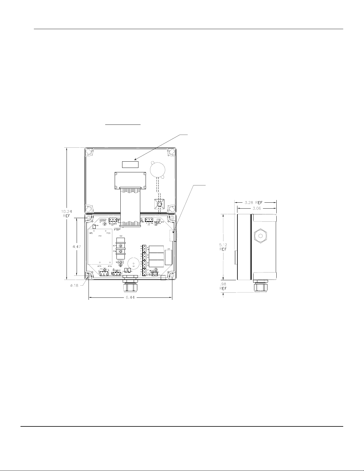
3.1 Mounting CP-10
Mount the CP-10 instrument on an appropriate vertical surface, leaving room for lid to be opened, using the mounting holes
provided. Avoid areas with excessive vibration or temperature extremes. The holes in the bottom of the enclosure are 0.18
inch in diameter and form a 6.44″ x 4.47″ rectangle. See Figure 3
It is recommended to use #8 drywall anchors and screws for mounting the CP-10 to a drywall/sheetrock surface.
Cover Inside View
Opened Upward
Attached to Base
Sensor Heater Voltage Label
Access for Sensor / Remote Sensor Wiring
Dimensions are in inches.
F
IGURE
3: Mounting CP-10
4
Page 7

CP-10 ENMET Corporation
1 2 3
Caution
3.1.1 Wiring the CP-10
The electrical installation should conform to appropriate electrical codes, such as the National Electrical Code in the United
States.
W
ARNING
:
The compliance of the installation to appropriate codes is not ENMET’s responsibility.
The CP-10 should be powered through appropriately sized circuit breakers. See Section 6.0 Technical Data.
3.1.2 Power Supply
The input power can vary from 100 to 240 VAC, 50/60 Hz. Power should be connected to the Power Input Terminal TB1 and
the Ground screw. See Figure 4 for location.
For DC wiring 24VDC may be wired to J12, (J12-1)position 1 + with ground connected to (J12-2)position 2.
Upon supplying power to the CP-10:
The green power on LED is lit.
The display backlight is lit, and instrument will step through a start-up sequence: unit serial number and software revision
may be shown on the display.
The instrument may go into alarm briefly, but the sensors stabilize quickly. If the instrument persists in alarm, acknowledge the
alarm by pressing the S
W
ARNING
:
Continuous gas detection and alarm systems (110VAC/220VAC / 24VDC/12VDC powered) become inoperative
upon loss of primary power. Contact factory for specifications and pricing of backup battery systems.
Sensor/Transmitter Terminal: J18
Position
1, V+
2, G Power Ground
3, Sig Signal/Return to Ground
Power +24 VDC
AC Power Supply Terminal: TB1
Label on PCB Function
110VAC
TB1 ACN Neutral
TB1 ACL Line
Ground
AC GND
Screw
ELECT
Function
button. If alarm persists longer than 30 minutes, call ENMET customer service personnel.
Cover Inside View
Opened Upward
220VAC
TB1 ACN Neutral
Optional TB1 ACL Line
Ground
AC GND
Screw
C
AUTION
: 110/220 VAC when applied
DC Power Supply/4-20mA
Terminal: J12
Position Function
1 +
2 GND
3 4 - 20 mA out
24 V
DC
power
F
IGURE
4: Power Terminal Connections CP-10
5
: 110/220 V
when applied
AC
Page 8

CP-10 ENMET Corporation
Heavier than Air Gas
Sensor Location
Bottled LP (liquefied petroleum)
Lighter
than Air Gas
Sensor Location
Natural gas (methane)
Same Density as Air Gas
Sensor Location
3.2. Sensor/Transmitter Connection
Sensor/Transmitters are connected to the CP-10 control unit with two or three-conductor wiring, use the correct oiltight fitting.
Size of wire depends on the distance between the sensor/transmitter and the control unit.
See Recommended Wire Gauge Table below.
2 Wire for Sensors/Transmitter
3 Wire for Sensors/Transmitter
Position Function Position Function
1, V+
2, G
3, Sig
Power +24 VDC
Not Used
Signal/Return to Ground
1, V+
2, G
3, Sig
Power +24 VDC
Power Ground
Signal
Recommended Wire Gauge
Distance from Sensor to Control Unit
< 500 feet 16 AWG
501 – 800 feet 14 AWG
Longer Distances Contact Factory
Recommended Wire Gauge
N
OTE
: Sensor Location
Gases have different densities. Some are heavier than air and concentrate at the bottom of a space. Some are lighter than air
and gather at the top. Consider the density of the gas you want the sensor to detect when you install the sensor. Some
examples are given below.
Interior wall; 18-24" from floor.
Propane
Butane
Gasoline
Trichloroethylene
Vaporized hydrocarbons
Hydrogen sulfide
Ammonia
Hydrogen
Carbon Monoxide 4-6 feet above the (generally uniform) floor.
• DO N
OT
locate directly above or beside gas appliances (ovens,
heaters).
• Avoid locating anywhere near a vent or window or near an outside
doorway.
Near ceiling.
• DO N
OT
locate directly above appliances where it is subject to direct
exposure to heat or steam.
• DO N
OT
locate in direct air currents of windows, doors, or vents.
If you have a question involving the location of a unit or sensor, please contact your distributor or ENMET personnel. A
technician will analyze the question and recommend a location.
6
Page 9

CP-10 ENMET Corporation
Alarm
Position
Relay Terminals
Relays
Sensor/Transmitter
3.3 Relay Contacts
Relay contacts are available for each alarm; these are SPDT, rated at 10Amp at 110VAC, and may be latching or non-latching
as required by the application.
They are accessed on the terminals next to each relay see Figure 5. The contact positions are noted on the circuit board next to
each terminal.
The following table is for the relays in their un-energized state. This is also the alarm condition state. Non-failsafe configured
relays in the alarm state, are the reverse of the PC board labeling. Note that the Fault(FLT) relay cannot be set to operate in a
Non-Failsafe mode. Please see Table 1 below:
T
ABLE
1: Relay Failsafe Settings
J14 (K1)Relay 1 - NO Normally Open
Alarm 1
Alarm 2
Alarm 3
Fault Alarm
These relay contacts can be used to operate auxiliary alarms or other functions. The relay contacts are DRY, power must be
supplied. It is recommended that power for auxiliary equipment be supplied from an independent power source separate form
the CP-10. Use the existing hole in the enclosure for wire to enter and exit and use appropriate cable fittings. Wiring should
be grouped together, VAC wires should be separated for VDC wires.
Terminal J18
J14 (K1)Relay 1 - NC Normally Closed
J14 (K1)Relay 1 - COM Common
J15 (K2)Relay 2 - NO Normally Open
J15 (K2)Relay 2 - NC Normally Closed
J15 (K2)Relay 2 - COM Common
J16 (K3)Relay 3 - NO Normally Open
J16 (K3)Relay 3 - NC Normally Closed
J16 (K3)Relay 3 - COM Common
J17 (K4)Relay 4 - NO Normally Open
J17 (K4)Relay 4 - NC Normally Closed
J17 (K4)Relay 4 - COM Common
F
IGURE
J14, J15, J16, J17
K1, K2, K3, K4
5: Relay Terminal Connections CP-10
7
Page 10

CP-10 ENMET Corporation
CP-10
W
CP
-
10
130
-
1256
0ppW
0ppm
0LEL
20.9%
4.0 Operation
When the CP-10 is installed as described in Section 3, and in clean air, the POWER green LED is on, the display is lit and the
information on the display is measurement of the target detected by the CP-10. The red alarm and fault LEDs are not lit.
4.1 Start Up CP-10
When the CP-10 is first powered up, it goes through a series of momentary screens, which identify the instrument model number,
serial number and software revision. After all of the momentary screens have been displayed, the instrument arrives at the Main
Gas Display showing the gas concentration and unit of measurement in ppm, % or %LEL.
Depending on transmitter configuration and calibration condition, the furthest right character in the display may flash a letter
indicating the instrument status. See the Section 4.1.1 below
4.1.1 Typical Start Up
When power is supplied to the CP-10, the instrument will display the following sequence of information:
Typical start up sequence of information displayed.
Example of Typical Start Up Display Function
The instrument: Model
The instrument: Serial Number
Example for reference only
The instrument: Software Revision
S/W X.X
Example for reference only
IF the right most character is a flashing
N
OTE
:
Software revision may cause variations of display output.
The instrument is in Warm-up mode
This should last about 1 minute
The Signal Output is held at 4mA during warm-up
The instrument: Normal Display Mode
Measurement of the target gas
PPM Parts Per Million
% Percent By Volume
LEL Lower Explosive Limit
F Fault, Sensor/Transmitter is not connected or
wiring is not correct
8
Page 11

CP-10 ENMET Corporation
Example:
Select
Select
Select
Select
Select
4.2 Normal Display Mode
When the CP-10 is installed as described in section 3, the POWER green LED is on, the display is lit and the measurement
designator: ppm, LEL or % is displayed by the CP-10. The red alarm and fault LEDs are not lit.
To advance through displays of operational information press the M
N
OTE
:
Software revision may cause variations of display output.
See sequence of operational information below:
Display Measurement of the target gas
Press M
ENU
button
0ppm
Menu
ENU
button.
²
Display indicates Alarm 1 Set point
Press M
ENU
button
A1: 05
²
Menu
Display indicates Alarm 2 Set point
Press M
ENU
button
Display indicates Alarm 3 Set point
Press M
ENU
button
A2: 10
Menu
A3: 20
²
²
Menu
Display indicates mA Span range
(Full Scale)
Press M
ENU
button
mA: 50
Menu
²
Display returns to gas measurent
Operational Display Flow Chart
4.2.1 Alarm Conditions CP-10
There are three alarm set points available. These alarm points are normally set at established safety levels, such as the OSHA
Permissible Exposure Limit (PEL) for toxic gases or recognized standards below the Lower Explosive Limit for combustible
gases.
These alarm set points can be changed within limits; see the maintenance section of this manual for the procedure.
When the Oxygen, Toxic or combustible gas concentration reaches the alarm set point, the associated red LED is lit, the
associated relay changes state, and the audio alarm is activated.
Pressing the S
ELECT
button can temporally disable the Audio Alarm. The horn will be disabled for about five minutes. If a
second alarm condition occurs during this time the horn will re-activate. If the alarm condition(s) have ended during this time
the horn will not re-activate.
9
Page 12

CP-10 ENMET Corporation
Normal Display Mode
5ppm
Exit
420Setup
5.0 Maintenance
The CP-10 maintenance menus that are accessed by pressing the M
maintenance menu section.
5.1 Maintenance Menus
Pushbutton switches control the M
display panel, see Figure 1. The M
numbers such as alarm points. The S
To enter the maintenance menu press and hold the M
Table 2 indicates the maintenance menu sequence see Figure 6 for a detailed maintenance menu flow chart.
N
OTE
:
Software revision may cause variations of display output.
Example of Display Function
T
ABLE
ENU
and S
ELECT
functions. The M
ENU
button is used to display the various menu options and make incremental changes to
ELECT
button is used to select the option and move the cursor.
ENU
button for 2 to 4 seconds
2: CP-10 Maintenance Menus Sequence
ENU
button and S
ENU
and S
ELECT
Measurement of CO
ELECT
button as described in the
button locations are indicated on the
Press and hold the M
The Power/Fault LED will flash Green – Red to indicate the CP-10 is in Maintenance Mode
Press the M
Press the M
Alarm1
ENU
ENU
ENU
button for 2 – 4 seconds to enter the Maintenance Menu
To exit the maintenance Menu and return to the
Normal Display Mode:
If intended function Press S
button to advance to 4 & 20 Setup procedures
For adjusting the 4 and 20 mA circuit:
If Intended function Press S
button to advance to each Alarm set point procedures
For adjusting the Alarm 1, 2 and 3 set points:
If Intended function Press S
Alarm2
Alarm3
Press the M
Pressing the M
You must Press the S
ENU
button to advance the mA Span set point procedure
mA Span
ENU
button without pressing the S
ELECT
button in order to initiate the desired operation.
For adjusting the mA Span set point:
If intended function Press S
ELECT
button will allow you to cycle through the menu options.
ELECT
ELECT
ELECT
ELECT
button
button
button
button
10
Page 13

CP-10 ENMET Corporation
Menu
Select
Select
Select
Select
0
Select
50
Select
0
Select
mA Span
Select
To
0
SetTD
sec
0
5
SetTD
sec
0
Alarm2
S
5ppm
Normal Gas Display
Exit
Menu
420Setup
Menu
Alarm1
M
ENU
M
ENU
Alarm3
M
ENU
Press and H
OLD
the M
ENU
button for 2 – 4 seconds to enter the Maintenance Menus
Press the Select button to return to the Normal Gas Display. See Section 5.2.1
²
Press the Menu button to cycle through Maintenance Menus
Scale4mA
²
Menu
Scal20mA
²
Menu
mA Trim
²
Menu
S
ELECT
Λ
ELECT
Λ 10
S
ELECT
Λ 20
²
Press Select button to set low end of scale:
The Select button locks underscored digit and moves to next digit
The Menu button changes digit indicated by underscore cursor
When last digit is entered CP-10 will advance to full scale set up
²
Press Select button to advance to full scale
To set full scale :
The Select button locks underscored digit and moves to next digit
The Menu button changes digit indicated by underscore cursor
When last digit is entered CP-10 will advance to display trim
²
Press Select button to advance to display trim
To adjust display of CP-10 to match S/T display
The Select button locks underscored digit and moves to next digit
The Menu button changes digit indicated by underscore cursor
When the last digit has been locked in place, Cal OK will appear briefly than
the CP-10 will advance to the next menu, Alarm 1
See Section 5.2.2
To change Alarm set points:
Press Menu switch until Alarm to be changed is displayed
Press Select switch to display the set point
The M
cursor
The S
moves to next digit
If change is not within range display returns to first digit
If change is within range display moves to Set Time Delay
Use M
delay. Between 0 and 5 seconds is allowed
If change is within range display moves to next menu
See Section 5.2.3
Λ - Indicates increasing alarm
V - Indicates decreasing alarm
ENU
switch: changes digit indicated by underscore
ELECT
switch: locks in the underscored digit and
ENU
and S
ELECT
SetTDsec
Cal OK
switches as above to change time
0050
²
Menu
return to Normal Gas Display:
Press M
Then press S
N
OTE
:
Software revision may cause variations of display output.
ENU
button until EXIT is displayed
ELECT
button
F
IGURE 6:
CP-10 Maintenance Menu Flow Chart – Gas
To change mA Span set point:
Press Menu button until mA Span is displayed
Press Select button to display the set point
The Menu button changes digit indicated by underscore cursor
The Select button locks underscored digit and moves to next digit
See Section 5.2.4
11
Page 14

CP-10 ENMET Corporation
Menu
Select
mA Span
Select
30.0
To
Alarm3
23.5
SetTD
sec
0
Alarm1
17.0
SetTD
sec
0
Alarm2
Select
Select
Select
0.0
30.0
20.9
Select
Press Select button to set low end of scale:
Select
Select
Press
Select button to advance to display trim
Press Select button to advance to full scale
20.9%
Exit
Menu
420Setup
Menu
M
ENU
M
ENU
M
ENU
Normal Gas Display
Press and H
OLD
the M
ENU
button for 2 – 4 seconds to enter the Maintenance Menus
Press the Select button to return to the Normal Gas Display. See Section 5.2.1
²
Press the Menu button to cycle through Maintenance Menus
Scale4mA
²
Scal20mA
²
mA Trim
²
S
ELECT
S
ELECT
S
ELECT
Menu
Menu
Menu
V
V 19.5
Λ
SetTDsec
²
The Select button locks underscored digit and moves to next digit
The Menu button changes digit indicated by underscore cursor
When last digit is entered CP-10 will advance to full scale set up
²
To set full scale :
The Select button locks underscored digit and moves to next digit
The Menu button changes digit indicated by underscore cursor
When last digit is entered CP-10 will advance to display trim
²
To adjust display of CP-10 to match S/T display
The Select button locks underscored digit and moves to next digit
The Menu button changes digit indicated by underscore cursor
When the last digit has been locked in place, Cal OK will appear briefly than
the CP-10 will advance to the next menu, Alarm 1
See Section 5.2.2
To change Alarm set points:
Press Menu switch until Alarm to be changed is displayed
Press Select switch to display the set point
The M
ENU
cursor
The S
moves to next digit
If change is not within range display returns to first digit
If change is within range display moves to Set Time Delay
Use M
delay. Between 0 and 5 seconds is allowed
If change is within range display moves to next menu
See Section 5.2.3
Λ - Indicates increasing alarm
V - Indicates decreasing alarm
switch: changes digit indicated by underscore
ELECT
switch: locks in the underscored digit and
ENU
and S
ELECT
Cal OK
switches as above to change time
Menu
return to Normal Gas Display:
Press M
Then press S
N
OTE
:
Software revision may cause variations of display output.
0
²
ENU
button until EXIT is displayed
ELECT
button
F
IGURE 7:
CP-10 Maintenance Menu Flow Chart – Oxygen
To change mA Span set point:
Press Menu button until mA Span is displayed
Press Select button to display the set point
The Menu button changes digit indicated by underscore cursor
The Select button locks underscored digit and moves to next digit
See Section 5.2.4
12
Page 15

CP-10 ENMET Corporation
Example of Exit menu:
Select
Select
Select
Select
Select
Select
mA Trim
Cal OK
Select
5.2 CP-10 Maintenance Adjustments
To set alarm points and 4-20mA span range enter the CP-10 maintenance menu.
To enter the maintenance menu press and hold the M
N
OTE
:
Software revision may cause variations of display output.
5.2.1 Exit Maintenance Menu
Exit maintenance, by pressing the Exit appears on the display. Press the S
Display.
Exit
Press the Select button to return to the Normal Gas Display.
²
Menu
Press the Menu button to cycle through Maintenance Menus
5.2.2 Set Up 4 and 20 Scale
The CP-10 4 mA low scale (the low end of range) and 20 mA full scale (the high end of range) is set at the factory. The mA
Trim is for the adjustment of miner differences that may occur between the CP-10 control and the S/T display.
To Set up the low and full scale mA values or the trim of the readings:
Enter the maintenance menu as shown in Figure 6 & Figure 7 CP-10 Maintenance Menu flow chart.
1. Press the M
2. Press the S
Note: to advance to the next menu without changing this scale setting Press the M
3. Press the S
4. Press the S
5. Press the M
repeat steps 4 & 5, When last digit is entered the CP-10 will advance to the next menu.
Note: when mA Trim last digit has been entered, Cal OK will be displayed briefly and CP-10will advance to Alarm 1.
6. Press the M
Example of 4 – 20 mA Scale Setup menus:
420Setup
Menu
ENU
button until to 420Setup is displayed.
ELECT
button to enter 4 mA low end of scale set up.
ELECT
button to initiate 4 mA low end of scale set up.
ELECT
button to move the cursor to the next digit.
ENU
button to change the digit indicated by the underscore cursor.
ENU
button to advance to the next menu
Scale4mA
²
Menu
ENU
button for 2 to 4 seconds
ELECT
button to return to the instrument Normal Gas
0
²
Press Select button to set low end of scale:
The Select button locks underscored digit and moves to next digit
The Menu button changes digit indicated by underscore cursor
When last digit is entered CP-10 will advance to full scale set up
ENU
button
Scal20mA
²
Menu
²
Menu
50
²
Press Select button to advance to full scale
To set full scale :
The Select button locks underscored digit and moves to next digit
The Menu button changes digit indicated by underscore cursor
When last digit is entered CP-10 will advance to display trim
²
0
Press Select button to advance to display trim
To adjust display of CP-10 to match S/T display
The Select button locks underscored digit and moves to next digit
The Menu button changes digit indicated by underscore cursor
When the last digit has been locked in place, Cal OK will appear briefly than
the CP-10 will advance to the next menu, Alarm 1
13
Page 16

CP-10 ENMET Corporation
Example of Alarm Set Point menus:
Example of mA Span menu:
mA Span
Select
0050
Alarm1
17.0
SetTD
se
0
SetTD
se
5.2.3 Alarm Set Points
The CP-10 has three alarm set points set at the factory. These alarm points are normally set at established safety levels. Alarm
set points can be changed within limits. To change any of the three alarm points:
Enter the maintenance menu as shown in Figure 6 & Figure 7 CP-10 Maintenance Menu flow chart.
1. Press the M
2. Press the S
3. Press the M
Λ - Indicates increasing alarm
V - Indicates decreasing alarm
4. Press the S
When last digit is entered the CP-10 will advance to the next menu
5. Use M
6. Press the M
N
OTE
: Alarms 2 and 3 can not be set below the Alarm 1 setting.
M
ENU
Alarm2
M
ENU
Alarm3
ENU
ENU
button until to display Alarm1 is displayed.
ELECT
button to initiate alarm set point change
ENU
button to change the digit indicated by the underscore cursor
ELECT
button to move the cursor to the next digit
and S
ELECT
switches as above to change time delay. Between 0 and 5 seconds is allowed.
ENU
button to advance to the next menu
Gas
S
ELECT
S
ELECT
S
ELECT
OR
Λ 5
SetTDsec
0
Λ 10
SetTDsec
0
Λ 20
Oxygen
V
SetTDsec
0
V 19.5
SetTDsec
0
Λ 23.5
To change Alarm set points:
Press Menu switch until Alarm to be changed is displayed
Press Select switch to display the set point
The M
ENU
switch: changes digit indicated by underscore
cursor
The S
ELECT
switch: locks in the underscored digit and
moves to next digit
If change is not within range display returns to first digit
If change is within range display moves to Set Time Delay
Use M
ENU
and S
ELECT
switches as above to change time
delay. Between 0 and 5 seconds is allowed
If change is within range display moves to next menu
Λ - Indicates increasing alarm
V - Indicates decreasing alarm
M
ENU
0
N
OTE
:
Software revision may cause variations of display output.
5.2.4 mA Span Set
The CP-10 4-20mA span range is set at the factory, normally to the full scale of the measurement and can be changed within
limits. To change the span range:
Enter the maintenance menu as shown in Figure 6 CP-10 Maintenance Menu flow chart.
1. Press the M
2. Press the S
3. Press the M
4. Press the S
When last digit is entered the CP-10 will advance to the next menu
5. Press the M
Menu
ENU
button until to display Span is displayed.
ELECT
button to initiate the mA Span menu
ENU
button to change the digit indicated by the underscore cursor
ELECT
button to move the cursor to the next digit
ENU
button to advance to the next menu
²
To change mA Span set points:
Press Menu button until mA Span is displayed
Press Select button to display the set point
The Menu button changes digit indicated by underscore cursor
The Select button locks underscored digit and moves to next digit
14
Page 17

CP-10 ENMET Corporation
6.0 Technical Data and Specifications
The CP-10 technical data and specifications:
Electrical Power 15 Amp fused branch circuit
100-240 VAC
0.45A, 50/60 Hz
0.6A, 24VDC
Storage and Transport Temperature:
preferred
Relative Humidity
Atmospheric Pressure
Operation Temperature:
Relative Humidity
Atmospheric Pressure
Mechanical Dimensions:
Weight:
Material:
Strain relief:
Outputs Relays:
Analog:
Digital:
Audio:
N
OTE
: All specifications stated in this manual may change without notice.
-20° to +60°C (-4° to +140°F)
0° to +20°C (32° to 68°F)
10-99% RH, non-condensing
20 to 36 inHg (68 to 133 kPa)
-15° to +40°C (5° to +104°F)
10-99% RH, non-condensing
20 to 36 inHg (68 to 133 kPa)
7.1 x 5.1 x 3 in(180x130x75mm)
2 lbs (0.9 kg)
Polycarbonate
0.20 – 0.35 in(5 - 8.8mm)
SPDT
Resistive Load Inductive Load
10A at 110 VAC 7.5A at 110 VAC
10A at 30 VDC 5A at 30 VDC
4-20mA
RS-485-modbus
105 dB at 30cm/12in
15
Page 18

CP-10 ENMET Corporation
7.0 WARRANTY
ENMET warrants new instruments to be free from defects in workmanship and material under normal use for a period of one
year from date of shipment from ENMET. The warranty covers both parts and labor excluding instrument calibration and
expendable parts such as calibration gas, filters, batteries, etc... Equipment believed to be defective should be returned to
ENMET within the warranty period (transportation prepaid) for inspection. If the evaluation by ENMET confirms that the
product is defective, it will be repaired or replaced at no charge, within the stated limitations, and returned prepaid to any
location in the United States by the most economical means, e.g. Surface UPS/FedEx Ground. If an expedient means of
transportation is requested during the warranty period, the customer is responsible for the difference between the most
economical means and the expedient mode. ENMET shall not be liable for any loss or damage caused by the improper use of
the product. The purchaser indemnifies and saves harmless the company with respect to any loss or damages that may arise
through the use by the purchaser or others of this equipment.
This warranty is expressly given in lieu of all other warranties, either expressed or implied, including that of merchantability,
and all other obligations or liabilities of ENMET that may arise in connection with this equipment. ENMET neither assumes
nor authorizes any representative or other person to assume for it any obligation or liability other than that, which is set forth
herein.
NOTE: When returning an instrument to the factory for service:
Be sure to include paperwork.
A purchase order, return address and telephone number will assist in the expedient repair and return of your unit.
Include any specific instructions.
For warranty service, include date of purchase
If you require an estimate, please contact ENMET Corporation.
There are Return for Repair Instructions and Form on the last pages of this manual. This Form can be copied or used as needed.
Manual part number
80003-502
Original April 2007
MCN-377, 07/26/07
MCN-384, 10/11/07
MCN-420, 04/22/09
Notes:
16
Page 19

PO Box 979
680 Fairfield Court
Ann Arbor, Michigan 48106-0979
734.761.1270 Fax 734.761.3220
Returning an Instrument for Repair
ENMET instruments may be returned to the factory or any one of our Field Service Centers for regular repair
service or calibration. The ENMET Repair Department and Field Service Centers also perform warranty
service work.
When returning an instrument to the factory or service center for service, paperwork must be included which
contains the following information:
A purchase order number or reference number.
A contact name with return address, telephone and fax numbers
Specific instructions regarding desired service or description
of the problems being encountered.
Date of original purchase and copy of packing slip or invoice
for warranty consideration.
If a price estimate is required, please note it accordingly and be
sure to include a fax number.
Providing the above information assists in the expedient repair and return of your unit.
Failure to provide this information can result in processing delays.
ENMET charges a one hour minimum billing for all approved repairs with additional time billed to the closest
tenth of an hour. All instruments sent to ENMET are subject to a minimum evaluation fee, even if returned
unrepaired. Unclaimed instruments that ENMET has received without appropriate paperwork or attempts to
advise repair costs that have been unanswered, after a period of 60 days, may be disposed of or returned
unrepaired COD with the evaluation fee.
Service centers may have different rates or terms. Be sure to contact them for this information.
Repaired instruments are returned by UPS/FedEx Ground and are not insured unless otherwise
specified. If expedited shipping methods or insurance is required, it must be stated in your paperwork.
Note: Warranty of customer installed components.
If a component is purchased and installed in the field, and fails within the warranty term, it can be
returned to ENMET and will be replaced, free of charge, per ENMET’s returned goods procedure.
If the entire instrument is returned to ENMET Corporation with the defective item installed, the item will
be replaced at no cost, but the instrument will be subject to labor charges at half of the standard rate.
Page 20

Mailin
g Address:
Shipping Address:
Repair Return Form
ENMET Corporation
PO Box 979
Ann Arbor, Michigan 48106
Phone Number: 734.761.1270
FAX Number: 734.761.3220
Your Mailing Address:
Contact Name: __________________________ Your Phone: _______________________
Your PO/Reference Number: _______________ Your FAX: _______________________
ENMET Corporation
Attn: Repair Department
680 Fairfield Court
Ann Arbor, Michigan 48108
Your Shipping Address:
Payment Terms: K COD
(Check one) K VISA / MasterCard______________________ ________ ________
Card number Expiration Card Code
K American Express______________________ ________ ________
Card number Expiration Card Code
Name as it appears on the credit card___________________________________
Return Shipping Method:
K UPS: K Ground K 3 Day Select K Next Day Air K ND Air Saver K 2-Day Air
K UPS Account number: ________________________
K Federal Express: K Ground K Express Saver K P-1 K Standard K 2-Day Air
K FedEx Account number: ________________________
Would you like ENMET to insure the return shipment?
K No K Yes Insurance Amount: $_________________
 Loading...