

Page 1

ENMET Corporation
PO Box 979
Ann Arbor, MI 48106-0979
www.enmet.com
CD-1300-ST Series
CO2 Sensor/Transmitter
Manual
Manual Part Number
80003-134
MCN-13-004, 06/24/13
Page 2

Table of Contents
1.0 I
NTRODUCTION
1.1 Unpack.............................................................................................................................................................. 1
1.2 Check Order ..................................................................................................................................................... 1
1.3 Serial Numbers ................................................................................................................................................. 1
2.0 F
EATURES
2.1 Display and Indicators ...................................................................................................................................... 2
2.2 Specifications ................................................................................................................................................... 2
3.0 I
NSTALLATION
3.1 Removal of Cover............................................................................................................................................. 3
3.2 Mounting .......................................................................................................................................................... 3
3.3 Wiring ............................................................................................................................................................... 3
3.3.1 Power supply .......................................................................................................................................... 4
3.3.2 Signal Output .......................................................................................................................................... 4
3.3.3 Voltage ................................................................................................................................................... 4
3.3.4 Current ................................................................................................................................................... 4
3.4 Verifying Voltage or Current Output Connection ............................................................................................ 4
3.4.1 Cover Replacement ................................................................................................................................. 4
4.0 F
IELD ADJUSTMENTS
4.1 Analog Output Range Adjustment.................................................................................................................... 5
4.2 Altitude Correction ........................................................................................................................................... 6
4.2.1 Altitude Correction Procedure ............................................................................................................... 6
5.0 C
ALIBRATION
5.1 Verification Procedure ...................................................................................................................................... 6
5.2 High CO2 Limit ................................................................................................................................................ 7
5.2.1 Adjusting the High CO2 Limit ................................................................................................................. 7
5.2.2 Optional High Limit Contact .................................................................................................................. 7
5.2.3 Setting High Limit Contact Polarity ....................................................................................................... 7
6.0 D
UCT SAMPLING OPTION
6.1 Overview .......................................................................................................................................................... 8
6.1.1 Duct Kit Contents ................................................................................................................................... 8
6.1.2 Duct Kit Installation ............................................................................................................................... 8
7.0 WARRANTY ........................................................................................................................................... 9
.......................................................................................................................................... 1
................................................................................................................................................. 2
........................................................................................................................................... 3
................................................................................................................................. 5
............................................................................................................................................ 6
........................................................................................................................... 8
List of Illustrations
F
IGURE 1:
F
IGURE 2:
T
ABLE 1: ALTITUDE CORRECTION
F
IGURE 3: DUCT SAMPLING SCHEMATIC
F
IGURE 4: DUCT PROBE INSTALLATION DIMENSIONS
CD-1300-ST S
CD-1300-ST S
ERIES, MOUNTING DIMENSIONS
ERIES COMPONENT LOCATION
................................................................................. 3
.................................................................................. 3
..................................................................................................................... 6
........................................................................................................... 8
......................................................................................... 8
Page 3

CO2 Sensor / Transmitter ENMET Corporation
1.0 Introduction
The CD-1300-ST Series Sensor/Transmitter (S/T) are a non-dispersive infrared analyzer for measuring environmental CO2
concentration in ventilation systems and indoor living spaces. Its measurement range of 0 – 2000 ppm (parts per million;
1000ppm = 0.1%) covers the range required to monitor compliance with ASHRAE or other ventilation efficiency standards.
For optional range of 0 – 5000 ppm see section 4.1 Analog Output Range adjustment.
Packaged in a compact, distinctively styled enclosure, the CD-1300-ST Series can be discreetly installed anywhere from the
board room to the boiler room. Standard center wiring access and fully floating outputs make installation a snap. The CD1300-ST Series provides several output alternatives. A voltage or 4 - 20 mA current output is standard. An optional LCD
readout is available. An optional relay contact can be configured to open or close above a user-adjustable setpoint. A simple
one-point calibration procedure and a built-in calibration port that requires no special fittings or adapters make the CD-1300-ST
Series simple to maintain.
N
OTE
: All specifications stated in this manual may change without notice.
1.1 Unpack
Unpack the CD-1300-ST series and examine it for shipping damage. If such damage is observed, notify both ENMET
customer service personnel and the commercial carrier involved immediately.
Regarding Damaged Shipments
N
OTE
: It is your responsibility to follow these instructions. If they are not followed, the carrier will not honor
any claims for damage.
This shipment was carefully inspected, verified and properly packaged at our company and delivered to the carrier in
good condition.
When it was picked up by the carrier at ENMET, it legally became your company’s property.
If your shipment arrives damaged:
• Keep the items, packing material, and carton “As Is.” Within 5 days of receipt, notify the carrier’s local office and
request immediate inspection of the carton and the contents.
• After the inspection and after you have received written acknowledgment of the damage from the carrier, contact
ENMET Customer Service for return authorization and further instructions. Have your Purchase Order and Sales
Order numbers available.
ENMET either repairs or replaces damaged equipment and invoices the carrier to the extent of the liability coverage,
usually $100.00. Repair or replacement charges above that value are your company’s responsibility.
The shipping company may offer optional insurance coverage. ENMET only insures shipments with the shipping
company when asked to do so in writing by our customer. If you need your shipments insured, please forward a written
request to ENMET Customer Service.
Regarding Shortages
If there are any shortages or questions regarding this shipment, please notify ENMET Customer Service within 5 days of
receipt at the following address:
ENMET Corporation
680 Fairfield Court
Ann Arbor, MI 48108
734-761-1270 734-761-3220 Fax
1.2 Check Order
Check, the contents of the shipment against the purchase order. Verify that the CD-1300-ST series is received as ordered. If
there are accessories on the order, ascertain that they are present. Check the contents of calibration kits. Notify ENMET
customer service personnel of any discrepancy immediately.
1.3 Serial Numbers
Each CD-1300-ST series is serialized. These numbers are on tags on the equipment and are on record in an ENMET database.
1
Page 4
CO2 Sensor / Transmitter ENMET Corporation
2.0 Features
2.1 Display and Indicators
The basic CD-1300-ST Series has a single green LED on the front panel which illuminates whenever the unit is operating.
This LED is on steadily when the measured concentration is below the high CO2 limit, and blinks whenever the concentration is
above the limit.
The standard factory high limit is 1000 ppm, but can be easily adjusted in the field. The procedure for adjusting the high CO
limit is described in Section 5.2.
The display option adds a 4 digit liquid crystal display (LCD) to the front panel. The display shows the measured CO2
concentration in parts per million (ppm). 1000 parts per million equals 0.1%.
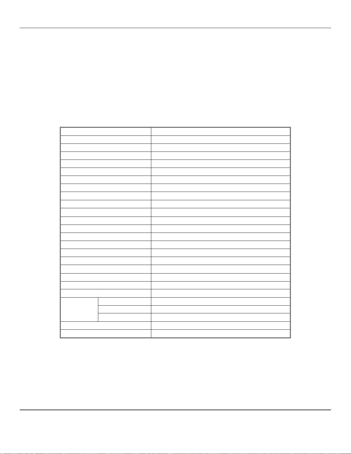
2.2 Specifications
2
Operating principle
Gas sampling method
Measurement range
Typical drift (per year)
Accuracy
Repeatability
Recommended Calibration Interval
Response time
Operating temperature range
Operating humidity range
Storage temperature
Power requirements
Power consumption
Calibration adjustments
Calibration verification time
Dimensions
Voltage output (linear)
Current output (linear)
Warm-up time
Weight
Optional Digital Display
Optional
High Limit
Contact
setpoint range
contact polarity
contact rating
Operating life expectancy
Warranty
Non-dispersive infrared (NDIR)
Diffusion or sample draw
0 – 2000 ppm CO2, Optional 0 – 5000 ppm
±75 ppm (@ 1200ppm)
±5% of reading or ±75 ppm, whichever is greater
±20 ppm
One Year
Less than 1 minute
0 to 50 ° C
0 - 90% RH (non condensing)
-30 to + 60 ° C
20 – 28 V
RMS
AC, 18 - 30 VDC
Less than 2W @ 24 VAC
Span only (offset electronically nulled)
10 minutes typical
5.2" x 3.2" x 1.4"
0 – 10 volts DC standard
4 - 20 mA (R
≤ 500Ω)
L
3 minutes
6.5 Oz. (0.35 Kg)
4 digit, .35" LCD
0 to full scale
jumper selectable
2A @ 24 VAC
10 years typical
12 months, parts and labor through repair or exchange
N
OTE
: All specifications stated in this manual may change without notice.
2
Page 5

CO2 Sensor / Transmitter ENMET Corporation
″
0.406
″
″
″
″
″
Ground
J5
J5
Upper Mounting
Lower Mounting
Relay Contact
Signal Ground
20mA
Jumper Here for
Current
O
UTPUT
Jumper Here for
Voltage
O
UTPUT
Down Button
Up Button
User Jumpers
3.0 Installation
3.200″
2103″.
1.600″
1.103″
0.000″
0.000
2.003
2.753
3.562
5.200
Figure 1: CD-1300-ST Series, Mounting Dimensions
3.1 Removal of Cover
To open the CD-1300-ST series use a coin in the slot on the bottom to release the snap. Lift the cover up slightly to disengage
the closure and remove cover with a downward motion to clear the catch at the top of the unit. The locations of controls and
terminals on the main circuit board are shown in the Figure 2.
3.2 Mounting
The CD-1300-ST series is designed for flush mounting with two fasteners. The locations of the mounting points (shown in
Figure 1) allow direct mounting on a standard simplex (single circuit) junction box. There is a wiring cutout in the center of the
unit near the terminal strips.
3.3 Wiring
This section describes the external connections to the CD-1300-ST Series. Wiring enters the chassis through the cutout in the
center of the unit.
C
USTOMER WIRING NOTE
When connecting to ENMET CP-10, CP-60,
LC-8 or other 3-wire type controllers:
1.) Preferred wiring for long runs,
use 4-wire cable, connect +24VDC, Power
Ground, Signal Ground & 4-20mA at
transmitter and Connect both Power
Ground & Signal Ground together to
ground at the Controller.
2.) Alternative wiring for short runs,
use 3-wire cable and jumper Power
and Signal Ground together inside the
transmitter.
:
JP5
JP4
JP3
JP2
Option Button
4-
SW3
JP1
UP
SW1
SW2
M
DN
U3
Microprocessor
Sensor
Screw Access
Wiring Access
+ 24VDC
Power Ground
Figure 2: CD-1300-ST Series Component Location
3
Screw Access
Page 6

CO2 Sensor / Transmitter ENMET Corporation
3.3.1 Power supply
The CD-1300-ST series will operate from an AC or DC input voltage between the values called out in the specifications in
section 2.2. The power supply leads are connected to the two-terminal power connector shown in Figure 2.
The CD-1300-ST series must never be connected directly to line power.
Operation at voltages higher than specified will damage the unit and void the warranty. When operating from DC power, the
polarity of the power leads must be as shown in Figure 2. Reversed polarity connection will not damage the unit, but will make
it inoperable until the connection is reversed.
3.3.2 Signal Output
The CD-1300-ST series provides either a 0 – 10 volt or a 4-20mA current loop output at the two terminals of the analog output
connector shown in Figure 2. The type of analog output is determined by the setting of the analog output selector shown in Figure
2. The analog output of the CD-1300-ST Series is completely isolated from the power supply. The common outputs of multiple
units can be connected together with no interaction regardless of power supply hook-up.
3.3.3 Voltage
When the outboard and middle pins of the analog output selector are connected with the shorting block, a voltage output
appears between the two terminals marked ANALOG OUTPUT. The output voltage increases linearly from
0 volts at the low output threshold to 10 volts at the high output threshold. The unit is shipped from the factory with the low
output threshold at 0 ppm and the high output threshold at 2000 ppm. See section 4.1 the Analog Output Range Adjustment to
change the analog output range limits.
3.3.4 Current
When the inboard and middle pins of the analog output selector are connected with the shorting block, a current output appears
between the two terminals marked ANALOG OUTPUT. The output current increases linearly from 4 mA at the low output
threshold to 20 mA at the high output threshold. The unit is shipped from the factory with the low output threshold at 0 ppm
and the high output threshold at 2000 ppm. See section 4.1 the Analog Output Range Adjustment to change the analog output
range limits. If the total resistance between the two terminals exceeds the specified maximum loop resistance, the output
current may be erroneously low at high concentrations.
3.4 Verifying Voltage or Current Output Connection
After the voltage or current output of the CD-1300-ST Series is connected to a controller or indicator, the following check
should be performed to ensure that the connection has been properly established and the CD-1300-ST Series is transmitting the
correct values:
1. Be sure that the output select jumper is set correctly for voltage or current output. If this is not done first, the following
check may produce incorrect results.
N
OTE
whether the shorting block at jumper JP5 is covering both pins or only a single pin, then borrow the shorting block
and slide it over the two pins of jumper JP4 (see Figure 2). The display (if present) will show ‘SEL’
2. Momentarily closing JP5 will set the unit to full-scale output (10V or 20mA). Do not press the buttons on the unit, as this
will affect the output calibration.
If the receiving device does not indicate a full scale reading after JP5 is closed, verify that the wiring is correct.
3. Remove the shorting block from JP4 and restore it to its original position at jumper JP5. The CD-1300-ST Series will reset
and its output now corresponds to the actual detected CO2 concentration.
3.4.1 Cover Replacement
Engage the top center of the cover under the latch at the top of the base, then press the bottom of the cover onto the base until it
latches.
4
Page 7

CO2 Sensor / Transmitter ENMET Corporation
4.0 Field Adjustments
This section describes the features that can be field configured and the procedures to make these changes.
4.1 Analog Output Range Adjustment
This section refers to advanced features of the CD-1300-ST Series.
2000 ppm users need not perform this adjustment.
The CD-1300-ST series ships from the factory set for an analog output range of 0 to 2000 ppm. This range can be changed
to any sub-range between 0 and 5000 ppm by changing two parameters:
The low output threshold is the concentration at which the analog output will begin to rise. The factory default low output
threshold value is 0.
The high output threshold is the concentration at which the analog output reaches its maximum value. The factory default
high output threshold value is 2000.
For example, a particular application may require the analog output to remain at 0V or 4.0 mA until the gas concentration
reaches 500 ppm, then reach 10V or 20 mA at a concentration of 1000 ppm. In this example the analog output would scale
across this 500 ppm sub-range so that the analog output would be at half scale (5V or 12 mA) at 750 ppm.
To change the analog output range use the following procedure:
1. N
OTE
whether the shorting block at jumper JP5 is covering both pins or only a single pin, then borrow the shorting
block and slide it over the two pins of jumper JP4 (see Figure 2 Section 3.3). The display (if present) will show ‘SEL’.
2. The display (if present) will show ‘SEL’. Momentarily closing a jumper selects which value to change. If the wrong jumper
is selected simply open JP4 to restart the unit and begin again.
3. Select the low output threshold by momentarily closing JP1.
If the display is present it will show the current low display threshold. If there is no display the value can be displayed using a
meter connected to the analog output. In this calibration mode the analog output is 10,000 ppm at full scale (i.e. 10.0 volts or
20.0 mA). If the voltage output is selected, this scaling corresponds to 1 ppm per millivolt or 1000 ppm per volt.
4. Use the ‘UP’ and ‘DOWN’ buttons to adjust the low output threshold to the desired value. In the example this would be set to
500.
5. Remove the shorting block from JP4 to save the value; the unit will reset itself.
6. Reconnect JP4. The display (if present) will show ‘SEL’. Select the high output threshold by momentarily closing JP2. If
present, the display will show the high output threshold. If there is no display use a voltmeter as described in step 3.
7. Use the ‘UP’ and ‘DOWN’ buttons to adjust the high output threshold to the desired value. In the example this would be set
to 1000.
8. Remove the shorting block from JP4 and restore it to its original position at jumper JP5. CD-1300-ST series will reset and
its output will now only change when the gas concentration is within the range selected. Below this range the output remains
low, above this range the output remains high.
5
Page 8

CO2 Sensor / Transmitter ENMET Corporation
4.2 Altitude Correction
The CD-1300-ST series is factory-calibrated for operation at sea level. When operated at higher elevations, the calibration
must be adjusted by the amount shown in the altitude correction table to the right.
Table 1: Altitude Correction
Altitude [ft]
500 1.02
1000 1.03
1500 1.05
2000 1.07
2500 1.08
3000 1.10
3500 1.12
4000 1.14
4500 1.16
5000 1.18
Multiplication
Factor
0 1.0
4.2.1 Altitude Correction Procedure
To adjust the calibration of a unit currently calibrated for sea level operation to a new altitude proceed as follows:
1. Let the CD-1300-ST Series stabilize to the ambient CO2 concentration, and record the reading in ppm.
2. Multiply the reading by the scale factor corresponding to the operating altitude in the altitude correction table. For instance if
the unit is operating at an altitude of 4000 ft, the scale factor from the table is 1.14. If the concentration reads 420 ppm,
multiply 420 times 1.14 giving 478 ppm. Adjust the display to read 480.
3. Remove the CD-1300-ST Series’ cover (see cover removal procedure on Section 3.1).
4. N
OTE
whether the shorting block at jumper JP5 is covering both pins or only a single pin, then borrow the shorting
block and slide it over the two pins of jumper JP2 (see Figure 2 Section 3.3). Use the 'UP' and 'DOWN' buttons to change the
concentration to the value just calculated.
5. Remove the shorting block from jumper JP2 and return it to its previous position over one or both pins of jumper JP5.
6. Replace the cover (see procedure on Section 3.4.1).
5.0 Calibration
This section describes the calibration verification procedure and calibration adjustment procedures.
5.1 Verification Procedure
A quick but approximate calibration verification can be done by supplying the unit with outside air and letting the reading
stabilize. CO2 concentrations in outside air are typically between 350 and 450 ppm. A more accurate calibration check requires
the use of calibration gas of known concentration. Calibration materials are available from the factory or your local distributor.
Description ENMET part number
Regulator 02506-005
Cylinder CO2 1000ppm 03223-1000
Cylinder CO2 2000ppm 03223-2000
Cylinder CO2 5000ppm 03223-5000
6
Page 9

CO2 Sensor / Transmitter ENMET Corporation
To verify the CD-1300-ST Series's calibration, proceed as follows:
*N
OTE
: For instruments with serial numbers of 19180 and below the steps 3 and 4 must be reversed.
1. Remove the front cover of the unit (see procedure Section 3.1).
2. If there is no display on the unit being calibrated, connect a current or voltmeter to the analog output terminals. Check the
setting of the analog output selector (see Figure 2 Section 3.3) to determine whether the unit is set for voltage or current
output.
*3. N
OTE
whether the shorting block at jumper JP5 is covering both pins or only a single pin, then borrow the shorting
block and slide it over both pins of jumper JP2 (see Figure 2 Section 3.3).
*4. Remove the dust cover from the calibration nipple, attach regulator to cylinder of CO2 (remove quick release from tubing)
attach the tubing to calibration nipple and allow CO2 to flow for 1 to 2 minutes or until reading is stable.
5. If the reading differs by more than ± 75 ppm from the known concentration of the calibration gas, use the 'UP' and 'DOWN'
buttons (see Figure 2 Section 3.3) to adjust the reading.
6. When the reading agrees with the concentration of the calibration gas, remove the shorting block on jumper JP2, and replace
in its original position at jumper JP5.
7. Turn off the calibration gas flow, disconnect the gas tubing from the calibration nipple and replace its dust cover. Remove the
meter leads from the terminal strip and replace the front cover (see procedure Section 3.4.1).
5.2 High CO2 Limit
An adjustable high CO2 limit is a standard feature of the CD-1300-ST Series. The front panel LED changes from steady to
blinking when the indicated concentration is above the high CO2 limit value. An optional contact closure is available which
opens or closes when the high limit is exceeded.
5.2.1 Adjusting the High CO2 Limit
The setpoint value is adjusted by closing jumper JP3 (see Figure 2 Section 3.3). If the display is present when JP3 is closed it
will show the current high limit setpoint in ppm CO2.
If there is no display this setting can be adjusted by using a meter connected to the output. In this calibration mode the analog
output is 10,000 ppm at full scale (i.e. 10.0 volts or 20.0 mA). If the voltage output is selected, this scaling corresponds to
1ppm per millivolt or 1 volt per 1000 ppm.
The setpoint is adjusted with the ‘UP’ and ‘DOWN’ buttons while JP3 is closed. When JP3 is opened, the new relay setpoint
takes effect and is stored in non-volatile memory.
The setpoint hysteresis is approximately 40 ppm.
5.2.2 Optional High Limit Contact
The high CO2 limit option provides a dry (i.e. unpowered) contact closure that activates when the detected concentration rises
above the high CO2 limit. The high limit is adjustable from 0 to full scale of the unit
5.2.3 Setting High Limit Contact Polarity
The polarity of the high limit contact is set with jumper JP5 as shown in the table below.
Jumper JP5 Relay Operation
OPEN normally closed opens above setpoint
CLOSED (factory default) normally open closes above setpoint
To open jumper JP5 remove the shorting block from the two pins, and replace it so that it engages only a single pin of the
jumper. The shorting block should not be removed; it is required during the calibration procedure.
7
Page 10

CO2 Sensor / Transmitter ENMET Corporation
5/8’’
Drill 9/64’’
Drill 5/16’’
1 1/4’’
2 1/2’’
1 11/16’’
1 5/16’’
1 5/16’’
1/2’’
3’’
6.0 Duct Sampling Option
A
IR FLOW
1/8’’ ID Tube
Figure 3: Duct Sampling Schematic
6.1 Overview
The duct sampling option is used to divert a portion of the duct airflow through the CD-1300-ST Series. The difference between
the total pressure at the upstream sample port and the static pressure at the downstream return port propels the sample stream.
Minimum recommended flow rate is 200 feet per minute.
A CD-1300-ST series with the duct sample option has a sample draw adapter fitted to the bottom of its enclosure. The duct
probe assembly is connected to tubing nipples on the adapter.
6.1.1 Duct Kit Contents
K1 dust filter, K1 duct probe assembly, K2 sheet metal screws, K2 lengths of 1/8” ID tubing
6.1.2 Duct Kit Installation
1. Select a point along the duct where the probe assembly can be installed into unrestricted airflow without interfering with any
internal duct components such as dampers, radiators, etc.
2. Mark and drill the four holes for the duct probe as shown in Figure 4. The centerline must be parallel to the air flow through
the duct.
3. Install the duct probe assembly through the holes just drilled. The sample port must be on the upstream side. Secure the
probe assembly in place with the two sheet metal screws.
4. Connect the open ends of the two tubes from the probe assembly to the two sample ports on the base of the CD-1300-ST
Series. It makes no difference which tube is connected to which port on the CD-1300-ST series.
Air Flow
(Typ. 2 plcs)
(Typ. 2 plcs)
Figure 4: Duct Probe Installation Dimensions
8
Page 11

CO2 Sensor / Transmitter ENMET Corporation
7.0 WARRANTY
ENMET warrants new instruments to be free from defects in workmanship and material under normal use for a period of one
year from date of shipment from ENMET. The warranty covers both parts and labor excluding instrument calibration and
expendable parts such as calibration gas, filters, batteries, etc... Equipment believed to be defective should be returned to
ENMET within the warranty period (transportation prepaid) for inspection. If the evaluation by ENMET confirms that the
product is defective, it will be repaired or replaced at no charge, within the stated limitations, and returned prepaid to any
location in the United States by the most economical means, e.g. Surface UPS/FedEx Ground. If an expedient means of
transportation is requested during the warranty period, the customer is responsible for the difference between the most
economical means and the expedient mode. ENMET shall not be liable for any loss or damage caused by the improper use of
the product. The purchaser indemnifies and saves harmless the company with respect to any loss or damages that may arise
through the use by the purchaser or others of this equipment.
This warranty is expressly given in lieu of all other warranties, either expressed or implied, including that of merchantability,
and all other obligations or liabilities of ENMET which may arise in connection with this equipment. ENMET neither assumes
nor authorizes any representative or other person to assume for it any obligation or liability other than that which is set forth
herein.
N
OTE
: When returning an instrument to the factory for service:
Be sure to include paperwork.
A purchase order, return address and telephone number will assist in the expedient repair and return of your unit.
Include any specific instructions.
For warranty service, include date of purchase
If you require an estimate, please contact ENMET Corporation.
There are Return for Repair Instructions and Form on the last pages of this manual. This Form can be copied or used as needed.
Manual Part Number
80003-134
April 2001
MCN-280; 07/17/02
MCN-301; 08/20/03
MCN-316; 03/26/04
MCN-444, 01/25/11
MCN-13-004, 06/24/13
Notes:
9
Page 12

CO2 Sensor / Transmitter ENMET Corporation
PO Box 979
680 Fairfield Court
Ann Arbor, Michigan 48106-0979
734.761.1270 Fax 734.761.3220
Returning an Instrument for Repair
ENMET instruments may be returned to the factory or any one of our Field Service Centers for regular repair
service or calibration. The ENMET Repair Department and Field Service Centers also perform warranty
service work.
When returning an instrument to the factory or service center for service, paperwork must be included which
contains the following information:
A purchase order number or reference number.
A contact name with return address, telephone and fax numbers
Specific instructions regarding desired service or description
of the problems being encountered.
Date of original purchase and copy of packing slip or invoice
for warranty consideration.
If a price estimate is required, please note it accordingly and be
sure to include a fax number.
Providing the above information assists in the expedient repair and return of your unit.
Failure to provide this information can result in processing delays.
ENMET charges a one hour minimum billing for all approved repairs with additional time billed to the closest
tenth of an hour. All instruments sent to ENMET are subject to a minimum evaluation fee, even if returned
unrepaired. Unclaimed instruments that ENMET has received without appropriate paperwork or attempts to
advise repair costs that have been unanswered, after a period of 60 days, may be disposed of or returned
unrepaired COD with the evaluation fee.
Service centers may have different rates or terms. Be sure to contact them for this information.
Repaired instruments are returned by UPS/FedEx Ground and are not insured unless otherwise
specified. If expedited shipping methods or insurance is required, it must be stated in your paperwork.
Note: Warranty of customer installed components.
If a component is purchased and installed in the field, and fails within the warranty term, it can be
returned to ENMET and will be replaced, free of charge, per ENMET’s returned goods procedure.
If the entire instrument is returned to ENMET Corporation with the defective item installed, the item will
be replaced at no cost, but the instrument will be subject to labor charges at half of the standard rate.
1
Page 13

Mailing Address:
Shipping Address:
Repair Return Form
ENMET Corporation
PO Box 979
Ann Arbor, Michigan 48106
Phone Number: 734.761.1270
FAX Number: 734.761.3220
Your Mailing Address:
Contact Name: __________________________ Your Phone: _______________________
Your PO/Reference Number: _______________ Your FAX: _______________________
ENMET Corporation
Attn: Repair Department
680 Fairfield Court
Ann Arbor, Michigan 48108
Your Shipping Address:
Payment Terms: K COD
(Check one) K VISA / MasterCard______________________ ________ ________
Card number Expiration Card Code
K American Express______________________ ________ ________
Card number Expiration Card Code
Name as it appears on the credit card___________________________________
Return Shipping Method:
K UPS: K Ground K 3 Day Select K Next Day Air K ND Air Saver K 2-Day Air
K UPS Account number: ________________________
K Federal Express: K Ground K Express Saver K P-1 K Standard K 2-Day Air
K FedEx Account number: ________________________
Would you like ENMET to insure the return shipment?
K No K Yes Insurance Amount: $_________________
 Loading...