

enLighten HB80-5000, HB120-5000, HB240-5000, HB200-5000, HB160-5000 Installation Instructions Manual
Tauro Eco
TM
LED HIGH BAY/ LOW BAY LED LIGHTS
INSTALLATION INSTRUCTIONS
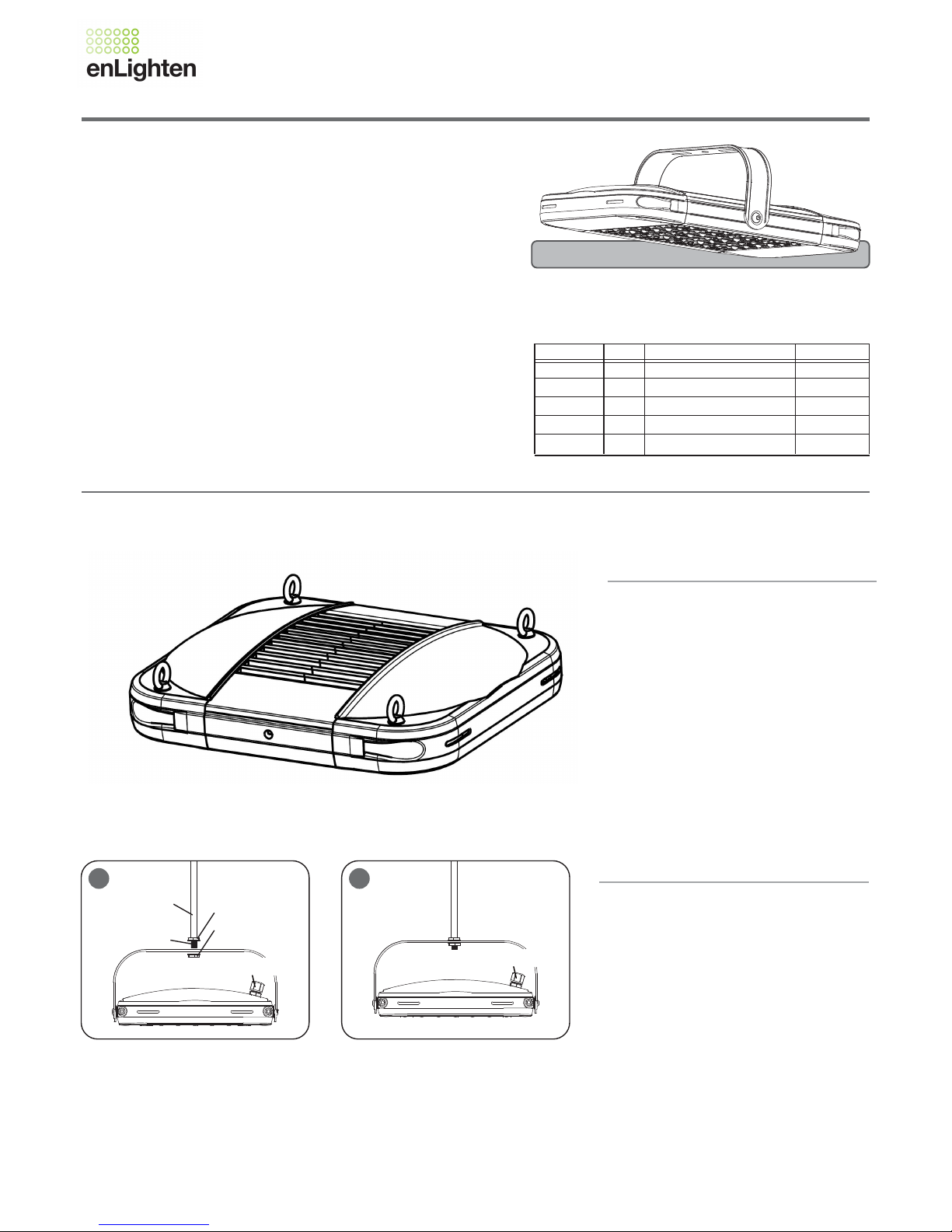
EASY INSTALLATION
Comes with 3m Australian Flex and Plug and eye bolts as standard.
A mouting bracket is available as an optional extra.
READ AND FOLLOW ALL SAFETY INSTRUCTIONS
1.
2.
To avoid the possibility of electrical shock, turn off power supply before
installaon or servicing. Installaon and servicing should be performed
by a qualified electrician and in accordance the latest wiring regulations.
Light must be operated within its specified operating parameters and in
accordance with our warranty requirements.
These documents are available on our website.
TO INSTALL:
Model No.
HB80-5000-xx
HB120-5000-xx
HB160-5000-xx
HB200-5000-xx
HB240-5000-xx
80W
120W
160W
200W
240W
Power
366 x340 x156 mm
439 x340 x156 mm
512 x340 x156 mm
585 x340 x156 mm
658 x340 x156 mm
Dimension
4.3 kg
5.2 kg
6.0 kg
7.0 kg
7.8 kg
Weight
100-240V/277V AC, 50/60Hz, Suitable for Wet Locaons (IP65), Class I
*
This product must be earthed
xx denotes 60° / 90° / 110° degree beam angle
Optional Mounting
Bracket shown
STEP 3:
Connect the power plug to a mains power
socket.
SUSPENSION MOUNTING
STEP 1:
Attach your preferred hanging chain (not
supplied) to the four eye bolts on fitting.
STEP 2:
Secure hanging chain to ceiling.
Use one of the mouting methods described below
STEP 3:
Loosen the mounƟng bracket screws, adjust
the fixture to desired posiƟon, re-secure the
screws.
STEP 4:
Connect the power plug to a mains power
socket.
PENDANT MOUNTING
STEP 1:
Assemble the mounƟng bracket to the fixture
by provided M10 (3/8”) round head screws.
STEP 2:
AƩach Lock-Nut(A) to the boƩom of the
Pendant Stem. AƩach Lock-Nut(B) by holding
the interjacent Fixture Bracket and Ɵghtening
Lock-Nut(B) unƟl secure. See Figure 1.
1 2
Look-Nut(A)*²
Look-Nut(B)*²
Pendant Stem*¹
Pendant Stem Thread
*
¹ Pendant Stem can not be soŌ material (not-provided)
*² Look Nuts are not provided
Power Cord
(Cord Not shown)
Power Cord
(Cord Not shown)
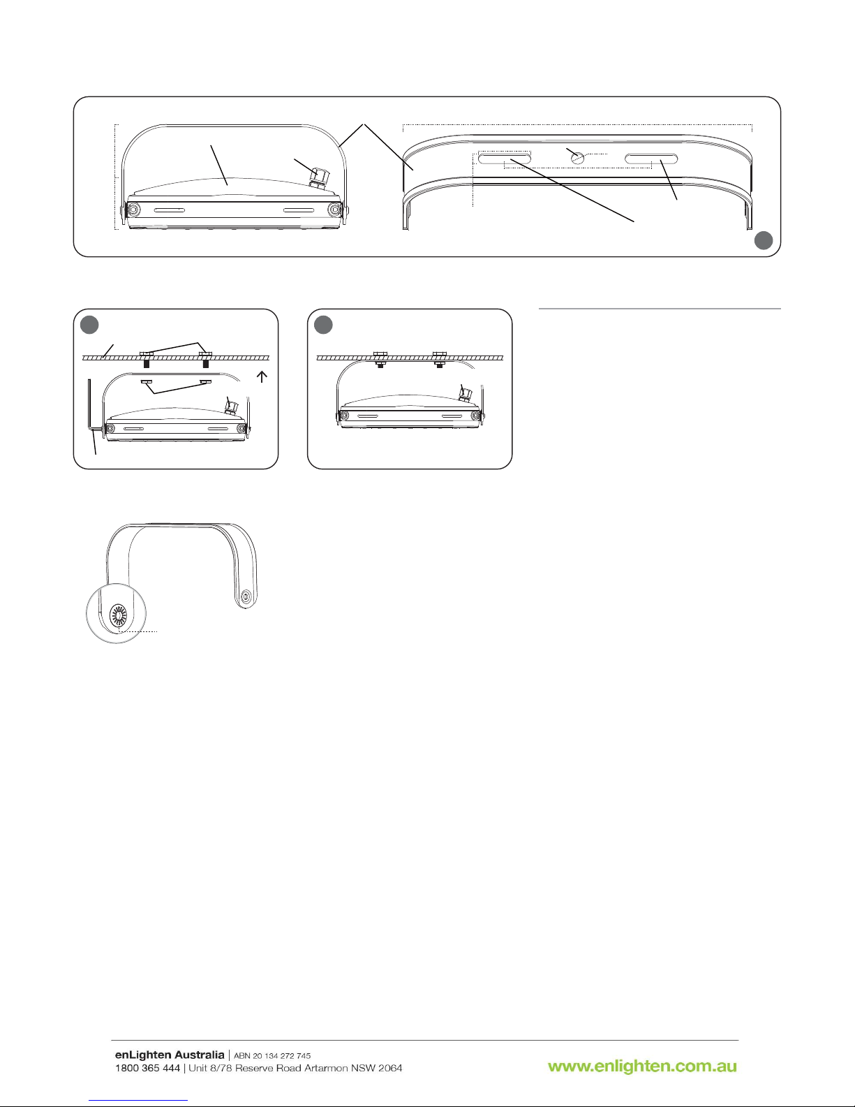
Tighten bracket screws on both sides, luminaire
installaon angle will be fixed by the lock gear.
SURFACE MOUNTING
1
*¹ Minimum M10 (3/8”) Bolts (not-provided)
*² Mounng Nuts are not provided
*³ Allen Wrench: 8mm (5/16”)
2
STEP 1:
Assemble the mounng bracket to the fixture
by provided M10 (3/8”) round head screws.
328 mm (12.91 inches)
40 mm (1.57 inches)
Φ12 mm (0.47 inches)
138 mm (5.43 inches)
12 mm (0.47 inches)
Mounng Bracket
81 mm
(3.19 inches)
75 mm
(2.95 inches)
Luminaire
Mounng Holes For
Minimum M10 (3/8”)
Mounng Bolts
Pendant
Mounng
Hole
Waterproof Connector
1
Celling /Wall
Mounng Bolts*¹
Mounng Nuts*²
Power Cord
(Cord Not shown)
Power Cord
(Cord Not shown)
Allen Wrench*³
STEP 2:
Mount the fixture by TWO(2) minimum M10
(3/8”) bolts. See Figure 1.
STEP 3:
Loosen the mounng bracket screws, adjust
the fixture to desired posion, re-secure the
screws.
STEP 4:
Connect the power plug to a mains power
socket.
 Loading...