


FCC and Industry Canada Compliance Information
Preliminary
This equipment has been tested and found to comply with the limits
for a Class A digital device, pursuant to part 15 of the FCC Rules.
These limits are designed to provide reasonable protection against
harmful interference when the equipment is operated in a
commercial environment. This equipment generates, uses, and can
radiate radio frequency energy and, if not installed and used in
accordance with the instruction manual, may cause harmful
interference to radio communications. Operation of this equipment
in a residential area is likely to cause harmful interference in which
case the user will be required to correct the interfer en c e at his own
expense.
Copyright© 2017 Enlighted Inc. All rights reserved.
All other brand or product names are trademarks of
their respective companies or organizations.
Smart Sensor
(SU-5S)
Installation Instructions
This device complies with Part 15 of t he FCC Rulesand Industry
Canada license-exemptRSS standard(s). Operation is subject to the
following two conditions:
• this device may not cause harmful interference, AND
• this device must accept any interference received, including
interference that may cause undesired operation.
Changes or modificationsnot expressly approved by Enlighted Inc.
could void the user'sauthority to operate the equipment.
Le présent appareil estconforme aux CNR d'Industrie Canada
applicablesaux appareilsradio exempts de licence.L'exploitation
est autorisée aux deux conditions suivantes:
• l'appareil ne doitpas produire de brouillage, ET
• l'utilisateur de l'appareil doit accepter tout brouillage
radioélectrique subi,même si le brouillage est susceptible d'en
compromettre le fonctionnement.
CE
This device complies with the essential requirements and other
relevant requirements of the R&TTE Directive (1999/ 5/EC ) . The
equipment is Class 1 radio equipment which can be placed on the
market and be put into service without restrictions in accordance
with article 1(3) of Commission Decision 2000/299/EC (Version July
2014).
Models:
SU-5S-H: High Bay, Smart Sensor
SU-5S-L: Standard Bay, Smart Sensor
FCC ID: AQQ-SU5S
IC: 10138A-SU5S
Technical Support
For questions regarding the installation or operation of
this product, contact Enlighted
Technical Support: support@enlightedinc.com
Company Contact Information
Location: 930 Benecia Ave, Sunnyvale, CA 94085
Phone: +1.650.964.1094
Web: enlightedinc.com
Smart Sensor (Front a n d Rea r)
Shipped Components
• Smart Sensor
• Anchor Screw
Supplemental Components
• Enlighted Sensor Cable: CBL-2
• Enlighted Control Unit
-7F
Page 5 Page 6
93-02058-01 Rev01
Page 1
Caution
Preliminary
Installationand maintenance must be performed by a qualified
electrician inaccordance with local, state, and nationalelectrical
codes (NEC) and requirements.
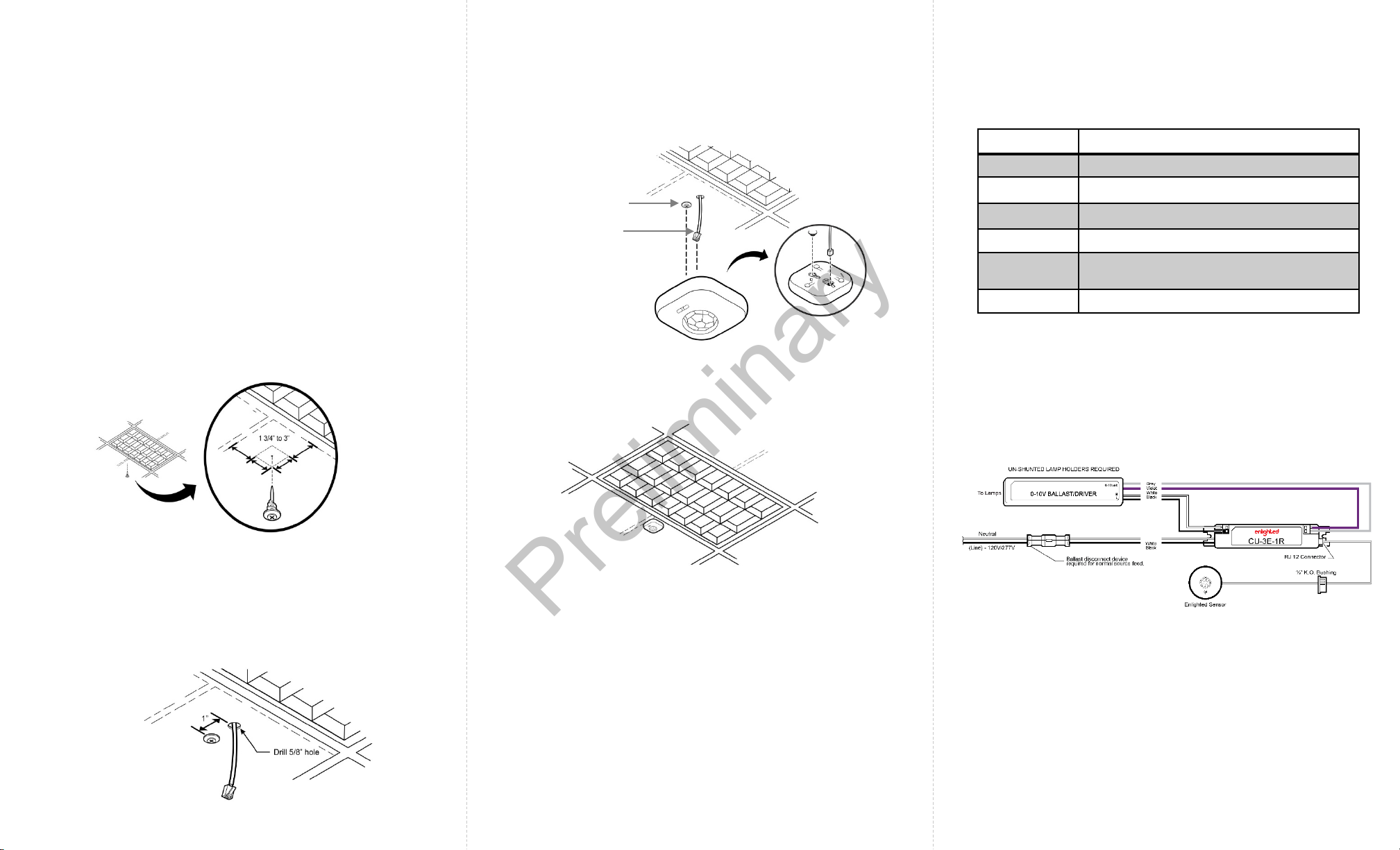
Installation
Step 1: De-energize the luminaire.
The Smart Sensor (SU-5S) should be mounted to the ceiling
tile within a few inches (between 1
fixture.
Step 2: Determine the location of the senso r. Push and
rotate the anchor screw to the tile at that location.
3/4
” to 3”) of the lighting
Step 4: Connect the RJ12 connector to the sensor
bottom.
Anchor Screw
Sensor Cable
LED Description
LED Status Description/Solution
LED not on Check power and wiring
Green blinking Sensor commissioned and working
Red blinking Sensor not commissioned
Red solid Faulty sensor – replace sensor
Green solid Sensor installed, initialized, and uncommissioned
– waiting for discovery.
Blue s o lid Sensor received a request to identify itself
Step 3: Select a place near the anchor screw for the RJ12
connector of the sensor cable from the Control Unit (CU)
to exit. See Wiring Diagram on Page 4.
Make a small cut in the ceiling tile for the cable to exit.
Step 5: Slide the Smart Sensor onto the screw head.
Step 6: Slip the excess sensor cable up into the plenum
area and adjust the ceiling tile to the original position.
Step 7: Energize the luminaire and confirm that the
green LED is solid.
For wiring connections from the Control Unit to the sensor,
refer to the Control Unit Installation Guide.
Wiring Diagram:
Page 2 Page 3 Page 4
 Loading...