

Connecting the Sensor Cable to the Control
Unit
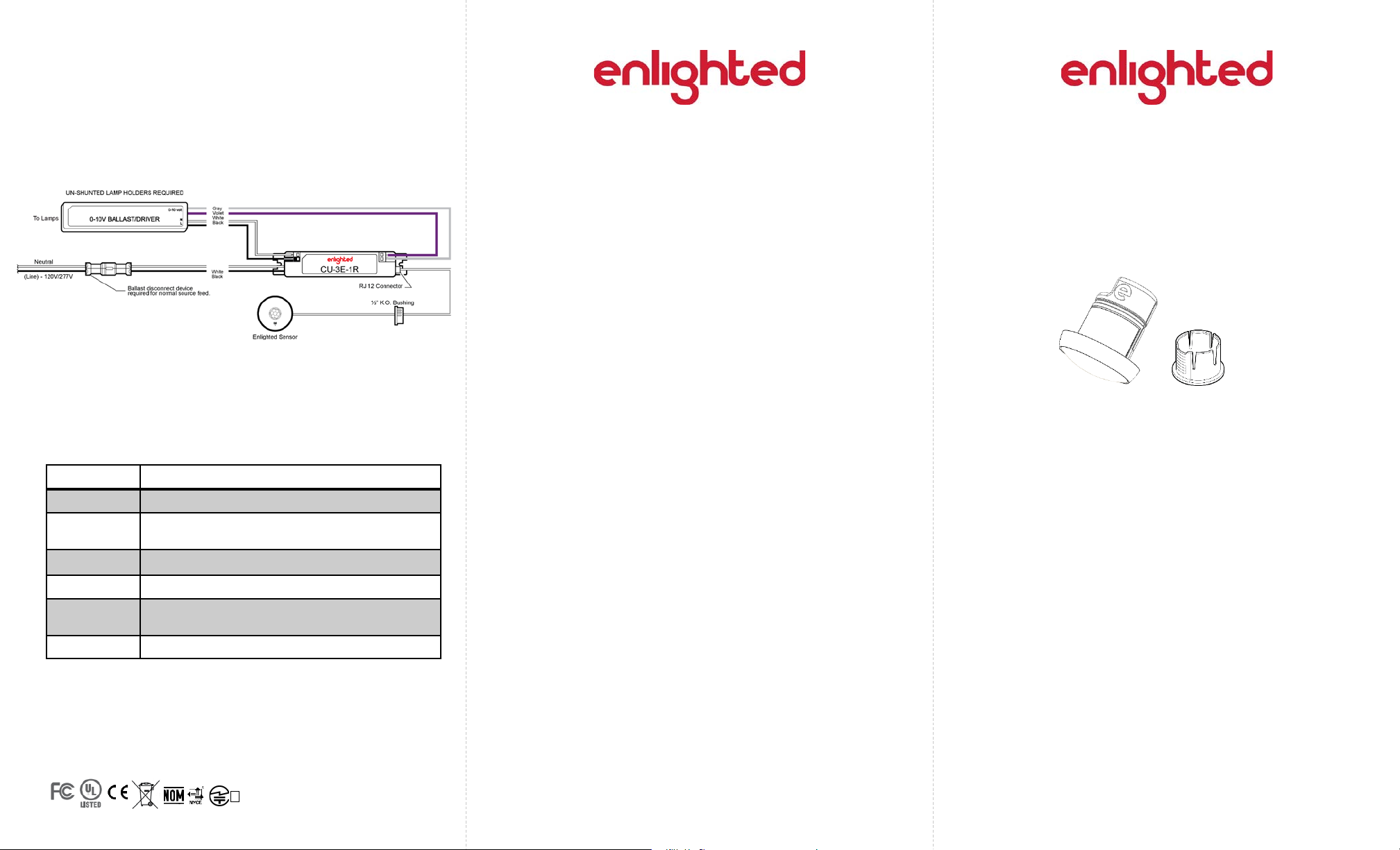
Step 1: Connect the RJ12 end of the sensor cable to the
Control Unit (CU). For wiring connections from the Control
Unit to the sensor, refer to the Control Unit Installation
Guide.
Step 2: Energize the luminaire and confirm that the green
LED is solid.
LED Description
LED Status Description/Solution
LED not on Check power and wiring
Green
blinking
Red blinking Sensor not commissioned
Red solid Faulty sensor – replace sensor
Green solid
Blue s o lid Sensor received a request to identify itself
Model No. : SU-5E-01
FCC ID: AQQ-SU5E
IC: 10138A-SU5E
Sensor commissioned and working
Sensor installed, initialized, and uncommissioned –
waiting for discovery.
R
005-101515
Page 5 Page 6
FCC and Industry Canada Compliance Information
This equipment has been tested and found to comply with the limits for a Class
A digital device, pursuant to part 15 of the FCC Rules. These limits are
designed to provide reasonable protection against harmful interference when
the equipment is operated in a commercial environment. This equipment
generates, uses, and can radiate radio frequency energy and, if not installe d
and used in accordance with the instruction manual, may cause harmful
interference to radio communications. Operation of this equipment in a
residential area is likely to cause harmful interference in which case the user
will be required to correct the interference at his own expense.
This device complies with Part 15 of the FCC Rules and Industry Canada licenseexempt RSS standard(s). Operation is subject to the following two conditions:
• this device may not cause harmful interference, AND
• this device must accept any interference received, including interference
that may cause undesired operation.
Changes or modifications not expressly approved by Enlighted Inc. could
void the user'sauthority to operate the equipment.
Le présent appareil est conforme aux CNR d'Industrie Canada applicables
aux appareilsradio exempts de licence. L'exploitation est autorisée aux
deux conditions suivantes:
• l'appareil ne doit pas produire de brouillage, ET
• l'utilisateur de l'appareil doit accepter tout brouillage radioélectrique subi,
même si le brouillage est susceptible d'en compromettre le
fonctionnement.
CE
This device complies with the essential requirements and other relevant
requirements of the R&TTE Directive (1999/5/EC). The equipment is Class 1 radio
equipment which can be placed on the market and be put into service
without restrictions in accordance with article 1(3) of Commission Decision
2000/299/EC (Version July 2014).
Technical Support
For questions regarding the installation or operation of this
product, contact Enlighted
TechnicalSupport: support@enlightedinc.com
Company Contact Information
Location: 930 Benecia Av e, Sunnyvale, CA 94085
Phone: +1.650.964.1094
Web: enlightedinc.com
Copyright © 2017 Enlighted Inc. All rights reserved.
All other brand or product names are trademarks of
their respective companies or organizations.
Micro Sensor
(SU-5E)
Installation Instructions
Micro Sensor and Carrier
Shipped Components
• Enlighted Micro Sensor
Supplemental Components
• Enlighted Sensor Cable
• Enlighted Control Unit
Tools you may Need
• 7/8” Drill bit (1/2” knock out trade size)
• Hand drill
93-02056-01 Rev02 Page 1
Caution
Installationand maintenance must be performed by a qualified
electrician in accordance with local, state, and nationalelectrical
codes (NEC) and requirements.
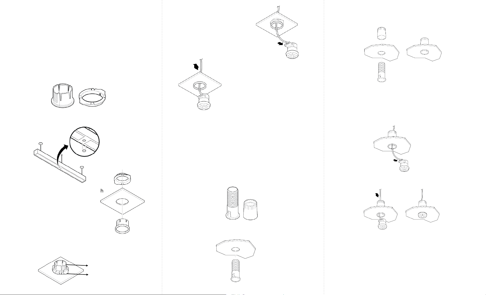
Step 6: Insert the 8-pin end of
the sensor cable through the
carrier.
Step 4: Thread the plain end of the nut from behind the
tile to secure the carrier.
Fixture Mount Sensor Installation
Step 1: De-energize the luminaire.
Note: For fixture mounting, use the fixture carrier and nut
that is shipped with the sensor.
Fixture Carrier
Step 2: Determine the location for the sensor in the
fixture and cut a ½ inch (7/8” diameter) knockout in the
fixture.
Nut
Step 7: Connect the 8-pin
connector to the sensor.
Step 8: Guiding the wire from
above, push the sensor into the
carrier until it securely clicks into
the carrier.
Step 9: Leave four inches of slack
cable in the sequence loop to
avoid pinching of the cable and
to bring the sensor down if it
needs to be replaced.
Note: Do not pull the cable forcefully as this might
damage the cable or connector.
Step 10: See section Connecting the Sensor Cable to the
Control Unit on Page 5.
Tile Mount Sensor Installation
Step 1: De-energize the luminaire.
Note: For tile mounting, use the tile carrier and nut that
is shipped with the sensor.
If the tile is thicker than normal, flip the nut and thread the
ribbed end of the nut to secure the carrier.
Step 5: Insert the 8-pin end of the sensor cable through the
carrier.
Step 6: Connect the 8-pin connector to the sensor.
Step 7: Guiding the wire from above, push the sensor into
the carrier until it securely clicks into the carrier.
Step 3: Insert the fixture carrier through
the hole in the fixture.
Step 4: From behind the fixture, align
the tabs of the nut with the keys on
the fixture carrier.
Step 5: Slide the tabs of the nut along the keys of the
carrier to fasten the carrier.
Keys
Tabs
Page 2
Tile Carrier Nut
Step 2: Make a 7/8
th
diameter hole in the ceiling tile.
Step 3: Insert the tile carrier through the hole into the tile.
Page 3
Step 8: Leave four inches of slack cable in the sequence
loop to avoid pinching of the cable and to bring the
sensor down if it needs to be replaced.
Note: Do not pull the cable forcefully as this might damage
the cable or connector.
Step 9: See section Connecting the Sensor Cable to the
Control Unit on Page 5.
Page 4
 Loading...