

Page 1
EN-KO Electronic Control Systems AMF 4.0/ENG/K.K./02
1
AMF 4.0 AUTOMATIC MAINS FAILURE UNIT
USER MANUAL
V1.36
(AMF 4.0 version 25)
GEN
I
T
Battery
Temp
I
S
I
R
Oil press
TEMPERATURE LEVEL
OIL LEVEL
Critical
Level
Max.
Level
100
0
C50 0 C
AUX.
AMF 4.0
Automatic Mains Failure
122 0 F
212
0
F
Engine
hour
Freq
V
R
V
S
V
T
MAINS
G
START
A
TEST
V
V
RS
V
ST
V
TR
Esc
EscEsc
Esc
MENU
OFF
STOP
I / 0 I / 0
DESCRIPTION
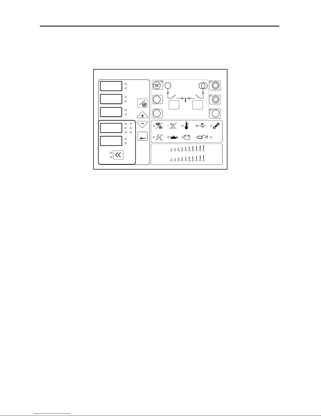
AMF 4.0 genset control unit provides the functions, required in automatic mains failure
applications of gensets. It can be operated in automatic, test and manual modes. It contains
digital displays providing functions of all analog displays needed in generator panels. Device
digital displays show 3 phase mains and generator voltages, 3 phase generator currents, mains
and generator frequencies, battery voltage, oil pressure (bar), engine temperature and engine
hour. Generator is monitored constantly and when generator or mains values exceed the limits
adjusted in the parameter menu, necessary actions are taken and alarm is activated. Last ten
alarms are recorded in the device memory. All operating modes and timings can be adjusted
in the parameter menu. This flexibility is provided for different kinds of generator
applications.
FUNCTIONS
• Manual engine starting and stopping
• Mains monitoring, automatic start, stop and transfer switch functions
• True RMS voltage and current measurements
• Failures monitoring
• Preheating
• Manuel, automatic and test modes
• Cost effective digital measurement displays
• Recording of last 10 failure
• Engine hour measurement and periodic service time warning
• Manuel and automatic control of mains and generator contactors
• Analog engine temperature and oil pressure measurement capability
• Adjustable operating modes and timings via parameter menu
• Analog bar graph, engine temperature and oil pressure displays
• Adjustable measurement calibrations
• Remote Start
Page 2
EN-KO Electronic Control Systems AMF 4.0/ENG/K.K./02
2
INPUT / OUTPUTS
• 3 phase mains and generator voltage inputs
• 3 phase generator current inputs
• 12 or 24 V battery supply input
• Oil pressure and temperature analog inputs
• Charge alternator input
• Cranking relay output
• Preheat relay output
• Fuel solenoid relay output
• Mains contactor relay output
• Generator contactor relay output
• Alarm relay output
• 2 programmable auxiliary relay output
• 2 programmable auxiliary input
ALARMS
• Engine start/stop failure
• Under/over speed failure
• Under/over voltage failure
• Over current failure
• High temperature failure
• Charge fail warning
• Low oil pressure failure
• Periodic service time warning
• Auxiliary failure
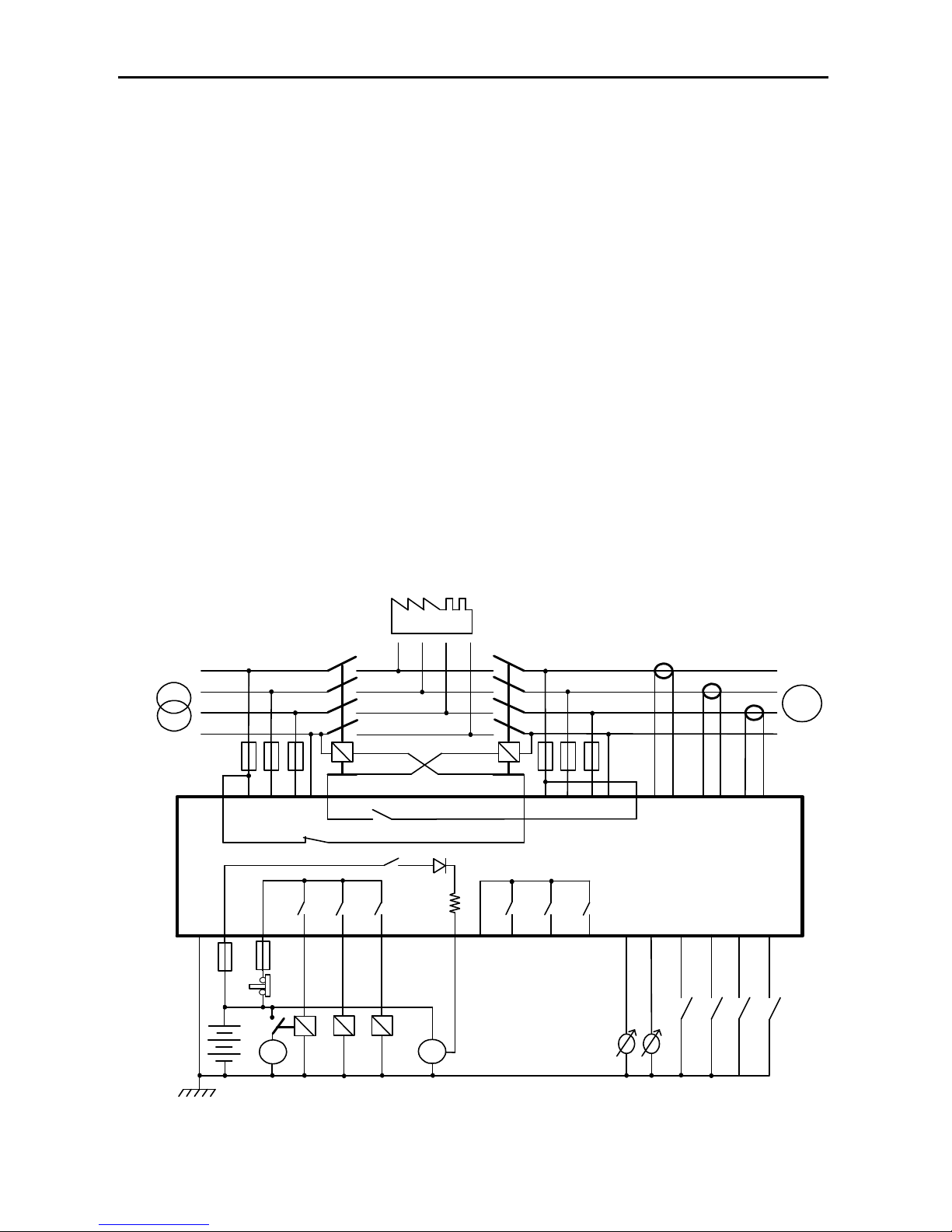
AMF 4.0 CONNECTION DIAGRAM
AMF 4.0
Generator Contactor
Relay
Mains Contactor Relay
G
R
S
T
N
U
V
W
N
LOAD
R S
T N
GENERATORMAINS
12
23
19
18
17
22
11 14
353433
32
31
30
2928
27
26
25
24
Configurable Input 1
(Default Oil Pressure Switch)
Configurable Input 3
Battery
1
2
Oil Pressure sender
Temperature Sender
Crank
Charge
Fuel Selenoid
Preheating Ralay
3
5 212010
98
7
15
6
4
Configurable output 1
(Default Horn)
D+WL
Power Supply
Crank Relay
13
Emergency
Stop
Com 2
16
Configurable Input 4
Generator Current
Inputs
Configurable output 2
Configurable output 3
Configurable Input 2
(Default Temperature Sw itch)
NEGATIVE TERMINAL OF BATTERY
SHOULD BE GROUNDED
Page 3
EN-KO Electronic Control Systems AMF 4.0/ENG/K.K./02
3
FRONT PANEL
GEN
I
T
Battery
Temp
I
S
I
R
Oil press
TEMPERATURE LEVEL
OIL LEVEL
Critical
Level
Max.
Level
100
0
C50 0 C
AUX.
AMF 4.0
Automatic Mains Failure
122 0 F
212
0
F
Engine
hour
Freq
V
R
V
S
V
T
MAINS
G
START
A
TEST
V
V
RS
V
S T
V
T R
Esc
EscEsc
Esc
MENU
OFF
STOP
I / 0 I / 0
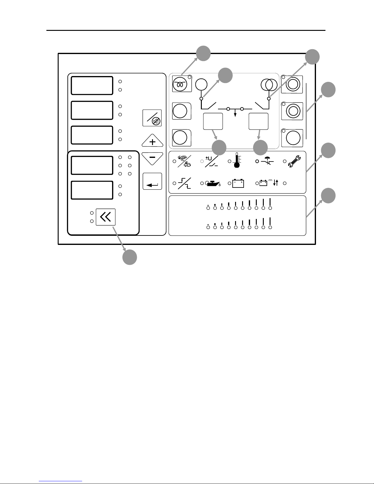
PreHeat Button (1): When genset doesn’t start in cold weathers, engine can be preheated
with this button. Button function can be set as “button must be held down to preheat” or
“preset preheat time when you press button”. Preheat button can be used in manual mode and
when engine is not running.
Start Button: This button is used to start genset . Panel will stop cranking when it detects
engine running signals. Button function can be set as “button must be held down to crank” or
“preset cranking time when you press button”. Start button can be used in manual mode and
when engine is not running. Panel will display “Str” message during cranking.
Stop Button: This button is used to stop the genset. When you pressed this button first time
panel switched to manual mode and if generator contactor is used before, genset is switched
to cooling mode. If you pressed second time genset stops immediately. Second function of
this button when you press more than 3 seconds panel will switch to off mode.
Generator Contactor (2): This button is used to transfer load to genset. When genset is
running this button can be used. Led lamp above the button shows contactor status. When the
led lamp is lit, contactor is closed. Generator contactor cannot be closed when the mains
contactor is closed. To close generator contactor, you must open the mains contactor first. In
engine running condition, when you press stop button, generator contactor will open
immediately.
9
7
6
8
1
2 3
4
5
Page 4

EN-KO Electronic Control Systems AMF 4.0/ENG/K.K./02
4
Mains Contactor (3): This button is used to control mains contactor. It cannot be closed if
generator contactor is closed.
Generator Status Led Lamp (4):
• It is off, if engine isn’t running.
• It is on, if engine is running
• It is blinking, if genset is in engine stabilization, cooling or stopping. These topics will
be explained later
Mains Status Led Lamp (5):
• It is off, if mains voltage is outside the limits of preset values.
• It is on, if mains voltage is inside the limits of preset values.
• It is blinking in transition times (mains failure delay and mains return delay) if mains
change the state from normal to failure or failure to normal state
Alarm Led Lamps (6): From the upper left corner, high and low generator speed, high and
low generator voltage, high coolant temperature, over current and service alarms. From lower
left corner start and stop failure, low oil pressure, charge failure, battery voltage failure and
auxiliary alarms. Detailed description will be given in the following chapters.
Oil Pressure and Coolant Temperature bar graphs (7): Analog oil pressure and coolant
temperatures can be seen in bar graphs. In temperature bar graph temperature can be seen
from 50° C/ 112 °F to 100 °C/212 °F. In oil press bar graph, oil press can be seen from oil
pressure failure level to maximum oil press sender level.
Display Leds: These leds are in the right side of numerical displays. Leds indicates meaning
of the value in the displays. Values in the displays can be changed by up, down and menu
buttons.
Measuring Mode Button (8): The button selects the displayed values at lower 2 numerical
display. These displays can show generator voltage and frequency or mains voltage and
frequency.
Esc Button: This button has multiple tasks. These are listed below,
• In alarm condition, first press stops the horn and second press clears the alarm.
• It is used to exit parameter menu. For this process button must be held down 3
seconds.
• In the process of changing parameter when you enter invalid values you can cancel by
this button.
Menu Button (Enter): This button has multiple tasks. These are listed below
• It is used to select the values in the numerical displays. When you press first time led
will be lit on the right of the display that is in selection mode. If you press up and
down buttons before stop blinking you can change the value shown in display. If the
display that is wanted to change mode is different you can press menu button and
change the display in selection mode.
• If you press this button 3 seconds, you will enter the parameter menu. In parameter
menu you can use menu button to change selected parameter. You can change the
active digit. After all active digits are set last press will write value to parameter
memory. Detailed information will be given in parameters section.
Page 5
EN-KO Electronic Control Systems AMF 4.0/ENG/K.K./02
5
Up, Down Buttons (+, -): This button has two tasks. These are listed below.
• It is used to select the values in the numerical displays. When you press first time led
will be lit on the right of the display that is in selection mode. If you press second time
you can change the value of display that is in selection mode.
• In parameter menu you can press menu button to change selected parameter. You can
change the number of active digit.
Running Mode Buttons (9): These are manual (hand mark), automatic (A letter) and test
buttons. These buttons set running mode of genset. There is mode indication leds near each of
these buttons. When panel is in off mode you can press these buttons to wake up panel and
genset will run in selected mode.
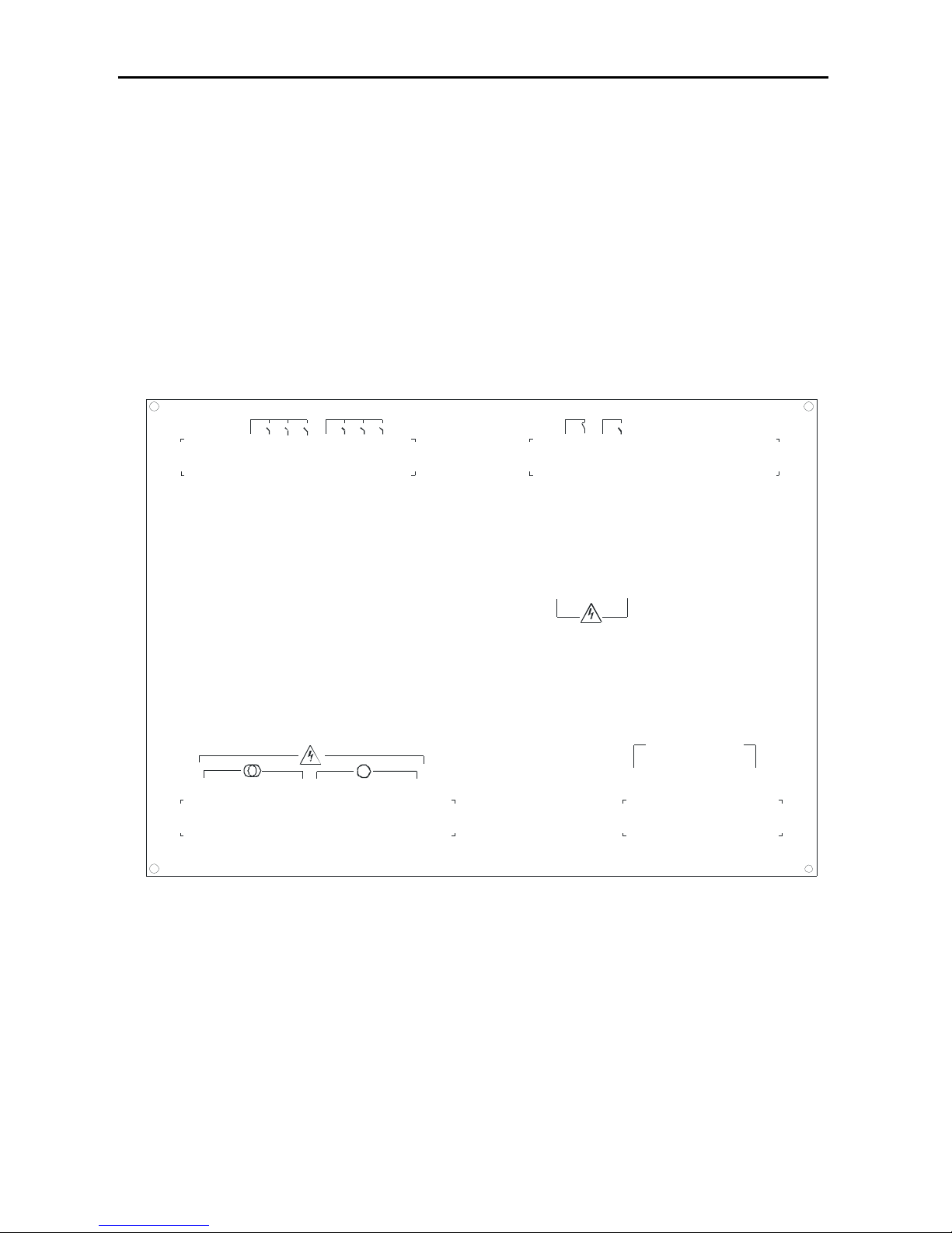
REAR CONNECTIONS
I
T
+
I
S
+
I
R
+
I
R
-
I
T
-
I
S
-
30 31 32 33 34 35
22 23 24 25 26 27 28 29
G
11 12 13 14 15 16 17 18 19 20 21
CRANKING
COM 1
BATT (+)
COM 2
BATT (-)
AUX. OUTPUT 2
FUEL SELENOID
AUX. OUTPUT 1
AUX. OUTPUT 3
PREHEAT
1 2 3 4 5 6 7 8 9 10
MAINS CONT. COM.
AUX. INPUT 3
OIL PRESSURE
AUX. INPUT 2
AUX. INPUT 4
TEMPERATURE
MAINS CONT. NC
GEN CONT. COM.
GEN. CONT. NO
CHARGE FAIL-EXCIT.AUX. INPUT 1
N
W
V
U
N
T
S
R
CURRENT
TRANSF ORMER
INPUTS
Page 6
EN-KO Electronic Control Systems AMF 4.0/ENG/K.K./02
6
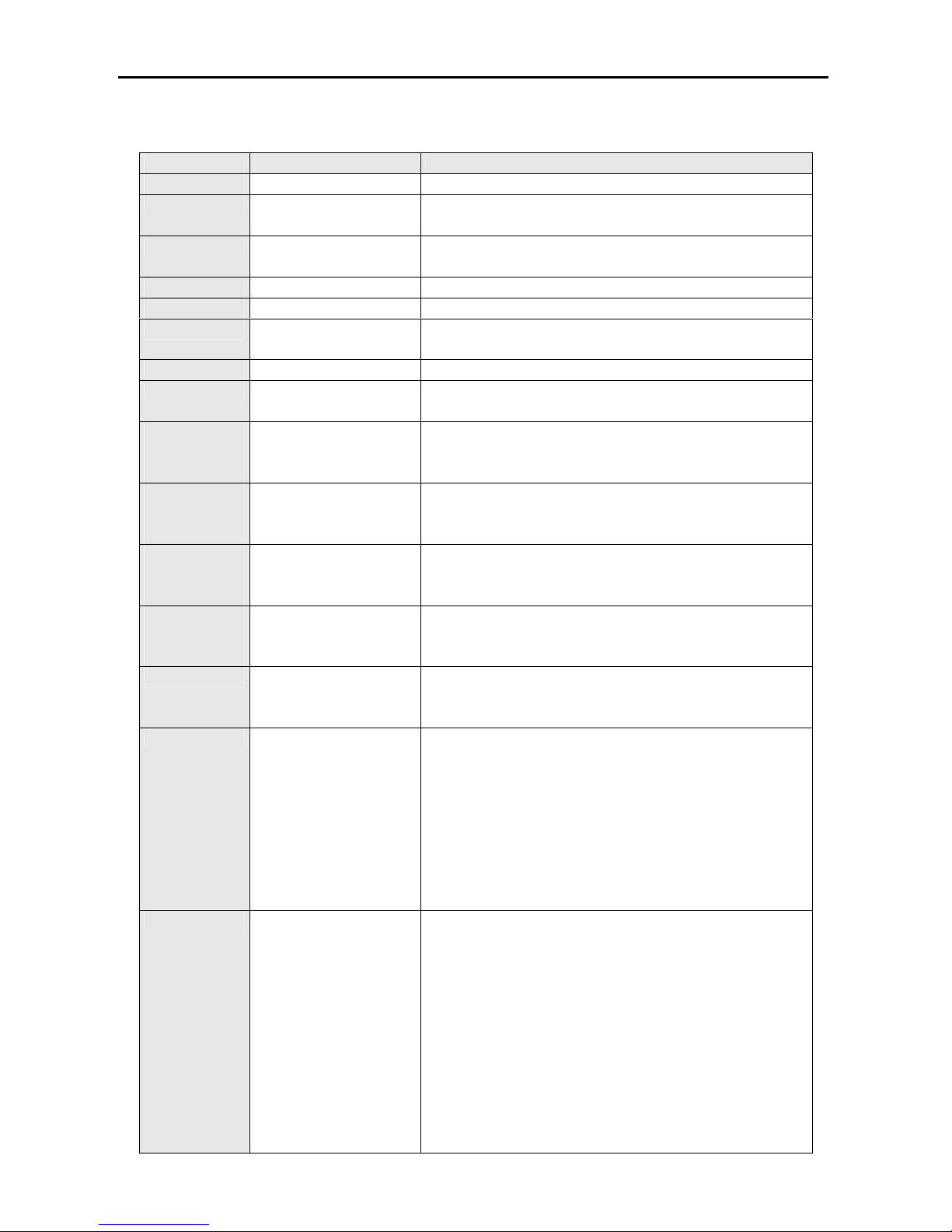
CONNECTIONS
Terminal No
Terminal Name Description
1
Bat (+) Battery positive. Voltage must be between 9- 30 V
2
Bat (-) Battery negative. Battery negative must be connected
to earth.
3
Com 1 Common terminal of preheat, fuel solenoid and
cranking relays.
4
Preheat Preheat relay
5
Cranking Cranking relay
6
Fuel Solenoid Fuel or stop solenoid relay. Operating mode must be
selected from parameter menu.
7
Com 2 Common terminal of auxiliary relay 1, 2, 3
8,9,10
Aux. Output 1, 2, 3 Multiple function auxiliary relay outputs. Auxiliary
output 1 is default horn output.
11
HIGH
VOLTAGE
Mains Cont. Com.
Input terminal of mains contactor relay. Line R of
mains can be connected to this terminal
12
HIGH
VOLTAGE
Mains Cont. NC Output terminal of mains contactor relay. This output
is connected to mains contactor.
13
HIGH
VOLTAGE
Gen Cont. Com. Input terminal of generator contactor relay. Line U of
generator can be connected to this terminal
14
HIGH
VOLTAGE
Gen Cont. NO
Output terminal of generator contactor relay. This
output is connected to generator contactor.
15
Charge Fail Excit.
Warning lamp output of charge alternator must be
connected here. In the cranking excitation current is
supplied to charge alternator over 150 ohm resistor.
16
Aux. Input 1
Multiple function auxiliary input. These inputs are
activated if it is connected to battery negative. If oil
sender that have both sender and switch function is
used, switch terminal must be connected to this
terminal. Suitable configuration must be set for this
input to use it as oil pressure switch input. If this
input is used for auxiliary input. Alarm will be shown
as A1 in the display at the same time with auxiliary
led indication.
17
Aux. Input 2
Multiple function auxiliary input. These inputs are
activated if it is connected to battery negative. If
temperature sender that have both sender and switch
function is used, switch terminal must be connected to
this terminal. Suitable configuration must be set for
this input to use it as temperature switch input. If this
input is used for auxiliary input. Alarm will be shown
as A2 in the display at the same time with auxiliary
led indication.
Page 7
EN-KO Electronic Control Systems AMF 4.0/ENG/K.K./02
7
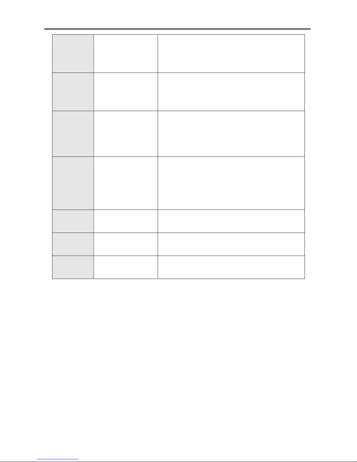
18
Aux. Input 3
Multiple function auxiliary input. These inputs are
activated if it is connected to battery negative. If this
input is used for auxiliary input. Alarm will be shown
as A3 in the display at the same time with auxiliary
led indication.
19
Aux. Input 4
Multiple function auxiliary input. These inputs are
activated if it is connected to battery negative. If this
input is used for auxiliary input. Alarm will be shown
as A4 in the display at the same time with auxiliary
led indication.
20
Oil Pressure If oil sender that have both sender and switch function
is used, sender terminal must be connected to this
terminal. If oil sender that has single oil pressure
switch output, switch output must be connected to this
input. Suitable configuration must be set for this input
to use it as oil pressure switch or sender input.
21
Temperature If temperature sender that have both sender and
switch function is used, sender terminal must be
connected to this terminal. If temperature sender that
has single temperature switch output, switch output
must be connected to this input. Suitable
configuration must be set for this input to use it as
temperature switch or sender input.
22,23,24,25
HIGH
VOLTAGE
Mains Line and
Neutral Inputs
Mains line and neutral are connected to these
terminals.
26,27,28,29
HIGH
VOLTAGE
Generator Line and
Neutral Inputs
Generator line and neutral are connected to these
terminals.
30,31,32,33
34, 35
Current Transformer
Inputs
Secondary side of current transformer must be
connected here. Each transformer must be connected
separately.
Note: Battery negative must be connected to earth
RUNNING MODES
Automatic Mode: If you press automatic button marked “A” genset will switch to automatic
mode. In this mode panel controls mains voltages and if mains is outside the limits that you
programmed, Panel will open the mains contactor and starts the genset. After “engine
stabilization time” and “generator contactor delay” load transferred to the generator. Panel
controls all the engine values to detect possible failures after engine stabilization time. If
mains come to normal condition, mains is controlled during “mains return delay” for
stabilization. If mains is normal “after mains return delay”, generator contactor opens and
mains contactor closes. Genset is stopped after cooling period. In automatic mode, if panel is
in engine off state and detects an engine running signal. Panel will stop the engine.
Test Mode: If you press test button at the right side of front panel. Genset will be switched to
test mode. In test mode engine starts immediately. After “engine stabilization time” if
parameter”test mode” is test off load genset wait for mains failure in running condition. When
mains failure occur mains contactor opens and generator contactor closes. In same way when
mains returns, panel waits”mains return delay” and switch back to mains. If parameter “test
mode” is test on load. After engine starting, generator contactor closes and genset supply the
Page 8

EN-KO Electronic Control Systems AMF 4.0/ENG/K.K./02
8
load. If operator wants to stop the engine in test mode panel must be returned to automatic or
manual mode. In manual mode you can stop the engine by stop button.
Manual Mode: If you press the manual button genset will be switched to manual mode. In
manual mode all start stop and preheat operations, contactor control fulfilled by panel buttons.
PANEL RUNNING PHASES
1. Generator is still: In this condition engine running signals must be absent. These are oil
pressure, charging alternator warning lamp signal, generator voltage and frequency. In
manual mode panel doesn’t react to this signal but in automatic mode panel will try to
stop engine. If electricity panel of genset has manual control and these are wanted to be
used. Electronic panel must be switched to manual mode.
2. Preheating: In cold weathers preheating of engine can be necessary. Engine must be still
during preheating. If parameter “preheating time” is not zero, preheating is accomplished
before starting process by panel.
3. Cranking: In this stage engine is cranking. All engine signals must be absent and engine
must be still before cranking. If one of the engine signal is detected before cranking, panel
switch to start and stop alarm. Panel will show which signal is detected with engine start
stop alarm. If oil pressure signal is detected before cranking panel will wait for it to
decrease to zero. If “before cranking oil pressure delay” is elapsed and oil pressure is not
zero panel will switch to start and stop alarm. In cranking stage all engine signals,
alternator frequency, alternator voltage, charge alternator voltage and oil pressure is
controlled. If one of the signals is detected, Panel detects engine is running, crank
disconnects and switch to engine stabilization time. Generator status led starts to blink.
During cranking, “Str” message is shown in the display. Oil pressure can rise before
engine running so when oil pressure is detected, crank disconnected after “crank
disconnect oil pressure delay”.
4. Stabilization: After generator running signals detected panel waits for engine signals to
stabilize. After engine stabilization time, all alarms are activated.
5. Running: After stabilization time genset is in running condition. If genset in manual and
test modes, alternator contactor time is waited and alternator contactor is closed. In
manual mode operator can close the generator contactor by generator contactor button. In
running mode generator status led is lit.
6. Cooling: If a stop condition occurs by operator or mains status. Generator is switched to
cooling period and engine is cooled during “cooling time”. During this time engine status
led is blinking. If alternator contactor hasn’t been closed since last start cooling period is
bypassed. If mains failure occurs during cooling process generator is switched back to
running mode and alternator contactor is closed. After cooling process generator is
switched to stopping condition.
7. Stopping: After cooling stage, generator switches to stopping stage. If fueling system is
operating solenoid, operating solenoid is de-energized. If fueling system is stop solenoid
solenoid energizes until engine stops. If one of the engine running signals is detected
stopping period doesn’t ends. Alternator frequency and voltage, charge alternator warning
lamp signal and oil pressure must be absent. If panel detects engine signals after “fail to
stop delay” panel will switch to start stop alarm.
8. Generator shutdown: Generator is stopped because of a red alarm. Generator cannot be
started if alarm is not cleared.
Page 9
EN-KO Electronic Control Systems AMF 4.0/ENG/K.K./02
9
ALARMS
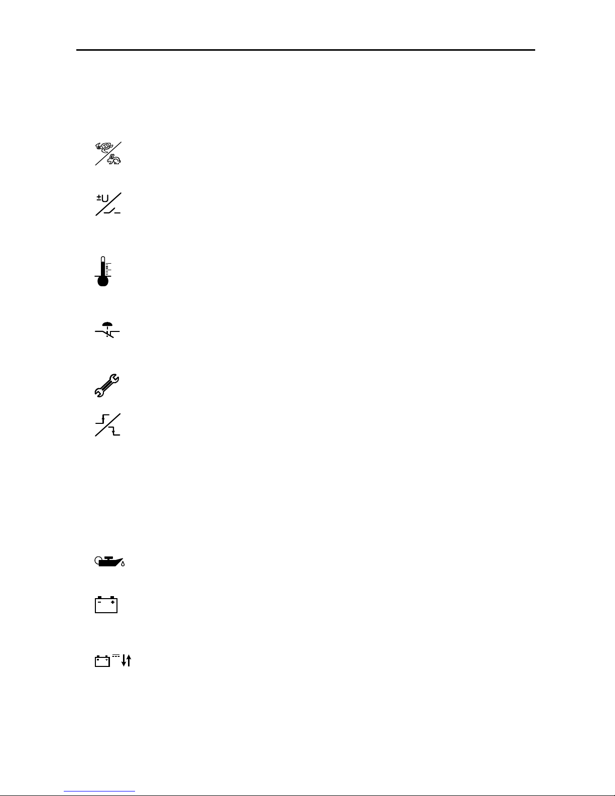
Alarms are divided to red and yellow alarms. Yellow alarms are for warning purposes and
don’t stop the generator. Red alarms are serious and if occur generator contactor is opened
and generator is stopped immediately.
High and low speed (RED ALARM): If alternator frequency is higher than
“generator over frequency failure” or is lower than “generator under frequency
failure” “panel switches to this alarm. Alarm is activated after “generator
frequency failure delay”.
High and low alternator voltage (RED ALARM): If alternator voltage is higher
than “generator over voltage failure” or is lower than “generator under voltage
failure” “panel switches to this alarm. Alarm is activated after “generator voltage
failure delay”
High coolant temperature (RED ALARM): If temperature that is read from
temperature sender is higher than “high coolant temperature level” or if
temperature switch sends alarm to panel. Panel switches to high coolant
temperature alarm.
Over current failure (RED ALARM): If currents values read from current
transformers is higher than “over current level”. Generator contactor is opened and
generator switches to cooling. After cooling stage generator stops. Alarm is
activated if condition continues for “over current alarm delay”
Periodic service:
When periodic service time elapsed after last periodic service.
Alarm is displayed. Only service personnel can reset alarm.
Fail to start stop: If this alarm occurs that means panel couldn’t start or stop
engine. All engine signals must be absent and engine must be still before cranking.
If one of the engine signals is detected, before cranking, panel switch to start and
stop alarm. Panel will show which signal is detected with engine start stop alarm.
If oil pressure signal is detected before cranking panel will wait for it to decrease
to zero. If “before cranking oil pressure delay” is elapsed and oil pressure is not
zero panel will switch to start and stop alarm. In automatic and test modes if
generator couldn’t be started after user defined crank attempts, panel switches to
fail to start stop alarm. In engine stopping stage if panel still detects engine signals
after “fail to stop delay”. Panel switches to fail to start stop alarm. Alarm led lamps
indicates which engine signal is still present and causes fail to start stop alarm.
Low oil pressure (RED ALARM): If oil pressure that is read from oil pressure
sender is lower than “low oil pressure level” or if oil pressure switch sends alarm
to panel. Panel switches to low oil pressure alarm.
Charge Failure (YELLOW ALARM): If charge voltage read from charge
alternator warning lamb terminal decreases, panel switches to this alarm. This
alarm doesn’t stop generator.
V
Battery high and low voltage (YELLOW ALARM): If battery voltage is higher
than “battery high alarm level” or is lower than “battery low alarm level” panel
switches to this alarm. This alarm doesn’t stops engine.
AUX.
Auxiliary input (YELLOW or RED ALARM): When an auxiliary input alarm
occur. This led is lit and A1, A2, A3 or A4 message is written to display. A1
means auxiliary input1 alarm.
Page 10

EN-KO Electronic Control Systems AMF 4.0/ENG/K.K./02
10
Mains failure: If mains voltage is lower than “mains under voltage failure” or is
higher than “mains over voltage failure” mains failure occur and in automatic
mode generator is started. If mains comes to normal condition (higher than “under
voltage return” and lower than “over voltage return”) generator is stopped in
automatic condition.
Emergency stop: If auxiliary input is adjusted for emergency stop and user
presses emergency stop button. “StP” message is shown in the display, generator
contactor opens and engine stops immediately. To clear this alarm user must pull
emergency stop button and clear the alarm.
Sensor failure: If cable connected to sender terminal of oil pressure and
temperature senders breaks. Sensor failure alarm is given. For oil pressure sender
“oSn” message and for coolant temperature sender “tSn” message is shown in the
display. Alarm is activated if condition continues for 4 seconds. If “analog oil
pressure sender usage” and “analog coolant temperature sender usage” parameters
are set to 0, sender will be used for display purposes and no alarm is given in
sensor failure condition.
EEProm Failure: When this alarm occurs “EEP” message is written to display
and you must call service. Genset mustn’t be started.
PARAMETER MENU
To enter parameter menu, menu button must held down for 3 seconds. Password screen is
displayed. Parameter menu contains 3 separate sections. These are operator, technician and
calibration parameters sections. You can give separate password to these sections and enter to
these sections by its passwords. In parameter section leftmost digit starts to blink. If you press
up and down buttons you can increase and decrease the value shown in the blinking digit. If
you want to proceed to digit at one-step right menu button must be pressed. You can adjust
this digit up and down buttons and then you press menu button again. If you are in the
rightmost digit and you have adjusted this digit, you can complete password entering by
pressing menu button. You can exit menu by holding esc button for 3 second. When you enter
the parameter menu at the first row of display “P0” (first parameter number) is shown. At the
second row of display value of parameters is shown. If you want to proceed to other
parameters you can use up and down buttons (P0, P1, P2…). Maximum parameter number is
depends on your entered password (operator, technician or calibration). If you want to change
parameter, menu button must be pressed at the selected parameter. At the third row parameter
value is displayed and first digit of value blinks. Changing process is same as password
entering process. By pressing menu button at last blinking digit new value is recorded. If you
want cancel entering process you can press esc key. In return to factory defaults parameters
when you press menu button NO message displayed if you press up and down buttons
message will switch to YES and NO messages if you press menu button, when selection is
YES, parameters will be returned to factory defaults. If you press NO process is cancelled.
Each return to factory defaults, return its own section to factory defaults (operator, technician,
calibration). If you want exit menu you can press down esc button for 3 second.
Page 11
EN-KO Electronic Control Systems AMF 4.0/ENG/K.K./02
11
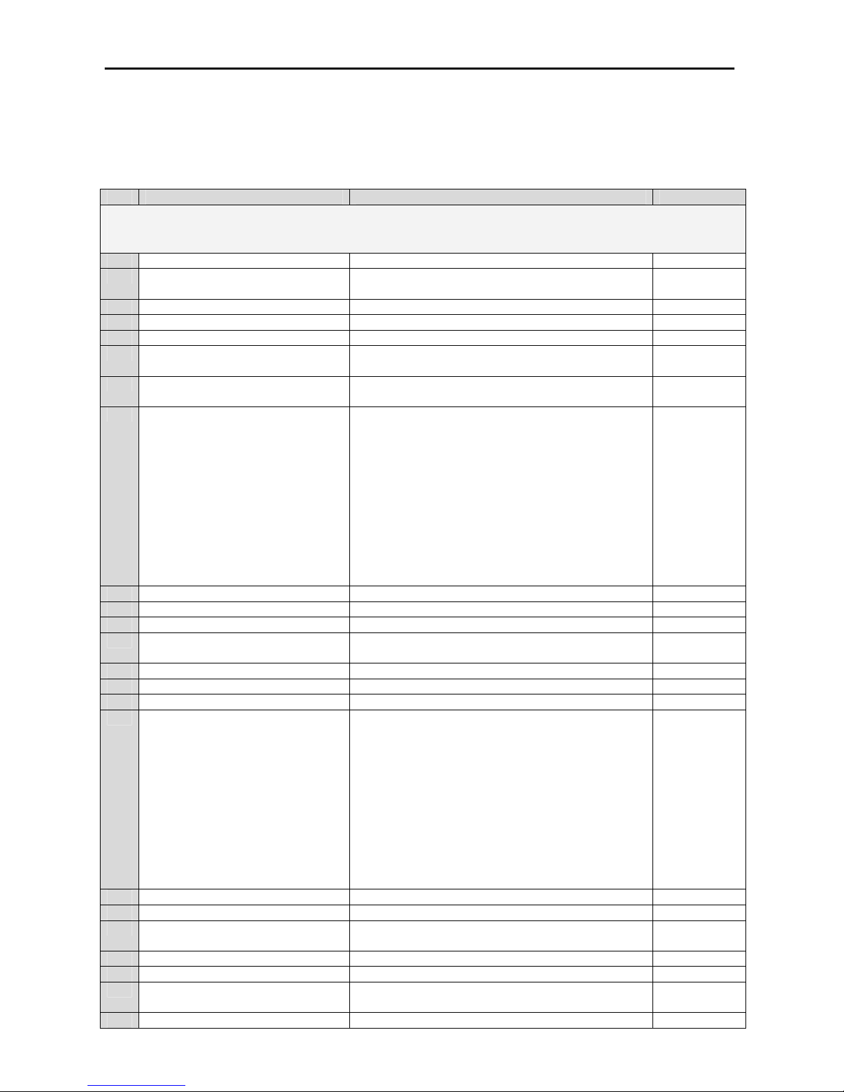
AMF 4.0 PARAMETERS
Initial parameter settings are for genset model 10. These are as following table. For chosen
genset model, parameter table can be loaded by means of parameter 69. Parameters that is
changed according to genset models are specified in the next sections.
No Parameter Setting Range Default Value
Operator Parameters
P0 Operator menu password 0-999 050
P1 Temperature unit 0: Celsius
1: Fahrenheit
0
P2 Crank attempts 1 – 9 3
P3 Cranking time 1-60 sec 10 sec
P4 Cranking pause time 3-60 sec 10 sec
P5 Manuel cranking type 0: Start button must be held down to crank
1: Automatic start
0
P6 Preheating type 0:Preheat button must be hold down to preheat
1: Automatic preheat
0
P7 Auxiliary input 1 function 0: Input disabled
1: Yellow alarm (always active)
2: Yellow alarm (active from starting)
3: Yellow alarm (active form engine stabilization time)
4: Red alarm (always active)
5: Red alarm (active from starting)
6: Red alarm (active from engine stabilization time)
7: Remote start
8: Remote main failure disable
9: Mains available
10: Emergency stop
11: Cabinet thermostat alarm
6
P8 Auxiliary input 2 function Same as auxiliary input 1 0
P9 Auxiliary input 3 function Same as auxiliary input 1 10
P10 Auxiliary input 4 function Same as auxiliary input 1 4
P11 Auxiliary input 1 activation method 0: Close to activate
1: Open to activate
0
P12 Auxiliary input 2 activation method Same as auxiliary input 1 0
P13 Auxiliary input 3 activation method Same as auxiliary input 1 0
P14 Auxiliary input 4 activation method Same as auxiliary input 1 0
P15 Auxiliary output 1 function 0: Output disabled
1: Engine running
2: Panel is in auto or test mode
3: Yellow alarm
4: Red alarm
5: Common alarm
6: Horn
7: Panel is in manual, auto or test mode
8: Panel is in auto mode
9: 6 sec stop output during engine stop
10: Fuel solenoid output
11: Auxiliary services
0
P16 Auxiliary output 2 function Same as auxiliary output 1 0
P17 Auxiliary output 3 function Same as auxiliary output 1 0
P18 Auxiliary output 1 activation method 0: De-Energize
1: Energize
1
P19 Auxiliary output 2 activation method Same as auxiliary output 1 1
P20 Auxiliary output 3 activation method Same as auxiliary output 1 1
P21 Test Mode 0: Test off load
1: Test on load
0
P22 Max. Stop solenoid working time 1-180 sec 6 sec
Page 12
EN-KO Electronic Control Systems AMF 4.0/ENG/K.K./02
12
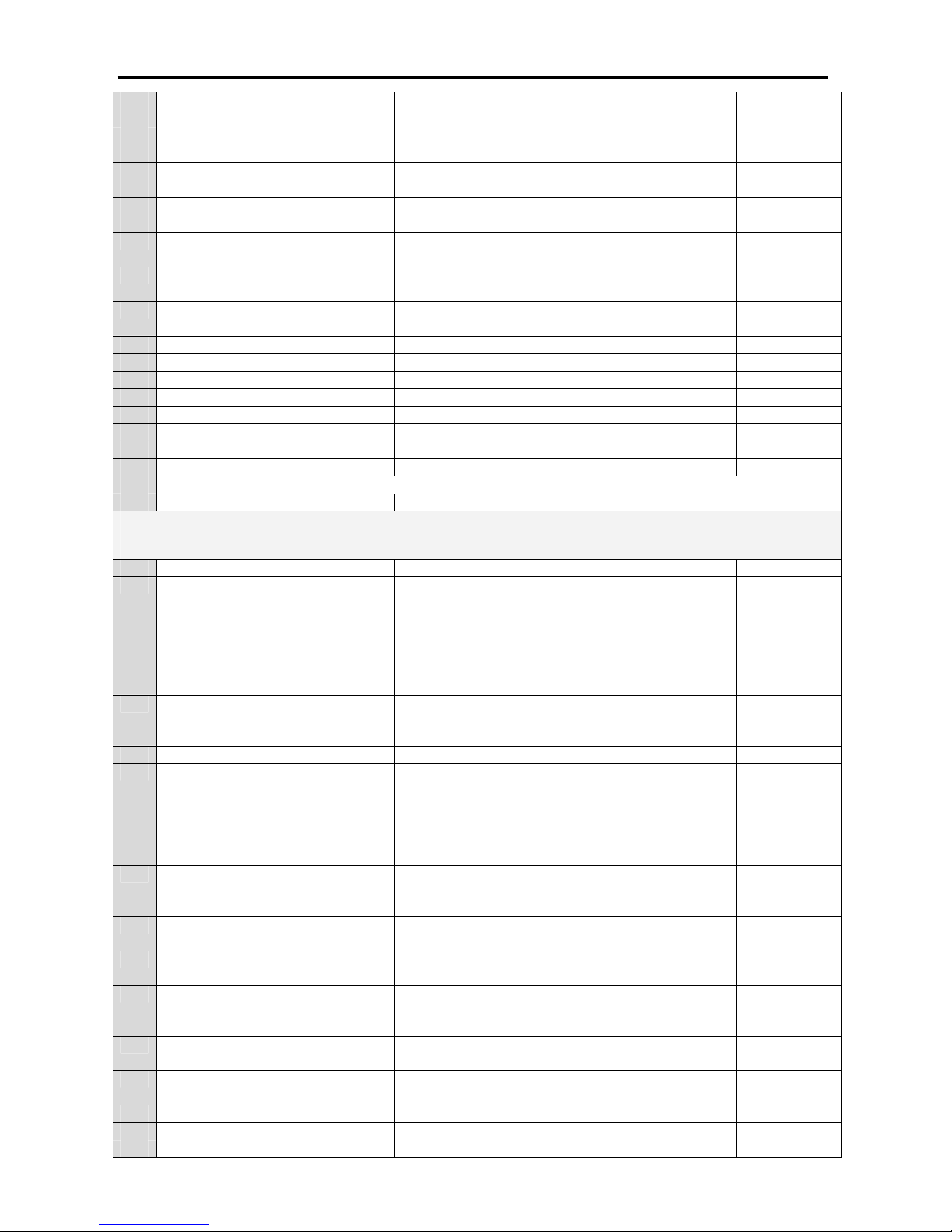
P23 Mains failure delay 0-120 sec 3 sec
P24 Transfer delay 1-60 sec 1 sec
P25 Alternator contactor delay 0-90 sec 2 sec
P26 Mains return delay 2-900 sec 5 sec
P27 Preheat time 0-300 sec 0 sec
P28 Generator voltage failure delay 2-20 sec 3 sec
P29 Generator frequency failure delay 2-20 sec 3 sec
P30 Horn time 0-900 sec 30 sec
P31 Current failure mode 0: Disabled
1: Enabled
1
P32 Crank disconnect on charge signal 0: Disabled
1: Enabled
0
P33 Crank disconnect on generator
voltage
20V-500V 165V
P34 Mains under voltage failure 46V-500V 184 V
P35 Mains under voltage return 46V-500V 194 V
P36 Mains over voltage return 46V-500V 244 V
P37 Mains over voltage failure 46V-500V 254 V
P38 Generator under voltage failure 46V-500V 184 V
P39 Generator over voltage failure 46V-500V 254 V
P40 Generator under frequency failure 10-75 Hz 42.5 Hz
P41 Generator over frequency failure 10-75 Hz 57.5 Hz
P42 Last 10 failure
P43 Return to operator factory defaults Yes / No
Technician Parameters
P44 Technician menu password 0-999 060
P45 Analog Oil sender type 0: Analog oil sender disabled
1: Analog Endiksan type
2: Analog Olcusan (VDO 7 Bar) type
3: Analog Olcusan (VDO 10 Bar) type
4: Analog Olcusan (VDO 80 PSI) type
5: Analog VDO 5 Bar
6: Analog AKSA type
6
P46 Oil switch type 0: Oil switch disabled
1: Normally closed for low pressure
2: Normally open for low pressure
0
P47 Low oil pressure level 0.1 – 9.5 bar 1.2 bar
P48 Analog temperature sender type 0: Not used
1: Analog Endiksan type
2: Analog Olcusan (VDO 120 C) type
3: Analog Volvo type
4: Analog AKSA type
5: Analog AKSA type 2
4
P49 Digital temperature switch type 0: Not used
1: Digital open for high temperature
2: Digital closed for high temperature
2
P50 Analog oil pressure sender usage 0: Only for indication
1: For indication and control
1
P51 Analog coolant temperature sender
usage
0: Only for indication
1: For indication and control
1
P52 Fueling system 0: Operating solenoid
1: Stop solenoid
2: ECU type
0
P53 Charging alternator 0: Charging alternator isn’t present
1: Charging alternator is present
1
P54 Crank disconnect alternator
frequency
10-30 Hz 21 Hz
P55 Crank disconnect oil pressure 0.5 – 9.5 bar 4.0 bar
P56 Crank disconnect oil pressure delay 1-30 sec 3 sec
P57 Before cranking oil pressure delay 1-10 sec 3 sec
Page 13
EN-KO Electronic Control Systems AMF 4.0/ENG/K.K./02
13
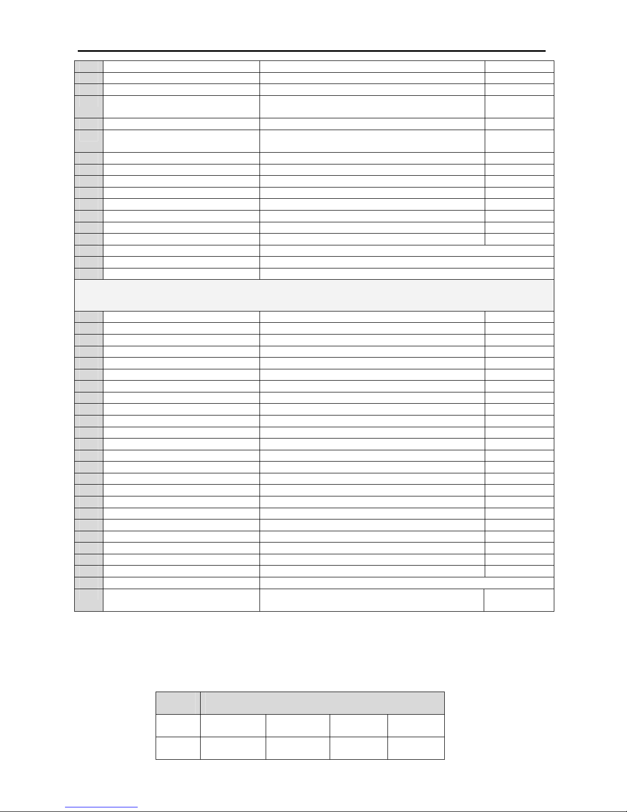
P58 Cooling Time 0-600 sec 180 sec
P59 Fail to stop delay 4-120 sec 30 sec
P60 Engine stabilization time 2-60 sec 10 sec
P61 Engine protection delay after
stopping
1-60 sec 3 sec
P62 Current transformer primary 5-900 200
P63 Parameter menu current multiplier 0: x1 mode
1: x10 mode
0
P64 Over current level 1-990 A 159 A
P65 Over current alarm delay 2-250 sec 30 sec
P66 High coolant temperature level 80 C – 140 C (176 – 284 F) 105 C (221 F)
P67 Battery low alarm level 0-40 V 24.0
P68 Battery high alarm level 0-40 V 30.0
P69 Automatic parameter load 0-41 10
P70 Periodic service time 10-5000 50
P71 Engine hour adjustment 0.0 - 99999.0 hour 0
P72 Clear last ten alarm Yes/ No
P73 Clear periodic service alarm Yes/ No
P74 Return to technician factory defaults Yes/ No
Calibration Parameters
P75 Calibration menu password 0-999 070
P76 Mains Vr gain 0.01-9.99 0.87
P77 Mains Vs gain 0.01-9.99 0.87
P78 Mains Vt gain 0.01-9.99 0.87
P79 Generator Vr gain 0.01-9.99 0.87
P80 Generator Vs gain 0.01-9.99 0.87
P81 Generator Vt gain 0.01-9.99 0.87
P82 Generator Ir gain 0.01-9.99 3.53
P83 Generator Is gain 0.01-9.99 3.53
P84 Generator It gain 0.01-9.99 3.53
P85 Battery Voltage gain 0.01-9.99 0.54
P86 Mains Vr offset -29,+29 V 0
P87 Mains Vs offset -29,+29 V 0
P88 Mains Vt offset -29,+29 V 0
P89 Generator Vr offset -29,+29 V 0
P90 Generator Vs offset -29,+29 V 0
P91 Generator Vt offset -29,+29 V 0
P92 Battery voltage offset -9.9,+9.9 0.8
P93 Oil pressure offset -9.9,+9.9 0.0
P94 Temperature offset -9,+9 0
P95 Generator Ir offset -0.99, +0.99 (for 5 A ) 0.00
P96 Generator Is offset -0.99, +0.99 (for 5 A ) 0.00
P97 Generator It offset -0.99, +0.99 (for 5 A ) 0.00
P98 Return to calibration factory defaults Yes / No
P99 Mains contactor control in off mode 0: No
1: Yes
1
CHANGED PARAMETERS FOR GENSET MODELS
Initial parameter settings are for genset model 10. Parameter settings are different for other
genset models. Parameters that are different from model 10 parameters are as following table.
Model number is used to select genset model in parameter 69
Models
Number
Changed
Parameters
0 P15 → 1
P62 →100
P45 → 3
P64 → 29
P52 → 1
P67 → 9
P53 → 0
P68 → 15
1 P15 → 1
P62 →100
P45 → 3
P64 → 36
P52 → 1
P67 → 9
P53 → 0
P68 → 15
Page 14

EN-KO Electronic Control Systems AMF 4.0/ENG/K.K./02
14
2 P15 → 1
P62 →100
P45 → 3
P64 → 48
P52 → 1
P67 → 9
P53 → 0
P68 → 15
3 P62 →100 P64 → 43
4 P15 → 1
P62 →100
P45 → 3
P64 → 54
P52 → 1
P53 → 0
5 P62 →100 P64 → 62
6 P15 → 1 P52 → 1 P62 →100 P64 → 64
7 P15 → 1 P52 → 1 P62 →100 P64 → 87
8 P62 →100 P64 → 87
9 P15 → 1 P52 → 1 P64 → 149
10 Default
parameters
11 P62 →300 P64 → 210
12 P15 → 1 P52 → 1 P62 →300 P64 → 269
13 P62 →300 P64 → 289
14 P15 →1 P48 → 2
P64 → 26
P52 → 1 P62 → 50
15 P48 → 2 P62 → 150 P64 → 130
16 P48 → 2 P62 → 250 P64 → 217
17 P48 → 2 P62 → 300 P64 → 289
18 P48 → 2 P62 → 500 P64 → 433
19 P48 → 2 P62 → 400 P64 → 360
20 P48 → 2 P62 → 500 P64 → 437
21 P48 → 2 P62 → 400 P64 → 383
22 P48 → 2 P62 → 600 P64 → 506
23 P48 → 2 P62 → 600 P64 → 542
24 P48 → 2 P62 → 100 P63 → 1 P64 → 98
25 P48 → 2 P62 → 100 P63 → 1 P64 → 99
26 P48 → 2 P62 → 125 P63 → 1 P64 → 103
27 P48 → 2 P62 →150 P63 → 1 P64 → 144
28 P15→1
P62→100
P53→0
P45→3
P64→17
P48→2
P67→9
P52→1
P68→15
29 P15→1
P62→100
P53→0
P45→3
P64→23
P48→2
P67→9
P52→1
P68→15
30 P15→1
P62→100
P53→0
P45→3
P64→48
P9→10
P48→2
P67→9
P52→1
P68→15
31 P15→1
P62→100
P45→6
P64→51
P48→2
P68→15
P52→1
P67→9
32 P15→1
P62→100
P45→6
P64→65
P48→2
P68→15
P52→1
P67→9
33 P15→1
P62→100
P45→6
P64→72
P48→2
P68→15
P52→1
P67→9
34 P15→1
P62→100
P45→6
P64→95
P48→2
P68→15
P52→1
P67→9
35 P15→0
P62→100
P45→6
P64→95
P48→4 P52→0
36 P15→1
P62→150
P45→6
P64→101
P48→2
P68→15
P52→1
P67→9
37 P15→0
P62→300
P45→6
P64→253
P48→4 P52→0
38 P15→0
P62→400
P45→6
P64→310
P48→2 P52→0
39 P15→0
P62→400
P45→6
P64→318
P48→2 P52→0
40 P15→0
P62→400
P45→6
P64→397
P48→2 P52→0
41 P15→0
P62→500
P45→6
P64→476
P48→2 P52→0
Page 15
EN-KO Electronic Control Systems AMF 4.0/ENG/K.K./02
15
PARAMETER DESCRIPTIONS
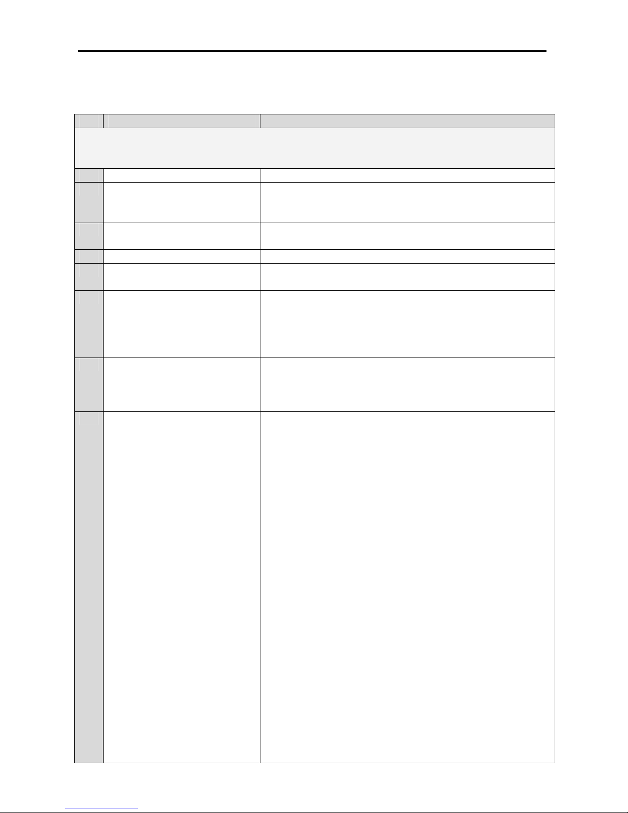
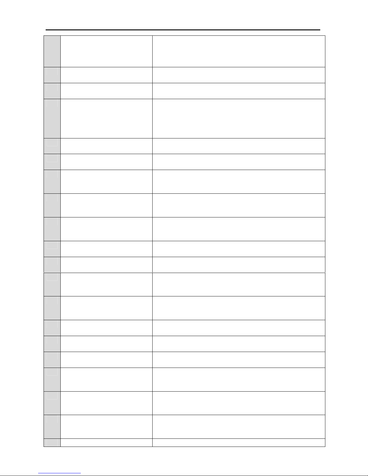
No Parameters Description
Operator Parameters
P0 Operator menu password Operator password can be changed by this parameter
P1 Temperature unit This parameter selects coolant temperature unit shown in the
display. According to selected unit “high coolant
temperature level“ is adjusted.
P2 Crank attempts Number of cranking during starting in automatic, test and
manual modes.
P3 Cranking time Cranking time during automatic cranking
P4 Cranking pause time Interval between two cranking period in automatic and test
modes.
P5 Manuel cranking type If this parameter selected”0”, operator must hold down start
button pressed during cranking period. If this parameter
selected “1” panel will perform cranking for “cranking
time”. Crank is disconnected automatically when panel
detects engine-running signals.
P6 Preheating type If this parameter selected”0”, operator must hold down
preheat button pressed during preheating period. If this
parameter selected “1” panel will perform preheating for
“Preheat time”.
P7 Auxiliary input 1 function It selects function of auxiliary input
• Auxiliary input can be adjusted as red or yellow
alarm. Activation time can be “always active, active
from engine starting or active from engine
stabilization time”. When input activates auxiliary
input led lit and A1.A2, A3 or A4 message is shown
according to activated auxiliary input number.
• When remote start input is activated generator starts
and generator contactor closes. If input deactivated
generator contactor opens, engine enters cooling
period and then generator stops. Remote start is
active only in automatic mode.
• When mains failure disable input is activated if
mains failure occur generator doesn’t start. Generator
opens mains contactor.
• If mains available input is activated panel assume
mains is available. If this input deactivated genset
return to its normal mode.
• If emergency stop button is pressed, generator opens
generator contactor and stops immediately. Panel
show “StP” message in the display. To clear
emergency stop alarm, emergency stop button must
be pulled back and alarm clear button must be
pressed.
• Cabin thermostat function is used in cabinet type
Page 16
EN-KO Electronic Control Systems AMF 4.0/ENG/K.K./02
16
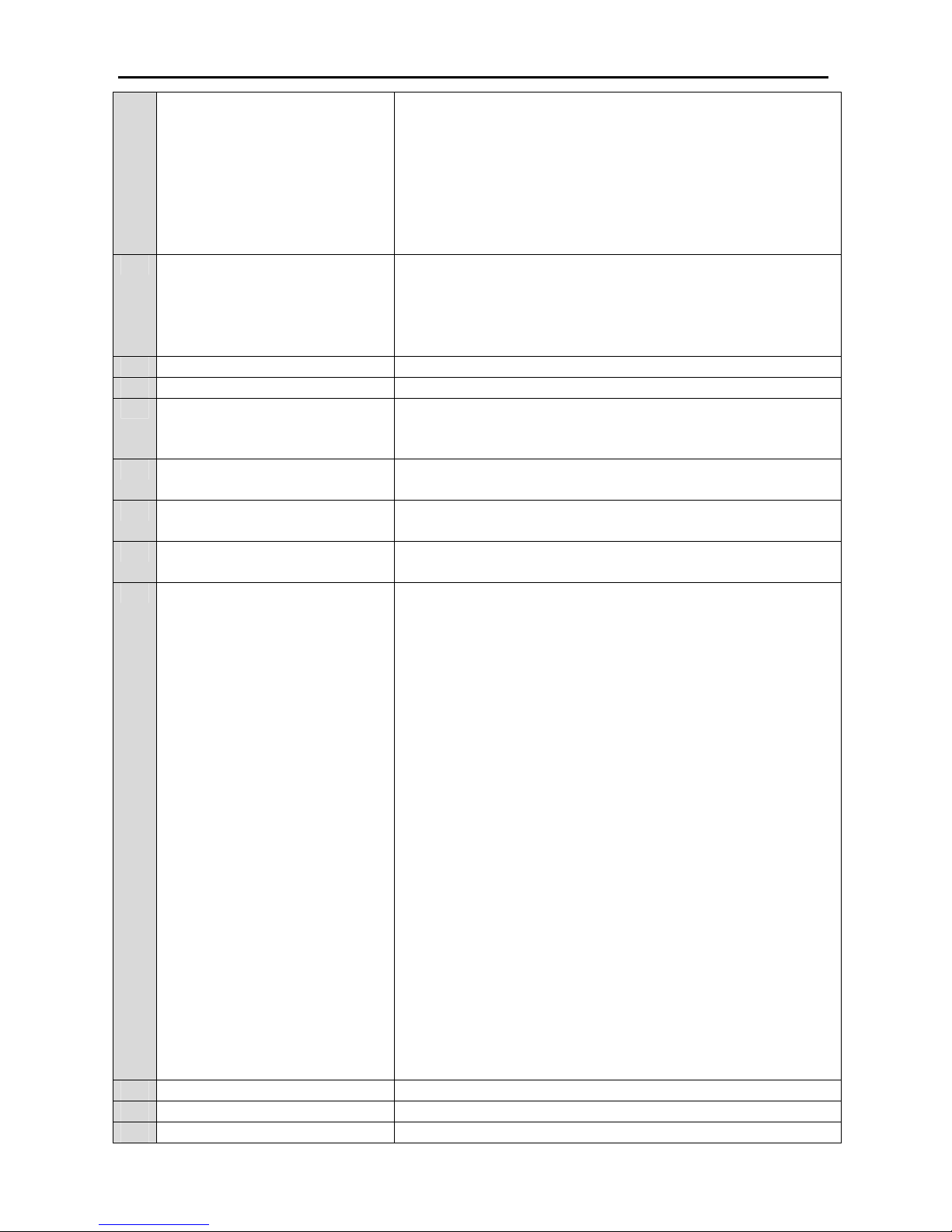
generators. Panel doesn’t control this input for 2
minute after engine start. After 2 minute if input is
still active panel gives alarm, open generator
contactor, cools engine then stop generator.
If oil pressure sender that has both sender and switch is
used, switch terminal must be connected to this input and
this parameter is disabled.
P8 Auxiliary input 2 function Functions are same as auxiliary input 1
If coolant temperature sender that has both sender and
switch is used, switch terminal must be connected to this
input and this parameter is disabled.
P9 Auxiliary input 3 function Functions are same as auxiliary input 1
P10 Auxiliary input 4 function Functions are same as auxiliary input 1
P11 Auxiliary input 1 activation
method
If this parameter is 0, input will be activated when it is
connected to battery negative. If this input is 1, input will be
activated, when input is disconnected from battery negative.
P12 Auxiliary input 2 activation
method
Same as auxiliary input 1
P13 Auxiliary input 3 activation
method
Same as auxiliary input 1
P14 Auxiliary input 4 activation
method
Same as auxiliary input 1
P15 Auxiliary output 1 function This parameter select the functions of auxiliary output 1
• Engine running: If engine running signal generator
voltage, frequency or charge alternator warning lamb
voltage is detected this output will be activated.
• Panel is in auto or test mode: If panel is in
automatic or test mode this output is activated.
• Yellow alarm: If yellow alarm occurs, this output is
activated.
• Red alarm: If red alarm occurs, this output is
activated.
• Common Alarm: If yellow or red alarm occurs, this
output is activated.
• Horn: If horn is activated. This output will close and
open by intervals of 1 second.
• Panel is in manual, auto or test mode: If panel is in
manual, automatic or test mode, this output will be
activated.
• Panel is in auto mode: If panel is in automatic
mode, this output will be activated.
• 6 sec stop output during engine stop: This output is
activated for 6 second during engine stopping
• Fuel solenoid output: This output can be used as
auxiliary fuel solenoid output
P16 Auxiliary output 2 function Same as auxiliary output 1
P17 Auxiliary output 3 function Same as auxiliary output 1
P18 Auxiliary output 1 activation If this parameter is selected as 0, when output is activated
Page 17
EN-KO Electronic Control Systems AMF 4.0/ENG/K.K./02
17
method output relay de-energizes. At startup when you supply
battery to panel this relay energizes and when output is
activated relay energizes. If this parameter is selected as 1,
when output activates, output relay energizes.
P19 Auxiliary output 2 activation
method
Same as auxiliary output 1
P20 Auxiliary output 3 activation
method
Same as auxiliary output 1
P21 Test Mode If this parameter is selected as “0”. In test mode, when
engine is started, load isn’t transferred to generator if mains
is available. If mains isn’t available generator contactor
closes. If this parameter is selected as “1” generator
contactor is closed, in test mode, without controlling mains
P22 Max stop solenoid working
time
This parameter is used to limit maximum working time of
stop solenoid.
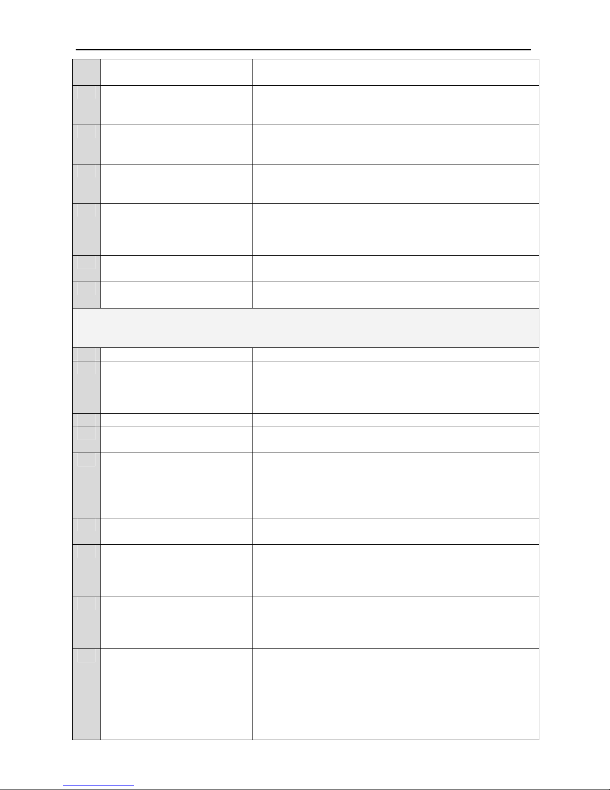
P23 Mains failure delay If mains is out of limits specified in the parameter menu,
Mains failure occur and generator starts.
P24 Transfer delay If generator contactor opens and mains contactor closes or
vice versa. Transfer time is waited between them. It is used
in test and automatic modes.
P25 Alternator contactor delay In automatic and test modes after engine stabilization time
alternator contactor delay is waited and alternator contactor
closes.
P26 Mains return delay If mains return from a mains failure condition. Mains return
delay is waited before mains accepted as normal. After this
delay in auto mode load transferred to mains.
P27 Preheat time This parameter defines, in automatic preheating, how long
preheating continues.
P28 Generator voltage failure delay When generator voltages are out of voltage limits, a voltage
alarm is given after “generator voltage failure delay”.
P29 Generator frequency failure
delay
When generator frequency is out of frequency limits, high
low speed alarm is given after “generator frequency failure
delay”.
P30 Horn time If horn output is activated. After “horn time” horn is
deactivated. If parameter is “0”, horn isn’t deactivated until
pressing alarm reset button.
P31 Current failure mode This parameter defines that alternator current alarms is
enabled or disabled.
P32 Crank disconnect on charge
signal
If this parameter is enabled. Crank is disconnected when
charge alternator voltage rises. (approx. 7 V)
P33 Crank disconnect on generator
voltage
If alternator voltage rises to the voltage level defined in this
parameter, Crank is disconnected.
P34 Mains under voltage failure If mains fall bellow this limit mains failure occur and
generator started in auto mode. Mains failure delay is waited
before mains failure.
P35 Mains under voltage return If mains exceeds this limit after a mains failure. Mains is
accepted normal after “mains return delay” and in auto mode
generator contactor is opened and generator is stopped.
P36 Mains over voltage return If mains fall below this limit after a mains failure. Mains is
accepted normal after “mains return delay” and in auto mode
generator contactor is opened and generator is stopped.
P37 Mains over voltage failure If mains exceeds this limit mains failure occur and generator
Page 18
EN-KO Electronic Control Systems AMF 4.0/ENG/K.K./02
18
started in auto mode. Mains failure delay is waited before
mains failure.
P38 Generator under voltage failure If generator voltage fall below this limit under over voltage
alarm occur. Failure occurred after generator voltage failure
delay
P39 Generator over voltage failure If generator voltage exceeds this limit under over voltage
alarm occur. Failure occurred after generator voltage failure
delay
P40 Generator under frequency
failure
If generator frequency fall below this limit under over speed
alarm occur. Failure occurred after generator frequency
failure delay
P41 Generator over frequency
failure
If generator frequency exceeds this limit under over speed
alarm occur. Failure occurred after generator frequency
failure delay
P42 Last 10 failure Last ten alarm is recorded in the panel memory. There alarm
can be controlled by this parameter.
P43 Return to operator factory
defaults
When you select “YES” and press menu key operator
parameters is returned to factory defaults
Technician Parameters
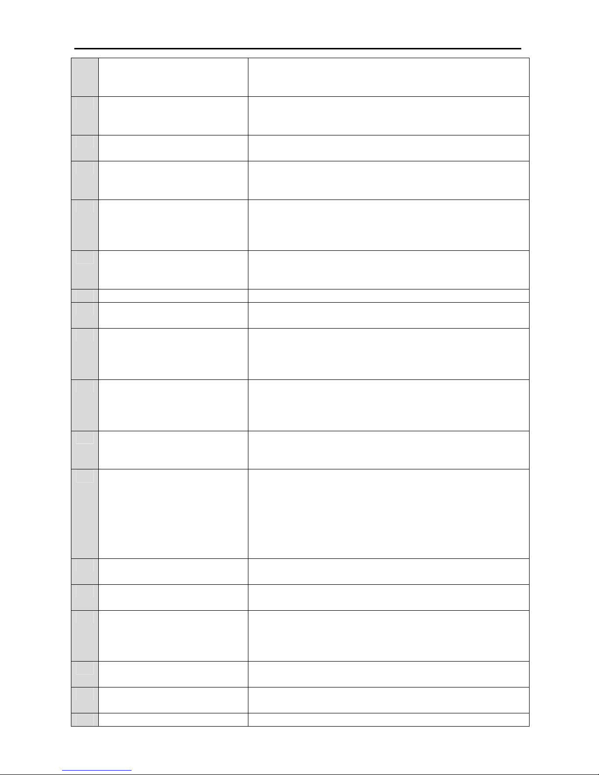
P44 Technician menu password Technician password can be changed by this parameter
P45 Analog oil sender type Analog oil pressure sender type can be selected from this
parameter. If genset has only digital oil switch, and this
parameter is adjusted to “0” oil switch input is transferred to
analog oil pressure sender input.
P46 Oil switch type Oil pressure switch type can be selected from this parameter.
P47 Low oil pressure failure If oil pressure fall below this limit. Oil pressure failure alarm
is activated.
P48 Analog temperature sender
type
Analog coolant temperature sender can be selected from this
parameter. If genset has only digital coolant temperature
switch, and this parameter is adjusted to “0” coolant
temperature switch input is transferred to analog temperature
sender input.
P49 Digital temperature switch type Analog coolant temperature sender can be selected from this
parameter.
P50 Analog Oil pressure usage If analog sender is used for display purposes only. Generator
doesn’t control this analog value. Value read from sender is
used only for display purposes. No sensor alarm is given if
sensor cable breaks.
P51 Analog temperature sensor
usage
If analog sender is used for display purposes only. Generator
doesn’t control this analog value. Value read from sender is
used only for display purposes. No sensor alarm is given if
sensor cable breaks.
P52 Fueling system Fueling system is can be adjusted as operating or stop
solenoid. When this parameter is selected as ECU type.
Cranking output behaves like start output and fuel solenoid
output behaves like stop output. This configuration is
necessary in some type of ECU managed engines. In engine
starting condition, start output is activated for 3 second and
cranking is stopped by means of activating stop output for 2
Page 19
EN-KO Electronic Control Systems AMF 4.0/ENG/K.K./02
19
second. In engine stopping condition stop output is activated
as 2 second cycling pulses.
P53 Charging alternator If parameter is adjusted as “0”. Charge alternator failure
doesn’t occur and crank doesn’t disconnected by charge
alternator.
P54 Crank disconnect alternator
frequency
In cranking if alternator frequency exceeds this limit crank
disconnected.
P55 Crank disconnect oil pressure In cranking if oil pressure exceed this limit and stay high,
after “crank disconnect oil pressure delay” crank
disconnected.
P56 Crank disconnect oil pressure
delay
In cranking if oil pressure rise, after “crank disconnect oil
pressure delay” crank disconnected.
P57 Before cranking oil pressure
delay
If oil pressure is high before cranking this delay is waited. If
oil pressure is fall down cranking begins. If oil pressure
doesn’t fall panel give fail to start stop alarm.
P58 Cooling Time Parameter contains how long cooling period continue
P59 Fail to stop delay In stopping period, parameter defines how long panel will
wait for engine to stop before giving fail to start stop alarm.
P60 Engine stabilization time When generator starts all engine alarms will be delayed for
engine stabilization time. During this time all values read
from sensors stabilize (Alternator voltage, frequency, charge
alternator warning lamp voltage and oil pressure).
P61 Engine protection delay after
stopping
In stopping period after panel detected all engine running
signals absent, panel will wait an additional protection delay
This is necessary for engine to stop completely before next
engine start. Do not decrease this value if not necessary.
P62 Current transformer primary This parameter contains current transformer primary value.
If Current transformer primary is more than 999 you must
change parameter menu current multiplier to x10 mode.
P63 Parameter menu current
multiplier
If this parameter is made x10, Parameter “P62: current
transformer primary” and”P64: over current level” are
multiplied by 10. You must use this parameter if values are
bigger than 999. For example for 2500:5 current transformer
and 2000 Amp over current level. After setting parameter
menu current multiplier x10, you must set current
transformer primary as 250 and over current level 200.
P64 Over current level If measured alternator current exceeds value that parameter
contains. Over current alarm will be given.
P65 Over current alarm delay If over current condition occur more than over current alarm
delay. Panel will give over current alarm.
P66 High coolant temperature level If engine coolant temperature exceeds the value that this
parameter contain. Panel will give high coolant temperature
alarm. This parameter must be entered according to
parameter temperature unit.
P67 Battery low alarm level If battery voltage falls below voltage level that parameter
contains battery high low alarm will be given.
P68 Battery high alarm level If battery voltage exceeds voltage level that parameter
contains battery high low alarm will be given.
P69 Automatic parameter load Parameter tables according to genset models can be loaded.
Page 20
EN-KO Electronic Control Systems AMF 4.0/ENG/K.K./02
20
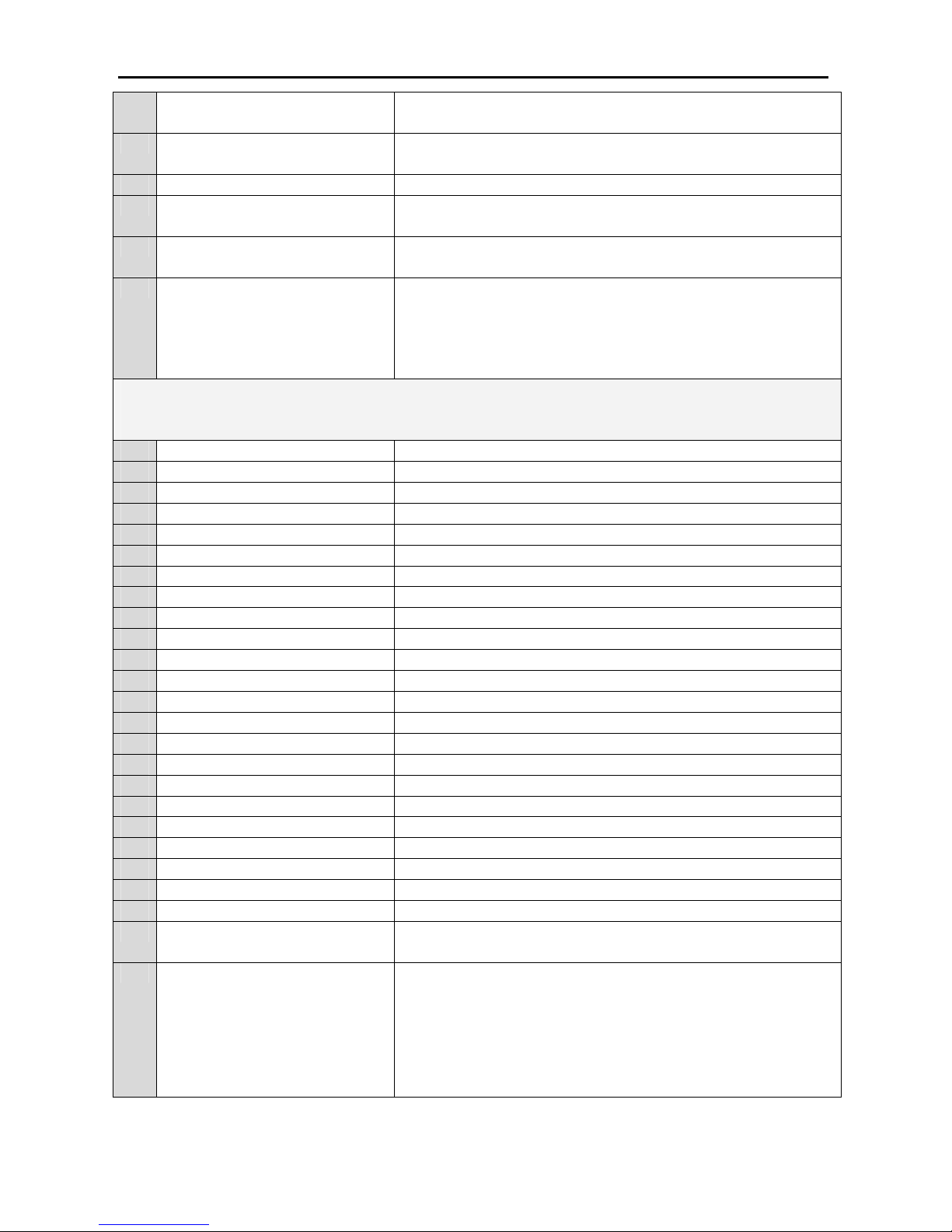
Enter model number to load parameter table of selected
genset model.
P70 Periodic service time This parameters selects After how many running hour
periodic service alarm will be given
P71 Engine hour adjustment Engine hour is adjusted by this parameter.
P72 Clear last ten alarm When you select “YES” and press menu key last ten failure
is cleared.
P73 Clear periodic service alarm When you select “YES” and press menu key, periodic
service alarm is cleared and service time is reset
P74 Return to technician factory
defaults
When you select “YES” and press menu key technician
parameters is returned to factory defaults
Calibration Parameters
P75 Calibration menu password Calibration menu password adjustment
P76 Mains Vr gain Mains line R voltage gain calibration.
P77 Mains Vs gain Mains line S voltage gain calibration.
P78 Mains Vt gain Mains line T voltage gain calibration.
P79 Generator Vr gain Generator line R voltage gain calibration.
P80 Generator Vs gain Generator line S voltage gain calibration.
P81 Generator Vt gain Generator line T voltage gain calibration.
P82 Generator Ir gain Generator line R current gain calibration.
P83 Generator Is gain Generator line S current gain calibration.
P84 Generator It gain Generator line T current gain calibration.
P85 Battery Voltage gain Battery voltage gain calibration.
P86 Mains Vr offset Mains line R voltage offset calibration.
P87 Mains Vs offset Mains line S voltage offset calibration.
P88 Mains Vt offset Mains line T voltage offset calibration.
P89 Generator Vr offset Generator line R voltage offset calibration.
P90 Generator Vs offset Generator line S voltage offset calibration.
P91 Generator Vt offset Generator line T voltage offset calibration.
P92 Battery voltage offset Battery voltage offset calibration.
P93 Oil pressure offset Oil pressure offset calibration.
P94 Temperature offset Coolant temperature offset calibration.
P95 Generator Ir offset Generator line R current offset calibration.
P96 Generator Is offset Generator line S current offset calibration.
P97 Generator It offset Generator line T current offset calibration.
P98 Return to calibration factory
defaults
When you select “YES” and press menu key calibration
parameters is returned to factory defaults
P99 Mains contactor control in off
mode
If this parameter is selected as “YES”, Unit will control
mains voltages in off mode and when mains exceed the
limits defined in parameter menu, mains contactor opens and
protect the load and when mains returns to normal condition
mains contactor closes. If this parameter is selected as “NO”,
mains isn’t controlled and mains contactor is always closed.
Page 21
EN-KO Electronic Control Systems AMF 4.0/ENG/K.K./02
21
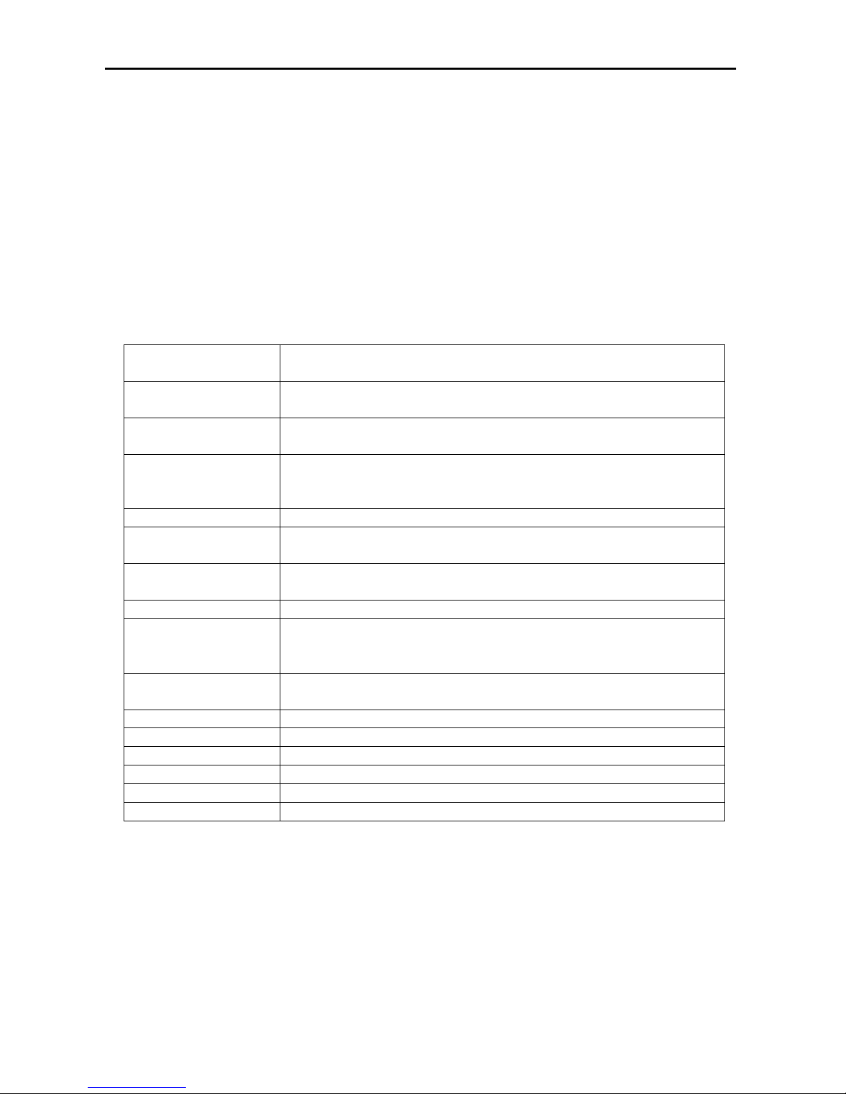
SPECIFICATIONS
Power Supply
9-35 VDC
140 mA (all relays are de-energized)
Ambient
Temperature
-10°C / +70°C
Relative Humidity
%10-%95 non-condensing
Relay outputs
For cranking, fuel solenoid, preheating and auxiliary outputs max.
12V/24VDC 6 A, For mains and generator contactor relays max.
250VAC/10 A
Voltage measurement
20-300VAC
Frequency
measurement
1-99 Hz
Current
measurements
.../5 A current inputs (current transformer should be used)
Connection
Screw socket
Measurement
Accuracy
Phase voltages : + / - %2
Frequency : + / - 0.1Hz
Phase currents : + / - %2
Charge Excitation
Current
80mA @ 12VDC
160mA@ 24VDC
Housing
PPO (Polyphenylene oxide) %30 Glass Fiber
Protection Class
IP 52 (Front side)
Weight
600 gr. (aprox.)
Dimensions (WxHxD)
192x144x62 mm
Panel Cut Out
186x138 mm
Mounting Installation
Front panel mounted with metal screw fixings
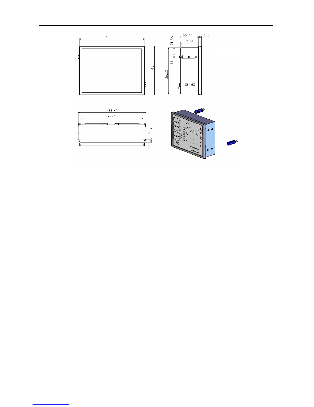
DIMENSIONS AND MOUTING
Page 22
EN-KO Electronic Control Systems AMF 4.0/ENG/K.K./02
22
Dimensions in mm
" Specifications are subject to change without notice."
 Loading...