

Page 1
2048 Mercer Road Lexington, Kentucky 40511 • 800-322-8346 or 859-233-4599 • http://www.audioauthority.com/aviation
Piper PA-32 Saratoga Installation Example
Enhanced Flight Model BM-AIK
Airframe Interface Kit for BatteryMINDer®"Maintenance Charger
This installation example supplements the instructions for installing the BM-AIK1 or BM-AIK2 charger
harness kit. Please read the instructions with the kit completely before referring to this example. The kit
instructions call for connecting to the battery relay and an airframe ground, instead of directly to the battery.
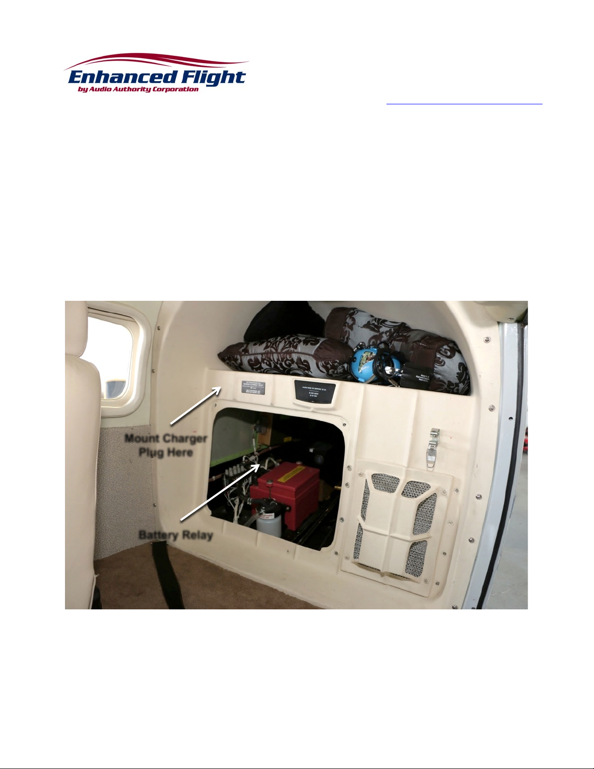
The relay and an existing airframe ground are readily accessible in the Saratoga as shown below. The exact
configuration of your aircraft may vary from this example and require slight changes from these instructions.
1) Battery installation is accessed through a removable panel in the aft baggage closeout. The battery
relay is located outboard of the battery.
2) Begin by assembling the plug end of the harness – solder one end of the red & black harness wires
to the SB50 contacts, then insert the contacts into the plug.
3) Mount the SB50 plug to the outside of the closeout panel with standard AN washers stacked to
space it off the panel about ¼” to provide clearance for the dust cover and allow easy access for the
mating connector. Pass the harness wires through the closeout at the rear of the connector and
route them down behind the panel to follow an existing wire bundle aft.
Mount Charger
Plug Here
Battery Relay
Page 2
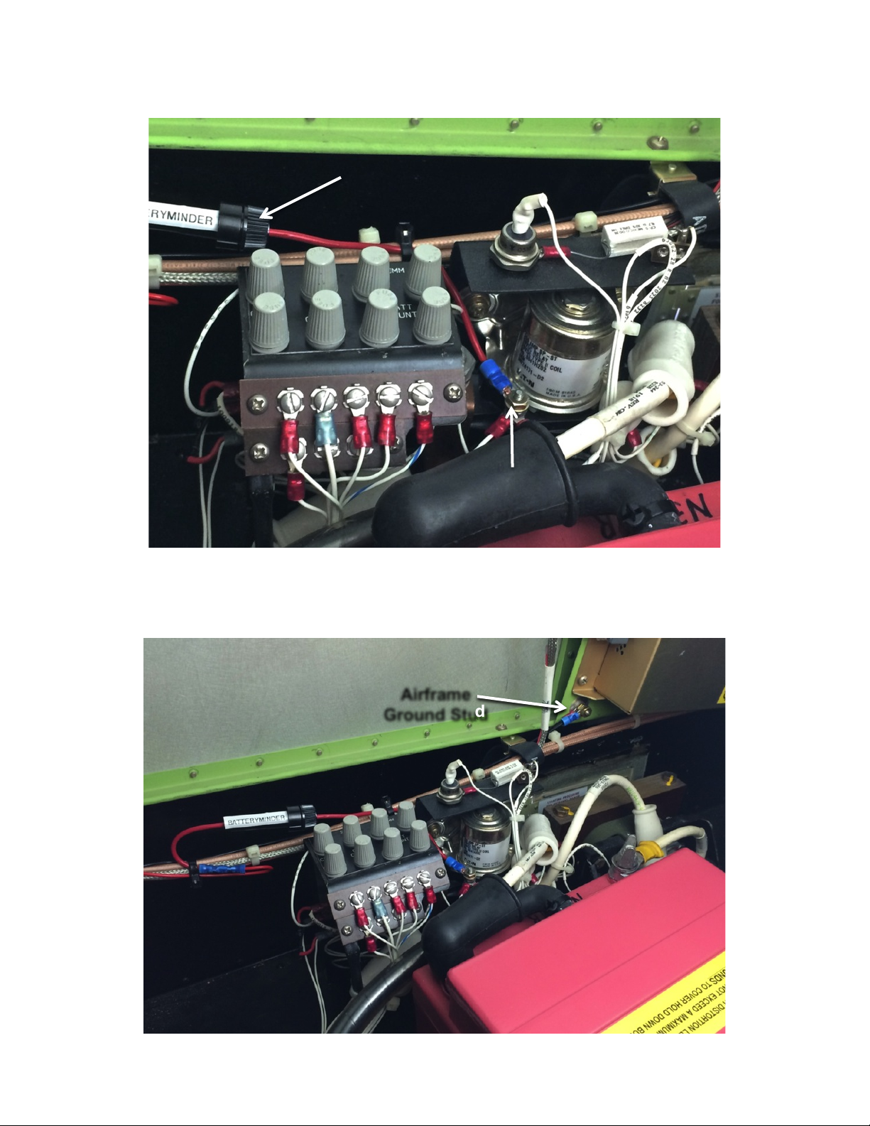
4) Assemble the fuseholder and connect one end to the battery relay stud using a ring terminal. Route
the fuseholder assembly to follow the existing wire bundle. Cover relay terminal with rubber boot.
5) Trim the positive (red) harness lead to length and connect to the open fuseholder wire using the
supplied butt splice. Secure wires and fuseholder to the existing wire bundle.
6) Route the ground wire (black) following the same path to an existing airframe ground and connect
with ring terminal. Secure to wire bundle with ties.
Fuseholder
Positive Stud
On Relay
Airframe
Ground Stud
Page 3
7) Check continuity and polarity of harness at the SB50 connector with voltmeter.
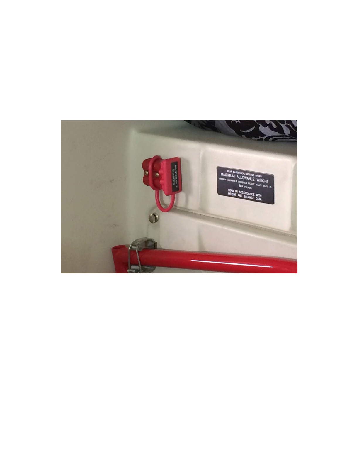
8) Label SB50 connector “MAINTENANCE CHARGER.”
9) Connect BatteryMINDer to aircraft and check for proper operation.
10) Re-install closeout access panel, tow bar, etc.
11) Perform cockpit electrical system test for normal operation.
12) Make appropriate entry in airframe maintenance logbook to document installation and return to
service.
Finished installation with dust cover labeled, ready to connect BatteryMINDer.
 Loading...