

SFX/SFX12V Power Supply Design
Guide
Version 2.2
Document Revision
Version Release Date Notes
1.0 12/97 Public release
1.1 4/98
2.0 5/01 • Added SFX12V description
2.1 8/01 • Section 4.4 Updated Figure 4 SFX/SFX12V Connectors
• Updated all mechanical outlines to clean up
dimensioning of mounting holes.
• Added chassis cutouts for all mechanical outlines to
clarify keep-out areas.
• Added Appendix C.
• Additional power ratings added
• Updated industry standards
• Increased standby current
• Section 5.8 removed vendor name
2.2 12/05 • Section 3.23 Typical Power Distribution. Change minimum loading
on 5V rail to 0.3A
• Section 3.3.2 PS_ON#. Add text “The power supply should not
latch into a shutdown state when PS_ON# is driven active by
pulses between 10ms to 100ms during the decay of the power
rails.”

SFX/SFX12V Power Supply Design Guide
Version 2.2
IMPORTANT INFORMATION AND DISCLAIMERS
1. INTEL CORPORATION (AND ANY CONTRIBUTOR) IS PROVIDING THIS INFORMATION AS
A CONVENIENCE AND ACCORDINGLY MAKES NO WARRANTIES WITH REGARD TO THIS
DOCUMENT. IN PARTICULAR, INTEL (AND ANY CONTRIBUTOR) DOES NOT WARRANT OR
REPRESENT THAT THIS DOCUMENT OR ANY PRODUCTS MADE IN CONFORMANCE WITH IT
WILL OPERATE IN THE INTENDED MANNER. NOR DOES INTEL (OR ANY CONTRIBUTOR)
ASSUME RESPONSIBILITY FOR ANY ERRORS THAT THE DOCUMENT MAY CONTAIN.
2. NO REPRESENTATIONS OR WARRANTIES ARE MADE THAT ANY PRODUCT BASED IN
WHOLE OR IN PART ON THE ABOVE DOCUMENT WILL BE FREE FROM DEFECTS OR SAFE FOR
USE FOR ITS INTENDED PURPOSE. ANY PERSON MAKING, USING OR SELLING SUCH
PRODUCT DOES SO AT HIS OR HER OWN RISK.
3. INTEL DISCLAIMS ALL LIABILITY ARISING FROM USE OF OR IN CONNECTION WITH
THE INFORMATION PROVIDED IN THIS DOCUMENT, INCLUDING LIABILITY FOR
INFRINGEMENT OF ANY PROPRIETARY RIGHTS RELATING TO THE INFORMATION OR THE
IMPLEMENTATION OF INFORMATION IN THIS DOCUMENT. INTEL DOES NOT WARRANT OR
REPRESENT THAT SUCH DEVICES OR IMPLEMENTATION WILL NOT INFRINGE SUCH RIGHTS.
INTEL IS NOT OBLIGATED TO PROVIDE ANY SUPPORT, INSTALLATION OR OTHER
ASSISTANCE WITH REGARD TO THE INFORMATION.
4. THE INFORMATION REFERRED TO IN THIS DOCUMENT IS INTENDED FOR STANDARD
COMMERCIAL USE ONLY. CUSTOMERS ARE SOLELY RESPONSIBLE FOR ASSESSING THE
SUITABILITY OF THE INFORMATION FOR USE IN PARTICULAR APPLICATIONS. THE
INFORMATION IS NOT INTENDED FOR USE IN CRITICAL CONTROL OR SAFETY SYSTEMS,
MEDICAL OR LIFE SAVING APPLICATIONS, OR IN NUCLEAR FACILITY APPLICATIONS.
5. NO LICENSE, EXPRESS OR IMPLIED, BY ESTOPPEL OR OTHERWISE, TO ANY
INTELLECTUAL PROPERTY RIGHTS IS GRANTED HEREIN.
Copyright 2000, 2001 Intel Corporation. All rights reserved.
Version 0.9 of updated SFX PSDG, Mar 2001
†
Third-party brands and names are the property of their respective owners.
Page 2

SFX/SFX12V Power Supply Design Guide
Version 2.2
Contents
1. Introduction....................................................................................................................................6
1.1. Scope.....................................................................................................................................6
1.2. Proposed changes for Version 2.0.........................................................................................6
1.2.1. Reformat....................................................................................................................6
1.2.2. Increased Power........................................................................................................6
1.2.3. Increased +5 VSB Current ........................................................................................6
1.2.4. External Fan Control - Optional..................................................................................6
1.2.5. SFX12V......................................................................................................................7
2. Applicable Documents..................................................................................................................7
3. Electrical.........................................................................................................................................9
3.1. AC Input .................................................................................................................................9
3.1.1. Input Overcurrent Protection .....................................................................................9
3.1.2. Inrush Current Limiting..............................................................................................9
3.1.3. Input Under Voltage...................................................................................................10
3.1.4. Regulatory.................................................................................................................10
3.1.5. Catastrophic Failure Protection.................................................................................10
3.2. DC Output ..............................................................................................................................10
3.2.1. DC Voltage Regulation..............................................................................................10
3.2.2. Remote Sensing........................................................................................................11
3.2.3. Typical Power Distribution.........................................................................................11
3.2.4. Power Limit / Hazardous Energy Levels....................................................................13
3.2.5. Efficiency...................................................................................................................13
3.2.6. Output Ripple/Noise ..................................................................................................14
3.2.7. Output Transient Response ......................................................................................15
3.2.8. Capacitive Load.........................................................................................................16
3.2.9. Closed-loop Stability..................................................................................................16
3.2.10. +5 VDC / +3.3 VDC Power Sequencing..................................................................16
3.2.11. Voltage Hold-up Time..............................................................................................16
3.3. Timing / Housekeeping / Control............................................................................................17
3.3.1. PWR_OK...................................................................................................................17
3.3.2. PS_ON# ....................................................................................................................18
3.3.3. +5 VSB ......................................................................................................................19
3.3.4. Power-on Time..........................................................................................................19
3.3.5. Rise Time..................................................................................................................19
3.3.6. Overshoot at Turn-on / Turn-off ................................................................................20
3.3.7. Reset after Shutdown................................................................................................20
3.3.8. +5 VSB at AC Power-down .......................................................................................20
3.4. Output Protection ...................................................................................................................20
3.4.1. Over Voltage Protection ............................................................................................20
3.4.2. Short-circuit Protection..............................................................................................20
Page 3

SFX/SFX12V Power Supply Design Guide
Version 2.2
3.4.3. No-load Operation.....................................................................................................21
3.4.4. Over Current Protection.............................................................................................21
3.4.5. Over-Temperature Protection....................................................................................21
3.4.6. Output Bypass...........................................................................................................21
4. Mechanical .....................................................................................................................................21
4.1. Labeling / Marking..................................................................................................................21
4.2. Airflow / Fan ...........................................................................................................................22
4.3. AC Connector.........................................................................................................................22
4.4. DC Connectors.......................................................................................................................23
4.4.1. SFX Main Power Connector......................................................................................24
4.4.2. Peripheral Connector(s) ............................................................................................25
4.4.3. Floppy Drive Connector.............................................................................................25
4.4.4. +12 V Power Connector (for SFX12V only)...............................................................25
5. Environmental................................................................................................................................26
5.1. Temperature...........................................................................................................................26
5.2. Thermal Shock (Shipping)......................................................................................................26
5.3. Humidity .................................................................................................................................26
5.4. Altitude ...................................................................................................................................26
5.5. Mechanical Shock..................................................................................................................26
5.6. Random Vibration...................................................................................................................27
5.7. Acoustics................................................................................................................................27
5.8. Ecological Requirements.......................................................................................................27
6. Electromagnetic Compatibility.....................................................................................................28
6.1. Emissions...............................................................................................................................28
6.1.2 Immunity................................................................................................................................28
6.2. Input Line Current Harmonic Content ....................................................................................28
6.3. Magnetic Leakage Fields .......................................................................................................29
6.4. Reliability................................................................................................................................29
6.5. Mean Time Between Failures (MTBF)...................................................................................29
6.6. Voltage Fluctuations and Flicker...........................................................................................30
7. Safety..............................................................................................................................................30
7.1. North America........................................................................................................................30
7.2. International............................................................................................................................31
8....SYSTEM COOLING CONSIDERATIONS......................................................................................31
APPENDIX A GUIDELINES FOR A LOWER PROFILE PACKAGE ......................................32
APPENDIX B GUIDELINES FOR A TOP MOUNT FAN PACKAGE ......................................34
APPENDIX C GUIDELINES FOR A REDUCED DEPTH, TOP MOUNT FAN PACKAGE.....37
APPENDIX D GUIDELINES FOR A LOWER PROFILE PACKAGE......................................40
Page 4

SFX/SFX12V Power Supply Design Guide
Version 2.2
Figures
Figure 1. Differential Noise Test Setup.................................................................................................15
Figure 2. Power Supply Timing.............................................................................................................17
Figure 3. PS_ON# Signal Characteristics.............................................................................................19
Figure 4. SFX/SFX12V Connectors......................................................................................................23
Figure 5 40 mm Profile Mechanical Outline..........................................................................................33
Figure 6 Chassis Cutout.......................................................................................................................33
Figure 7 Top Mount Fan Profile Mechanical Outline ............................................................................35
Figure 8 Chassis Cutout.......................................................................................................................36
Figure 9 Recessed Fan Mounting.........................................................................................................36
Figure 10 Reduced Depth Top Mount Fan Profile Mechanical Outline ................................................38
Figure 11 Chassis cutout......................................................................................................................39
Figure 12 60 mm Mechanical Outline...................................................................................................41
Figure 13 Chassis Cutout.....................................................................................................................42
Tables
Table 1. AC Input Line Requirements...................................................................................................9
Table 2. DC Output Voltage Regulation ...............................................................................................10
Table 3. Typical Power Distribution for a 90 W SFX Configuration......................................................11
Table 4. Typical Power Distribution for a 120 W SFX Configuration....................................................11
Table 5. Typical Power Distribution for a 150 W SFX Configuration...................................................12
Table 6. Typical Power Distribution for a 160 W SFX12V Configuration..............................................12
Table 7. Typical Power Distribution for 180 W SFX12V Configuration.................................................13
Table 8 Energy Star Input Power Consumption.................................................................................14
Table 9. DC Output Noise/Ripple .........................................................................................................14
Table 10. DC Output Transient Step Sizes...........................................................................................15
Table 11. Output Capacitive Loads ......................................................................................................16
Table 12. PWR_OK Signal Characteristics..........................................................................................18
Table 13. PS_ON# Signal Characteristics............................................................................................18
Table 14. Over Voltage Protection........................................................................................................20
Table 15: Harmonic Limits, Class A equipment....................................................................................29
Page 5

SFX/SFX12V Power Supply Design Guide
Version 2.2
1. Introduction
1.1. Scope
This document provides design suggestions for a family of small form factor power supplies that
are primarily intended for use with microATX and FlexATX systems. The connectors conform
to the basic requirements of the ATX main board specification except that -5 V is not available.
It should not be inferred that all SFX power supplies must conform exactly to the content of this
document. The design specifics described are not intended to support all possible systems,
because power supply needs vary depending on system configuration.
1.2. Proposed changes for Version 2.0
This section provides a brief summary of the proposed changes to revise the SFX Power Supply
Design Guide from Version 1.1 to Version 2.0.
1.2.1. Reformat
This design guide has been reformatted to more clearly show the case outline options.
1.2.2. Increased Power
The trend for faster and more powerful systems results in an increasing need for higher rated
power supplies. Additional power ratings have been added with increased 5 VDC and 12 VDC
current to meet the needs of present and future system needs. Power ratings have been added at
120 W and 150 W. These have been added for guidance and are not intended to limit the choice
of power ratings available.
1.2.3. Increased +5 VSB Current
Trends in PC system power management solutions (for example, Instantly Available PC and
Suspend-to-RAM) are driving a need for increased +5 VSB current capability for all SFX-family
power supplies. The previous +5 VSB output requirement is being raised to 1.0 amps minimum,
with 2.0 amps preferred. Recommendations for momentary peak current have also been added to
enable USB "wake on" devices. See Section 3.3.3 for details.
1.2.4. External Fan Control - Optional
With the implementation of Suspend To RAM (STR or S3 sleep state), the system can obtain a
low power condition without the need for external fan shutoff. In STR mode, the main outputs
including 12 V are not available from the power supply and all system fans and the power supply
fan will be off. FANC and FANM functions described in Version 1.1 have been removed for
Version 2.0. Some vendors may still offer the external Fan functions as an option.
Page 6
SFX/SFX12V Power Supply Design Guide
Version 2.2
1.2.5. SFX12V
The latest generation of motherboards will have power delivery based on a 12 V rail. To meet
the needs of the higher 12 V current, a new connector has been defined to meet the increased
current needs of these motherboards. Wattages at 160 W and 180 W have been defined to meet
the requirements of Intel Pentium® 4 processor-based systems.
2. Applicable Documents
The latest revision in effect of the following documents forms a part of this document to the
extent specified.
Document title Description
AB13-94-146
ANSI C62.41-1991 IEEE Recommended Practice on Surge Voltages in Low-Voltage AC Circuits
ANSI C62.45-1992 IEEE Guide on Surge Testing for Equipment Connected to Low-Voltage AC Power
MIL-STD-105K Quality Control
MIL-STD-217F Reliability Predictions for Electronic Equipment
MIL-C-5541 Chemical Conversion Coatings on Aluminum and Aluminum Alloys
CSA C22.2 No.234, Level 3 Safety of Component Power Supplies (Intended for use with Electronic Data
CAN/CSA C22.2 No.950-95,
3rd edition
UL 1950, 3rd edition, without D3
Deviation
IEC 60950, 2nd ed. 1991: plus
A1, A2, A3, A4
EN 60950, 2nd ed. 1992: plus
A1, A2, A3, A4
EMKO-TSE (74-SEC) 207/94 Nordic national requirement in addition to EN 60950
CISPR 22:1997 3rd edition
EN 55022:1998
ANSI C63.4 – 1992 American National Standard for Methods of Measurement of Radio-Noise
AS/NZS 3548 (Class B) Australian Communications Authority, Standard for Electromagnetic Compatibility
CNS 13438 Limits and methods of measurement of radio disturbance characteristics of
EN 55024:1998 Information technology equipment—Immunity characteristics—Limits and methods
European Association of Consumer Electronics Manufacturers (EACEM)
Hazardous Substance List / Certification
Circuits
Processing Equipment and Office Machines)
Safety of Information Technology Equipment Including Electrical Business
Equipment
Safety of Information Technology Equipment Including Electrical Business
Equipment
Safety of Information Technology Equipment Including Business Equipment
Safety of Information Technology Equipment Including Business Equipment
Limits and Methods of Measurements of Radio Interference Characteristics of
Information Technology Equipment, Class B
Emissions from Low-Voltage Electrical and Electronic Equipment in the Range of 9
kHz to 40 GHz for EMI testing
(AU & NZ)
Information Technology Equipment (Taiwan & China)
of measurement
Page 7
SFX/SFX12V Power Supply Design Guide
Version 2.2
CISPR 24: 1997 Information technology equipment—Immunity characteristics—Limits and methods
of measurement
EN 61000-3-2 Electromagnetic compatibility (EMC)—Part 3: Limits—Section 2: Limits for
harmonic current emissions, Class D
IEC 61000-4- Electromagnetic compatibility (EMC) for industrial-process measurement and
control equipment—Part 4: Testing and measurement techniques
Section -2: Electrostatic discharge
Section -3: Radiated, radio-frequency, electromagnetic field
Section -4: Electrical fast transient / burst
Section -5: Surge
Section -6: Conducted disturbances, induced by radio-frequency fields
Section -8: Power frequency magnetic fields
Section -11: Voltage dips, short interruptions, and voltage variations
Japan Electric Association Guidelines for the Suppression of Harmonics in Appliances and General Use
Equipment
IEC Publication 417 International Graphic Symbol Standard
ISO Standard 7000 Graphic Symbols for Use on Equipment
CFR 47, Part 15, Subpart B FCC Regulations pertaining to unintentional radiators (USA)
ICES-003 (Class B) Interference-Causing Equipment Standard, Digital Apparatus (Canada)
VCCI V-3/99.05 (Class B) Implementation Regulations for Voluntary Control of Radio Interference by Data
processing Equipment and Electronic Office Machines (Japan)
Page 8
SFX/SFX12V Power Supply Design Guide
Version 2.2
3. Electrical
The electrical requirements that follow are to be met over the environmental ranges specified in
Section 5 unless otherwise noted.
3.1. AC Input
Table 1 lists AC input voltage and frequency requirements for continuous operation. The power
supply shall be capable of supplying full-rated output power over two input voltage ranges rated
100-127 VAC and 200-240 VAC rms nominal. The correct input range for use in a given
environment may be either switch-selectable or auto-ranging. The power supply shall
automatically recover from AC power loss. The power supply must be able to start up under
peak loading at 90 VAC.
Table 1. AC Input Line Requirements
Parameter Minimum Nominal
(Note)
Vin (115 VAC) 90 115 135 VAC
Vin (230 VAC) 180 230 265 VAC
Vin Frequency 47 -- 63 Hz
Note: Nominal voltages for test purposes are considered to be within ±1.0 V of nominal.
Maximum Unit
rms
rms
3.1.1. Input Overcurrent Protection
The power supply shall incorporate primary fusing for input overcurrent protection to prevent
damage to the power supply and meet product safety requirements. Fuses should be slow-blow–
type or equivalent to prevent nuisance trips1.
3.1.2. Inrush Current Limiting
Maximum inrush current from power-on (with power on at any point on the AC sine) and
including, but not limited to, three line cycles, shall be limited to a level below the surge rating of
the input line cord, AC switch if present, bridge rectifier, fuse, and EMI filter components.
Repetitive ON/OFF cycling of the AC input voltage should not damage the power supply or
cause the input fuse to blow.
1
. For Denmark and Switzerland international safety requirements, if the internal over-current protective
devices exceed 8A for Denmark and 10A for Switzerland, then the power supply must pass international
safety testing to EN 60950 using a maximum 16A over-current protected branch circuit, and this 16A (time
delay fuse) branch circuit protector must not open during power supply abnormal operation (output short
circuit and component fault) testing.
Page 9

SFX/SFX12V Power Supply Design Guide
Version 2.2
3.1.3. Input Under Voltage
The power supply shall contain protection circuitry such that the application of an input voltage
below the minimum specified in Section 3.1, Table 1, shall not cause damage to the power
supply.
3.1.4. Regulatory
At a minimum, both system and power supply typically must pass safety and EMC testing per the
limits and methods described in EN 55024 prior to sale in most parts of the world. Additional
national requirements may apply depending on the design, product end use, target geography,
customer, and other variables. Consult your company’s Product Safety and Regulations
department for more details.
3.1.5. Catastrophic Failure Protection
Should a component failure occur, the power supply should not exhibit any of the
following:
• Flame
• Excessive smoke
• Charred PCB
• Fused PCB conductor
• Startling noise
• Emission of molten material
• Earth ground fault (short circuit to ground or chassis enclosure)
3.2. DC Output
3.2.1. DC Voltage Regulation
The DC output voltages shall remain within the regulation ranges shown in Table 2 when
measured at the load end of the output connectors under all line, load, and environmental
conditions. The voltage regulation limits shall be maintained under continuous operation for a
period of time equal to or greater than the MTBF specified in Section 6.5 at any steady state
temperature and operating conditions specified in Section 5.
Table 2. DC Output Voltage Regulation
Output Range Minimum Nominal Maximum Unit
+12 VDC (Note) ±5% +11.40 +12.00 +12.60 Volts
+5 VDC ±5% +4.75 +5.00 +5.25 Volts
+3.3 VDC ±5% +3.14 +3.30 +3.47 Volts
-12 VDC ±10% -10.80 -12.00 -13.20 Volts
+5 VSB ±5% +4.75 +5.00 +5.25 Volts
Note: At +12 VDC peak loading, regulation at the +12 VDC output can go to ± 10%.
Page 10
SFX/SFX12V Power Supply Design Guide
Version 2.2
3.2.2. Remote Sensing
The +3.3 VDC output should have provisions for remote sensing to compensate for excessive
cable drops. The default sense should be connected to pin 11 of the main power connector. The
power supply should draw no more than 10 mA through the remote sense line to keep DC offset
voltages to a minimum.
3.2.3. Typical Power Distribution
DC output power requirements and distributions will vary based on specific system options and
implementation. Significant dependencies include the quantity and types of processors, memory,
add-in card slots, and peripheral bays, as well as support for advanced graphics or other features.
Tables 3 through 7 show the power distribution for power supplies in the range of 90 W to
180 W. It is ultimately the responsibility of the designer to define a power budget for a given
target product and market.
SFX Power Distribution Tables
Table 3. Typical Power Distribution for a 90 W SFX Configuration
Output Minimum
Current (amps)
Maximum
Current (amps)
Peak Current
(amps)
+12 VDC 0.0 1.5 4.8
+5 VDC 0.3 11.0
+3.3 VDC 0.3 6.0
-12 VDC 0.0 0.2
+5 VSB 0.0 1.0 1.5
Table 4. Typical Power Distribution for a 120 W SFX Configuration
Output Minimum
Current (amps)
Maximum
Current (amps)
Peak Current
(amps)
+12 VDC 0.2 3 6
+5 VDC 0.3 12.0
+3.3 VDC 0.3 6.0
-12 VDC 0.0 0.2
+5 VSB 0.0 1.0 2.0
Page 11
SFX/SFX12V Power Supply Design Guide
Version 2.2
Table 5. Typical Power Distribution for a 150 W SFX Configuration
Output Minimum
Current (amps)
+12 VDC 0.2 5 8
+5 VDC 0.3 14.0
+3.3 VDC 0.3 12.0
-12 VDC 0.0 0.3
+5 VSB 0.0 1.5 2.0
Maximum
Current (amps)
Peak Current
(amps)
SFX12V Power Distribution Tables
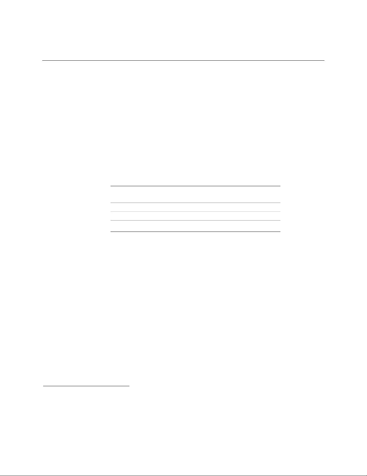
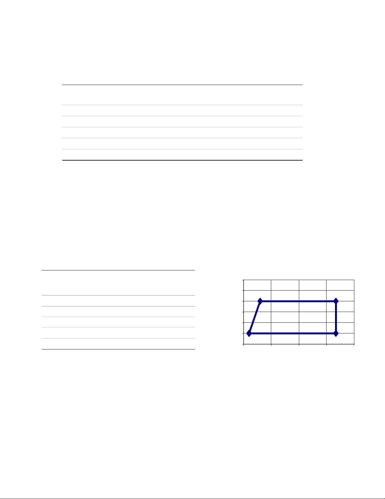
Table 6. Typical Power Distribution for a 160 W SFX12V Configuration
Output Minimum
Current
(amps)
+12 VDC 2.0 8.0 10.0
+5 VDC 0.3 12.0 (Note)
+3.3 VDC 0.5 16.7 (Note)
-12 VDC 0.0 0.3
+5 VSB 0.0 1.5 2.0
Note: Total combined output of 3.3 V and 5 V is < 61 W.
Maximum
Current
(amps)
Peak
Current
(amps)
12
10
8
6
4
12V Load (A)
2
0
0 5 10 15 20
5V + 3.3V Combined Load (A)
Page 12
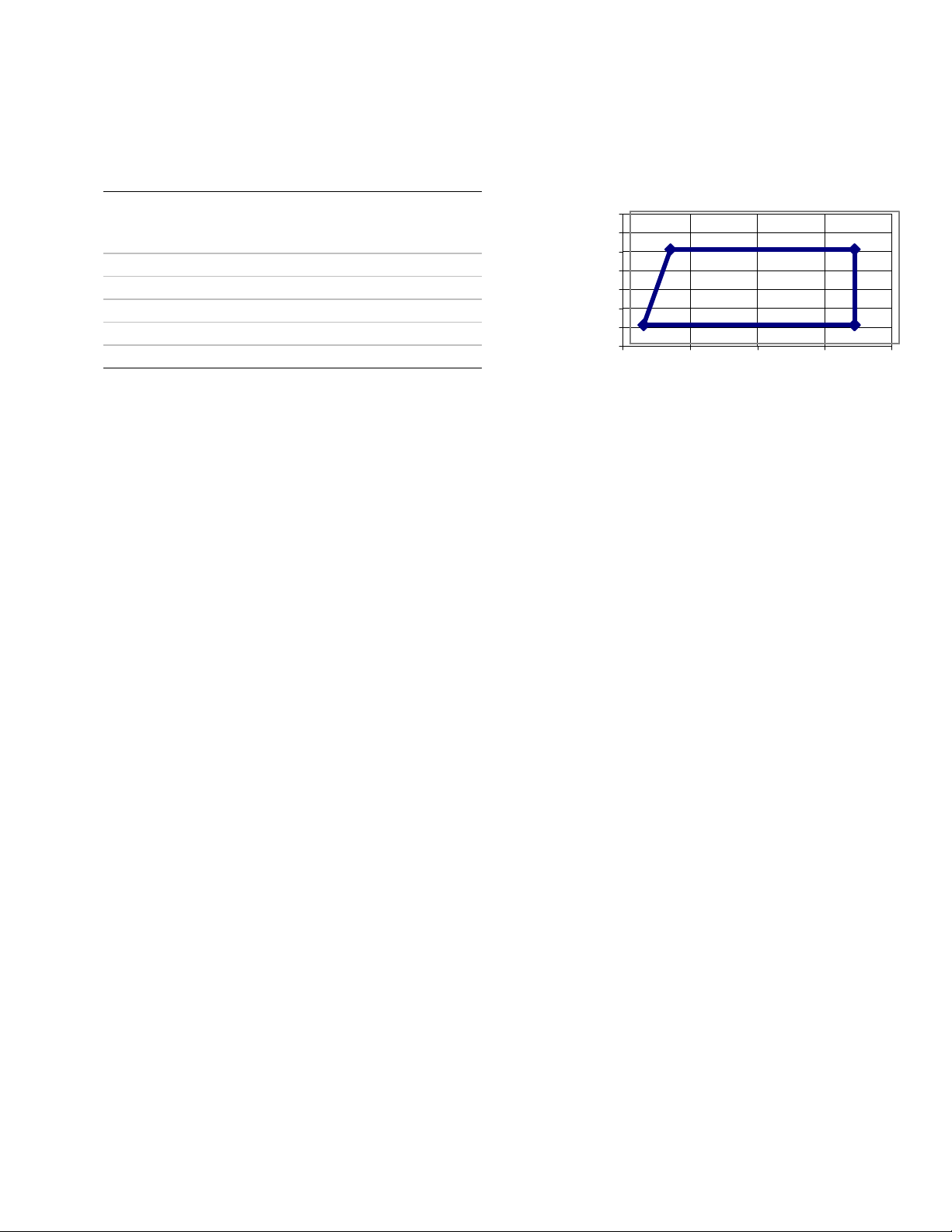
Table 7. Typical Power Distribution for 180 W SFX12V Configuration
Output Minimum
Current
(amps)
+12 VDC 2.0 10.0 13.0
+5 VDC 0.3 12.0 (Note)
+3.3 VDC 0.5 16.7 (Note)
-12 VDC 0.0 0.3
+5 VSB 0.0 1.5 2.0
Note: Total combined output of 3.3 V and 5 V is < 61 W
Maximum
Current
(amps)
Peak
Current
(amps)
SFX/SFX12V Power Supply Design Guide
Version 2.2
14
12
10
8
6
4
12V Load (A)
2
0
0 5 10 15 20
5V + 3.3V combined Load (A)
3.2.4. Power Limit / Hazardous Energy Levels
Under normal or overload conditions, no output shall continuously provide 240 VA under any
conditions of load including output short circuit, per the requirement of UL 1950/CSA 950 / EN
60950/IEC 950.
3.2.5. Efficiency
3.2.5.1. General
The power supply should be a minimum of 68% efficient under maximum rated load. The
efficiency of the power supply should be met over the AC input range defined in Table 1, under
the load conditions defined in Section 3.2.3, and under the temperature and operating conditions
defined in Section 7.
3.2.5.2. Energy Star
The “Energy Star” efficiency requirements of the power supply depend on the intended system
configuration. In the low-power / sleep state (S1 or S3) the system should consume power in
accordance with the values listed in Table 8.
Page 13

SFX/SFX12V Power Supply Design Guide
Version 2.2
Table 8 Energy Star Input Power Consumption
Maximum Continuous Power
Rating of Power Supply
RMS Watts from the AC line in
sleep/low-power mode
< 200 W < 15 W
> 200 W < 300 W < 20 W
> 300 W < 350 W < 25 W
> 350 W < 400 W < 30 W
> 400 W 10% of the maximum continuous output
rating
Note: To help meet the “Energy Star” system requirements, it is recommended that
the power supply have > 50% efficiency at light load and in standby mode.
3.2.5.3. Blue Angel, RAL-UZ 78
To help meet the Blue Angel system requirements, the +5 VSB standby supply efficiency should
be as high as possible. Standby efficiency is measured with the main outputs off (PS_ON# high
state). To meet Blue Angel system requirements, the AC input power shall not exceed 5 W when
the main outputs are in the “DC disabled” state with 500 mA load on +5 VSB and a 230 VAC /
50 Hz input.
3.2.6. Output Ripple/Noise
The output ripple/noise requirements listed in Table 9 should be met throughout the load ranges
specified in Section 3.2.3 and under all input voltage conditions as specified in Section 3.1.
Ripple and noise are defined as periodic or random signals over a frequency band of 10 Hz to
20 MHz. Measurements shall be made with an oscilloscope with 20 MHz bandwidth. Outputs
should be bypassed at the connector with a 0.1 µF ceramic disk capacitor and a 10 µF electrolytic
capacitor to simulate system loading. See Figure 1.
Table 9. DC Output Noise/Ripple
Output
+12 VDC 120
+5 VDC 50
+3.3 VDC 50
-12 VDC 120
+5 VSB 50
Maximum Ripple
and Noise
(mVpp)
Page 14

SFX/SFX12V Power Supply Design Guide
V out
V return
Version 2.2
Power Supply
AC Hot
AC Neutral
AC Ground
General Notes:
1. Load the output with its minimum load
current.
2. Connect the probes as shown.
3. Repeat the measurement with maximum
load on the output.
Filter Note:
0.1uf - Kemet, C1206C104K5RAC or equivalent
10uf - United Chemi-con, 293D106X0025D2T or
equivalent
10uf
0.1uf
Scope Note:
Use Tektronix TDS460 Oscilloscope or
equivalent and a P6046 probe or equivalent.
Load
Load must be
isolated from the
ground of the
power supply.
Scope
Figure 1. Differential Noise Test Setup
3.2.7. Output Transient Response
Table 10 summarizes the expected output transient step sizes for each output. The transient load
slew rate is = 1.0 A/µs.
Table 10. DC Output Transient Step Sizes
Output Maximum step size
(% of rated output amps per Sec 3.2.3)
(Note)
+12 VDC 50%
+5 VDC 30%
+3.3 VDC 30%
-12 VDC 0.1 A
+5 VSB 0.5 A
Note: For example, for a rated +5 VDC output of 14 A, the transient step would be 30% × 14 A = 4.2 A
Maximum. step
size (amps)
Page 15

SFX/SFX12V Power Supply Design Guide
Version 2.2
Output voltages should remain within the regulation limits of Table 2, Section 3.2.1 for
instantaneous changes in load as specified in Table 10 and for the following conditions:
• Simultaneous load steps on the +12 VDC, +5 VDC, and +3.3 VDC outputs (all steps
occurring in the same direction)
• Load-changing repetition rate of 50 Hz to 10 kHz
• AC input range per Section 3.1
• Capacitive loading per Table 11
3.2.8. Capacitive Load
The power supply should be able to power up and operate with the regulation limits defined in
Table 2, Section 3.2.1 with the following capacitances simultaneously present on the DC outputs.
Table 11. Output Capacitive Loads
Output Capacitive load (µF)
+12 VDC
+5 VDC
+3.3 VDC
-12 VDC
+5 VSB
5,000
10,000
6,000
350
350
3.2.9. Closed-loop Stability
The power supply shall be unconditionally stable under all line/load/transient load conditions
including capacitive loads specified in Section 3.2.8. A minimum of 45 degrees phase margin
and 10 dB gain margin is recommended at both the maximum and minimum loads.
3.2.10. +5 VDC / +3.3 VDC Power Sequencing
The +12 VDC and +5 VDC output levels must be equal to or greater than the +3.3 VDC output
at all times during power-up and normal operation. The time between the +12 VDC or +5 VDC
output reaching its minimum in-regulation level and +3.3 VDC reaching its minimum inregulation level must be ≤ 20 ms.
3.2.11. Voltage Hold-up Time
The power supply should maintain output regulation per Section 3.2.1 despite a loss of input
power at the low-end nominal range—115 VAC / 57 Hz or 230 VAC / 47 Hz—at maximum
continuous output load as applicable for a minimum of 17 ms.
Page 16

3.3. Timing / Housekeeping / Control
Figure 2. Power Supply Timing
Notes:
T1 is defined in Section 3.3.4.
T2 is defined in Section 3.3.5.
T3, T4, T5, and T6 are defined in Table 12
SFX/SFX12V Power Supply Design Guide
Version 2.2
3.3.1. PWR_OK
PWR_OK is a “power good” signal. This signal should be asserted high by the power supply to
indicate that the +12 VDC, +5 VDC, and +3.3 VDC outputs are above the under voltage
thresholds listed in Table 2 of Section 3.2.1 and that sufficient mains energy is stored by the
converter to guarantee continuous power operation within specification for at least the duration
specified in Section 3.2.11, “Voltage Hold-up Time.” Conversely, PWR_OK should be deasserted to a low state when any of the +12 VDC, +5 VDC, or +3.3 VDC output voltages falls
below its under voltage threshold, or when mains power has been removed for a time sufficiently
long such that power supply operation cannot be guaranteed beyond the power-down warning
time. The electrical and timing characteristics of the PWR_OK signal are given in Table 12 and
in Figure 2.
Page 17

SFX/SFX12V Power Supply Design Guide
Version 2.2
Table 12. PWR_OK Signal Characteristics
Signal Type +5 V TTL compatible
Logic level low < 0.4 V while sinking 4 mA
Logic level high Between 2.4 V and 5 V output while sourcing 200 µA
High-state output impedance
PWR_OK delay 100 ms < T3 < 500 ms
PWR_OK rise time
AC loss to PWR_OK hold-up time T5 ≥ 16 ms
Power-down warning T6 ≥ 1 ms
1 kΩ from output to common
T4 ≤ 10 ms
3.3.2. PS_ON#
PS_ON# is an active-low, TTL-compatible signal that allows a motherboard to remotely control
the power supply in conjunction with features such as soft on/off, Wake on LAN†, or wake-onmodem. When PS_ON# is pulled to TTL low, the power supply should turn on the four main
DC output rails: +12 VDC, +5 VDC, +3.3 VDC, and -12 VDC. When PS_ON# is pulled to
TTL high or open-circuited, the DC output rails should not deliver current and should be held at
zero potential with respect to ground. PS_ON# has no effect on the +5 VSB output, which is
always enabled whenever the AC power is present. Table 13 lists PS_ON# signal characteristics.
The power supply shall provide an internal pull-up to TTL high. The power supply shall also
provide de-bounce circuitry on PS_ON# to prevent it from oscillating on/off at startup when
activated by a mechanical switch. The DC output enable circuitry must be SELV-compliant.
The power supply shall not latch into a shutdown state when PS_ON# is driven active by pulses
between 10ms to 100ms during the decay of the power rails.
Table 13. PS_ON# Signal Characteristics
Parameter Minimum Maximum.
VIL, Input Low Voltage 0.0 V 0.8 V
IIL, Input Low Current (Vin = 0.4 V) -1.6 mA
VIH, Input High Voltage (Iin = -200 µA) 2.0 V
VIH open circuit, Iin = 0 5.25 V
Page 18

SFX/SFX12V Power Supply Design Guide
5.25 = Maximum Open-
Version 2.2
≤ 0.8 V
PS is
enabled
Hysteresis ≥ 0.3 V
0.8 2.0
PS_ON# Voltage
2.0 V
≥
PS is
disabled
Circuit Voltage
Disable
Enable
Figure 3. PS_ON# Signal Characteristics
3.3.3. +5 VSB
+5 VSB is a standby supply output that is active whenever the AC power is present. This output
provides a power source for circuits that must remain operational when the five main DC output
rails are in a disabled state. Example uses include soft power control, Wake on LAN, wake-onmodem, intrusion detection, or suspend state activities.
The +5 VSB output should be capable of delivering a minimum of 1.0 A at +5 V ± 5% to
external circuits. Because trends indicate a growing demand for standby power, it is
recommended that designs be scalable to 2.0 A to meet future needs. The power supply must be
able to provide the required power during a "wake up" event. If an external USB device
generates the event, there may be peak currents as high as 2.5 A lasting no more than 500 ms.
Over current protection is required on the +5 VSB output regardless of the output current rating.
This ensures the power supply will not be damaged if external circuits draw more current than
the supply can provide.
3.3.4. Power-on Time
The power-on time is defined as the time from when PS_ON# is pulled low to when the +12
VDC, +5 VDC, and +3.3 VDC outputs are within the regulation ranges specified in Section
3.2.1. The power-on time shall be less than 500 ms (T1 < 500 ms).
+5 VSB shall have a power-on time of two seconds maximum after application of valid AC
voltages.
3.3.5. Rise Time
The output voltages shall rise from ≤10% of nominal to within the regulation ranges specified in
Section 3.2.1 within 0.2 ms to 20 ms (0.2 ms ≤ T2 ≤ 20 ms).
There must be a smooth and continuous ramp of each DC output voltage from 10% to 90% of its
final set point within the regulation band, while loaded as specified in Section 3.2.3. The smooth
turn-on requires that, during the 10% to 90% portion of the rise time, the slope of the turn-on
Page 19

SFX/SFX12V Power Supply Design Guide
Version 2.2
waveform must be positive and have a value of between 0 V/ms and [Vout, nominal / 0.1] V/ms.
Also, for any 5 ms segment of the 10% to 90% rise time waveform, a straight line drawn between
the end points of the waveform segment must have a slope ≥ [Vout, nominal / 20] V/ms.
3.3.6. Overshoot at Turn-on / Turn-off
The output voltage overshoot upon the application or removal of the input voltage, or the
assertion/de-assertion of PS_ON#, under the conditions specified in Section 3.1, shall be less
than 10% above the nominal voltage. No voltage of opposite polarity shall be present on any
output during turn-on or turn-off.
3.3.7. Reset after Shutdown
If the power supply latches into a shutdown state because of a fault condition on its outputs, the
power supply shall return to normal operation only after the fault has been removed and the
PS_ON# has been cycled OFF/ON with a minimum OFF time of one second.
3.3.8. +5 VSB at AC Power-down
After AC power is removed, the +5 VSB standby voltage output should remain at its steady state
value for the minimum hold-up time specified in Section 3.2.11 until the output begins to
decrease in voltage. The decrease shall be monotonic in nature, dropping to 0.0 V. There shall
be no other perturbations of this voltage at or following removal of AC power.
3.4. Output Protection
3.4.1. Over Voltage Protection
The over voltage sense circuitry and reference shall reside in packages that are separate and
distinct from the regulator control circuitry and reference. No single point fault shall be able to
cause a sustained over voltage condition on any or all outputs. The supply shall provide latchmode over voltage protection as defined in Table 14.
Table 14. Over Voltage Protection
Output Minimum Nominal Maximum Unit
+12 VDC 13.4 15.0 15.6 Volts
+5 VDC 5.74 6.3 7.0 Volts
+3.3 VDC 3.76 4.2 4.3 Volts
3.4.2. Short-circuit Protection
An output short circuit is defined as any output impedance of less than 0.1 ohms. The power
supply shall shut down and latch off for shorting the +3.3 VDC, +5 VDC, or +12 VDC rails to
return or any other rail. Shorts between main output rails and +5 VSB shall not cause any
damage to the power supply. The power supply shall either shut down and latch off or fold back
Page 20

SFX/SFX12V Power Supply Design Guide
Version 2.2
for shorting the negative rails. +5 VSB must be capable of being shorted indefinitely, but when
the short is removed, the power supply shall recover automatically or by cycling PS_ON#. The
power supply shall be capable of withstanding a continuous short-circuit to the output without
damage or overstress to the unit (for example, to components, PCB traces, and connectors) under
the input conditions specified in Section 3.1.
3.4.3. No-load Operation
No damage or hazardous condition should occur with all the DC output connectors disconnected
from the load. The power supply may latch into the shutdown state.
3.4.4. Over Current Protection
Overload currents applied to each tested output rail will cause the output to trip before reaching
or exceeding 240 VA. For testing purposes, the overload currents should be ramped at a
minimum rate of 10 A/s starting from full load.
3.4.5. Over-Temperature Protection
As an option, the power supply may include an over-temperature protection sensor, which can
trip and shut down the power supply at a preset temperature point. Such an overheated condition
is typically the result of internal current overloading or a cooling fan failure. If the protection
circuit is non-latching, then it should have hysteresis built in to avoid intermittent tripping.
3.4.6. Output Bypass
The output return may be connected to the power supply chassis. The return will be connected to
the system chassis by the system components.
4. Mechanical
4.1. Labeling / Marking
The following is a non-inclusive list of suggested markings for each power supply unit. Product
regulation stipulations for sale into various geographies may impose additional labeling
requirements.
• Manufacturer information: manufacturer's name, part number, and lot date code, etc., in
human-readable text and/or bar code formats
• Nominal AC input operating voltages (100-127 VAC and 200-240 VAC) and current rating
certified by all applicable safety agencies (see Section 7)
• DC output voltages and current ratings
• Access warning text (“Do not remove this cover. Trained service personnel only. No user
serviceable components inside.”) in English, German, Spanish, French, Chinese, and
Japanese with universal warning markings
Page 21

SFX/SFX12V Power Supply Design Guide
Version 2.2
4.2. Airflow / Fan
The designer’s choice of a power supply cooling solution depends in part on the targeted end-use
system application(s). At a minimum, the power supply design must ensure its own reliable and
safe operation.
Fan location/direction. In general, exhausting air from the system chassis enclosure via a
power supply fan at the rear panel is the preferred, most common, and most widely
applicable system-level airflow solution. However, some system/chassis designers may
choose to use other to meet specific system cooling requirements.
Fan size/speed. The SFX series has 40 mm, 60 mm, and 80 mm fan options. The 40 mm
fan version is shown in Appendix A, Figure 5. Appendix B, Figure 7 details an 80 mm top
mounted fan version. Appendix C, Figure 10 features the 80 mm top mounted, reduced
depth fan for the SFX12V. The standard SFX has a 60 mm axial fan shown in Appendix
D, Figure 12. It is recommended that a thermally sensitive fan speed control circuit be used
to balance system-level thermal and acoustic performance. The circuit typically senses the
temperature of the secondary heatsink and/or incoming ambient air and adjusts the fan
speed as necessary to keep power supply and system component temperatures within
specification. Both the power supply and system designers should be aware of the
dependencies of the power supply and system temperatures on the control circuit response
curve and fan size and should specify them carefully.
The power supply fan should be turned off when PS_ON# is de-asserted (high). In this
state, any remaining active power supply circuitry must rely only on passive convection for
cooling.
Venting. In general, more venting in a power supply case yields reduced airflow
impedance and improved cooling performance. Intake and exhaust vents should be large,
open, and unobstructed as possible so as not to impede airflow or generate excessive
acoustic noise. In particular, avoid placing objects within 0.5 inches of the intake or
exhaust of the fan itself. A flush-mount wire fan grill can be used instead of a stamped
metal vent for improved airflow and reduced acoustic noise.
The limitations to the venting guidelines above are:
• Openings must be sufficiently designed to meet the safety requirements described in
Section 7.
• Larger openings yield decreased EMI-shielding performance (see Section 6).
• Venting in inappropriate locations can detrimentally allow airflow to bypass those
areas where it is needed.
4.3. AC Connector
The AC input receptacle should be an IEC 320 type or equivalent. In lieu of a dedicated switch,
the IEC 320 receptacle may be considered the mains disconnect.
Page 22

SFX/SFX12V Power Supply Design Guide
N/C
Version 2.2
4.4. DC Connectors
Figure 4shows pin outs and profiles for typical SFX power supply DC harness connectors. The
SFX12V requires an additional two-pin, power connector.
UL Listed or recognized component appliance wiring material rated min 85 °C, 300 VDC shall
be used for all output wiring.
There are no specific requirements for output wire harness lengths, as these are largely a function
of the intended end-use chassis, motherboard, and peripherals. Ideally, wires should be short to
minimize electrical/airflow impedance and simplify manufacturing, yet they should be long
enough to make all necessary connections without any wire tension (which can cause
disconnections during shipping and handling). Recommended minimum harness lengths for
general-use power supplies is 150 mm for all wire harnesses. Measurements are made from the
exit port of the power supply case to the wire side of the first connector on the harness.
SFX12V connector
Figure 4. SFX/SFX12V Connectors
(Pin-side view, not to scale)
Page 23

SFX/SFX12V Power Supply Design Guide
Version 2.2
4.4.1. SFX Main Power Connector
Connector: MOLEX 39-01-2200 or equivalent
(Mating motherboard connector is Molex 39-29-9202 or equivalent)
18 AWG is suggested for all wires except for the +3.3 V supply and sense return wires
combined into pin 11 (22 AWG).
Pin Signal Color Pin Signal Color
1 +3.3 VDC
2 +3.3 VDC Orange 12 -12 VDC Blue
3 COM Black 13 COM Black
4 +5 VDC Red 14 PS_ON# Green
5 COM Black 15 COM Black
6 +5 VDC Red 16 COM Black
7 COM Black 17 COM Black
8 PWR_OK Gray 18 Reserved NC
9 +5 VSB Purple 19 +5 VDC Red
10 +12 VDC Yellow 20 +5 VDC Red
Orange
11
[11]
+3.3 VDC
[+3.3 V default
sense]
Orange
[Brown]
Page 24

4.4.2. Peripheral Connector(s)
Connector: AMP 1-480424-0 or MOLEX
8981-04P or equivalent.
Contacts: AMP 61314-1 or equivalent.
Pin Signal 18 AWG Wire
1 +12 VDC Yellow
2 COM Black
3 COM Black
4 +5 VDC Red
4.4.3. Floppy Drive Connector
Connector: AMP 171822-4 or equivalent
Pin Signal 20 AWG Wire
1 +5 VDC Red
2 COM Black
3 COM Black
4 +12 VDC Yellow
SFX/SFX12V Power Supply Design Guide
Version 2.2
4.4.4. +12 V Power Connector (for SFX12V only)
Connector: MOLEX 39-01-2040 or equivalent
(Mating motherboard connector is Molex 39-29-9042 or equivalent)
Pin Signal 20 AWG Wire Pin Signal 20 AWG Wire
1 COM Black 3 +12 VDC Yellow
2 COM Black 4 +12 VDC Yellow
Page 25

SFX/SFX12V Power Supply Design Guide
Version 2.2
5. Environmental
The following subsections define recommended environmental specifications and test
parameters, based on the typical conditions to which an SFX and power supply may be subjected
during operation or shipment.
5.1. Temperature
Operating ambient +10 °C to +50 °C (At full load, with a maximum temperature rate of
change of 5 °C/10 minutes, but no more than 10 °C/hr.)
Non-operating ambient -40 °C to +70 °C (Maximum temperature rate of change of
20 °C/hr.)
5.2. Thermal Shock (Shipping)
Non-operating -40 °C to +70 °C
15 °C/min ≤ dT/dt ≤ 30 °C/min
Tested for 50 cycles; Duration of exposure to temperature
extremes for each half cycle shall be 30 minutes.
5.3. Humidity
Operating To 85% relative humidity (non-condensing)
Non-operating To 95% relative humidity (non-condensing)
Note: 95% RH is achieved with a dry bulb temperature of
55 °C and a wet bulb temperature of 54 °C.
5.4. Altitude
Operating To 10,000 ft
Non-operating To 50,000 ft
5.5. Mechanical Shock
Non-operating 50 g, trapezoidal input; velocity change ≥ 170 in/s
Three drops on each of six faces are applied to each sample.
Page 26

SFX/SFX12V Power Supply Design Guide
Version 2.2
5.6. Random Vibration
Non-operating 0.01 g²/Hz at 5 Hz, sloping to 0.02 g²/Hz at 20 Hz, and maintaining
0.02 g²/Hz from 20 Hz to 500 Hz. The area under the PSD curve is
3.13 gRMS. The duration shall be 10 minutes per axis for all three
axes on all samples.
5.7. Acoustics
Sound Pressure: The power supply assembly shall not produce a sound pressure level greater
than 40 db(A) in a 1/3 octave frequency band, when measured over the frequency range of 100 to
10 kHz at 35oC ambient at one half load. Sound pressure determination is to be performed in
accordance with ISO 7779.
Pure Tones: The maximum permissible sound pressure variation between adjacent 1/3 octave
bands may not exceed 10 db(A). Sound pressure determination to be performed in accordance
with ISO 7779
5.8. Ecological Requirements
The following materials must not be used during design and/or manufacturing of this product:
• Cadmium shall not be used in painting or plating.
• No Quaternary salt or PCB electrolytic capacitors shall not be used.
• CFC’s or HFC’s shall not be used in the design or manufacturing process.
• Mercury shall not be used.
Page 27

SFX/SFX12V Power Supply Design Guide
Version 2.2
6. Electromagnetic Compatibility
The following subsections outline applicable product regulatory requirements for the
SFX12/SFX12V power supply. Additional requirements may apply dependent upon the design,
product end use (e.g., medical equipment and hazardous locations), target geography, and other
variables.
6.1. Emissions
The power supply shall comply with FCC Part 15, EN22022: 1998 and CISPR 22, 3rd ed.,
meeting Class B for both conducted and radiated emissions with a 4 dB margin. Tests shall be
conducted using a shielded DC output cable to a shielded load. The load shall be adjusted as
follows for three tests: No load on each output; 50% load on each output; 100% load on each
output. Tests will be performed at 100 VAC 50Hz, 120 VAC 60 Hz, and 230 VAC 50 Hz
power. Additionally, for FCC certification purposes, the power supply shall be tested using the
methods in 47 CFR 15.32(b) and authorized under the Declaration of Conformity process as
defined in 47 CFR 2.906 using the process in 47 CFR 2.1071 through 47 CFR 2.1077.
6.1.2 Immunity
The power supply shall comply with EN 55024:1998 and CISPR 24 prior to sale in the EU
(European Union), Korea, and possibly other geographies
6.2. Input Line Current Harmonic Content
For sales in EU (European Union) the power supply shall meet the requirements of EN61000-3-2
Class D and the Guidelines for the Suppression of Harmonics in Appliances and General Use
Equipment Class D for harmonic line current content at full rated power. See Table 15 for the
harmonic limits.
Page 28

Table 15: Harmonic Limits, Class D equipment
Per: EN 61000-3-2 Per: JEIDA MITI
Harmonic Order
n
Odd harmonics
3
5
7
9
11
13
15≤ n ≤39
Maximum permissible Harmonic
current at 230 VAC / 50 Hz in Amps
2.3
1.14
0.77
0.4
0.33
0.21
0.15 x (15/n)
6.3. Magnetic Leakage Fields
SFX/SFX12V Power Supply Design Guide
Version 2.2
Maximum permissible Harmonic
current at 100VAC / 50 Hz in Amps
5.29
2.622
1.771
0.92
0.759
0.483
0.345 x (15/n)
A PFC choke magnetic leakage field should not cause any interference with a high-resolution
computer monitor placed next to or on top of the end-use chassis.
6.4. Reliability
The derating process promotes quality and high reliability. All electronic components should be
designed with conservative device deratings for use in commercial and industrial environments.
6.5. Mean Time Between Failures (MTBF)
The MTBF of the power supply can be calculated with the Part-Stress Analysis method of
MIL-HDBK-217F using the quality factors listed in MIL-HDBK-217F. A target calculated
MTBF of the power supply is greater than 100,000 hours under the following conditions:
• 75 % of Full-rated load
• 120 VAC input
• Ground benign
Page 29

SFX/SFX12V Power Supply Design Guide
Version 2.2
6.6. Voltage Fluctuations and Flicker
The power supply shall meet the specified limits of EN61000-3-3 for voltage fluctuations and
flicker for equipment drawing not more then 16AAC, connected to low voltage distribution
systems.
7. Safety
The following subsections outline sample product regulations requirements for a typical power
supply. Actual requirements will depend on the design, product end use, target geography, and
other variables. Consult your company’s Product Safety and Regulations department for more
details.
7.1. North America
The power supply must be certified by an NRTL (Nationally Recognized Testing Laboratory) for
use in the USA and Canada under the following conditions:
• The supply must be Recognized for use in Information Technology Equipment including
Electrical Business Equipment per UL 1950 / CAN/CSA C22.2 No. 950-95, renamed UL
60950, 3rd edition, without D3 deviations. The certification must include external enclosure
testing for the AC receptacle side of the power supply (see Appendix A, B, C, and D).
• The supply must have a full complement of tests conducted as part of the certification, such
as input current, leakage current, hi-pot, temperature, energy discharge test, transformer
output characterization test (open-circuit voltage, short-circuit current, and maximum VA
output), and abnormal testing (to include stalled-fan tests and voltage-select–switch
mismatch).
• The enclosure must meet fire enclosure mechanical test requirements per clauses 2.9.1 and
4.2 of the above-mentioned standard.
100% production hipot testing must be included and marked as such on the power supply
enclosure.
There must not be unusual or difficult conditions of acceptability such as mandatory additional
cooling or power derating. The insulation system shall not have temperatures exceeding their
rating when tested in the end product.
The certification mark shall be marked on each power supply.
The power supply must be evaluated for operator-accessible secondary outputs (reinforced
insulation) that meet the requirements for SELV and do not exceed 240 VA under any condition
of loading.
Page 30

SFX/SFX12V Power Supply Design Guide
Version 2.2
The proper polarity between the AC input receptacle and any printed wiring boards connections
must be maintained (that is, brown=line, blue=neutral, and green=earth/chassis).
Failure of any single component in the fan-speed control circuit shall not cause the internal
component temperatures to exceed the abnormal fault condition temperatures per IEC 60950.
7.2. International
The vendor must provide a complete CB certificate and test report to IEC 60950:1991, 2nd
edition + A1, A2, A3, and A4. The CB report must include ALL CB member country national
deviations. CB report must include evaluation to EN 60950:1992, + A1, A2, A3, A4 and Nordic
deviations EMKO-TSE (74-SEC) 207/94.
All evaluations and certifications must be for reinforced insulation between primary and
secondary circuits.
8. SYSTEM COOLING CONSIDERATIONS
The fan location allows the system designer to utilize the airflow to help cool critical
components such as the processor and chipset without adding a second system fan. This
will reduce acoustic noise and system cost. Please note that the fan pulls air from the
system, instead of blowing hot air into the system, so components must be placed such that
airflow is directed across critical components. Cables, etc must not impede airflow.
However, it should be noted that a processor active heat sink might still be necessary
because of the limited amount of airflow that this type of power supply can deliver. For
more information on system thermal design, please refer to www.formfactors.org
Page 31

SFX/SFX12V Power Supply Design Guide
Version 2.2
APPENDIX A GUIDELINES FOR A LOWER PROFILE PACKAGE
A.1 OVERVIEW
For applications requiring a lower profile, such as a network PC or slim desktop chassis,
the power supply PCB could be repackaged in an enclosure 50 mm in height. This would
allow an internal 40 mm fan to be installed for power supply cooling. This power supply
would differ only in the mechanical outline specifications.
A.2 PHYSICAL DIMENSIONS
The supply shall be enclosed and meet the physical outline shown in Figure 5.
A.3 FAN REQUIREMENTS
The fan will draw air from the computer system cavity pressurizing the power supply
enclosure. The power supply enclosure shall exhaust the air through a grill located on the
rear panel. See Figure 6. The movement of the fan to the computer system cavity is to help
limit the acoustic noise of the unit.
The fan will be 40 mm.
Page 32

85.0
SFX/SFX12V Power Supply Design Guide
Version 2.2
Notes:
1. Unless otherwise specified, all
dimensions are in mm.
Tolerance:
Whole No.: XX +/- 1
Decimal No.: X.X +/- 0.5
2. Do not scale drawing.
3. A stamped SM fan guard may
be used subject to approval.
40mm Fan
50.0
38.0
125.0
6.0
85.0
115/220
6.0
88.0
100.0
4.0X6
100.0
OP Wire Harness Location is at
manufacturer's discretion
Airflow
6.0
Venting holes
OPTIONAL to outside of
chassis
Airflow
No. 6-32 UNC-2B
Threaded Hole (3X)
31.8
Figure 5 40 mm Profile Mechanical Outline
Ø 4 x 3
25.3
8.5
29.8
34.3
46.0
38.0
4.0
Note: all features of P/S enclosure
that are outside bold cutout must be
flush with wiht P/S face. Flush mount
135° x 4
screws if necessary
R 5
4.0
14.5
88.0
96.0
Figure 6 Chassis Cutout
Page 33

SFX/SFX12V Power Supply Design Guide
Version 2.2
APPENDIX B GUIDELINES FOR A TOP MOUNT FAN PACKAGE
B.1 OVERVIEW
For applications requiring greater airflow directed 90° to the power supply
top cover, such as a microATX or mini-tower chassis, the power supply
PCB could be repackaged in an enclosure with an 80 mm fan mounted to
the top cover. This would provide greater flow of cooling air with better
directed cooling. This power supply would differ only in the mechanical
outline specifications.
B.2 PHYSICAL DIMENSIONS
The supply shall be enclosed and meet the physical outline shown in
Figure 7.
B.3 FAN REQUIREMENTS
The fan will draw air from the computer system cavity pressurizing the
power supply enclosure. The power supply enclosure shall exhaust the air
through a grill located on the rear panel. See Figure 8. Moving the fan to
the computer system cavity helps to limit the acoustic noise of the unit.
The fan will be 80mm.
To prevent damage to the fan during shipment and handling, the power
supply designer should consider recessing the fan mounting, as shown in
Figure 9.
Page 34

85.0
SFX/SFX12V Power Supply Design Guide
Version 2.2
OP Wire HarnessLocation is at
manufacturer's discretion
Notes:
1. Unless otherwise specified, all
dimensions are in mm.
Tolerance:
Whole No.: XX +/- 1
Decimal No.: X.X +/- 0.5
2. Do not scale drawing.
3. A stamped SM fan guard may
be used subject to approval.
125.0
63.5
51.5
95.8
17.1
6.0
15.0
45.5
115/220
59.0
100.0
12.0
11.0 X 5.0 cutout
clearance under cutout
4.0X6
6.0
minimum of 6.0 from
inside cover
80mm Fan
Airflow
9.0 X 3.2 cutout
clearance under cutout
minimum of 4.5 from
inside cover
No. 6-32 UNC-2B
Threaded Hole (3X)
31.8
Venting holes
OPTIONAL - to
outside of
chassis
Airflow
6.0
88.0
100.0
Figure 7 Top Mount Fan Profile Mechanical Outline
Page 35

SFX/SFX12V Power Supply Design Guide
Version 2.2
Ø 4 x 3
59.5
51.5
4.0
Note: all features of P/S enclosure
that are outside bold cutout must be
flush with wiht P/S face. Flush mount
screws if necessary
135° x 4
4.0
14.5
88.0
96.0
8.5
34.3
R 5
25.3
29.8
Figure 8 Chassis Cutout
Fan recessed into
top cover
17.1
63.5
Figure 9 Recessed Fan Mounting
Page 36

SFX/SFX12V Power Supply Design Guide
Version 2.2
APPENDIX C GUIDELINES FOR A REDUCED DEPTH, TOP MOUNT FAN
PACKAGE
C.1 OVERVIEW
For applications requiring greater airflow directed 90° to the power supply
top cover, such as a microATX or mini-tower chassis, with reduced depth,
the power supply PCB could be repackaged in an enclosure with an 80 mm
fan mounted to the top cover, with the length and depth dimensions rotated
90°. This provides greater flow of cooling air with better directed cooling.
This power supply would differ only in the mechanical outline
specifications.
C.2 PHYSICAL DIMENSIONS
The supply shall be enclosed and meet the physical outline shown in
Figure 10.
C.3 FAN REQUIREMENTS
The fan will draw air from the computer system cavity pressurizing the
power supply enclosure. The power supply enclosure shall exhaust the air
through a grill located on the rear panel. See Figure 11. Moving the fan to
the computer system cavity helps to limit the acoustic noise of the unit.
The fan will be 80 mm.
Page 37

SFX/SFX12V Power Supply Design Guide
Version 2.2
OP Wire Harness -
Location is at manufacturer's
discretion
125.0
11.0 X 5.0 cutout
clearance under cutout
minimum of 6.0 from
inside cover
100.0
59.0
63.5
51.5
12.0
17.1
15.0
6.0
9.0 X 3.2 cutout
clearance under cutout
minimum of 4.5 from
inside cover
Airflow
45.5
95.8
125.0
115/220
6.0
113.0
80mm Fan
No. 6-32 UNC-2B
Threaded Hole (3X)
31.8
AC Input Connector Location is at manufacturer's
discretion
Airflow
15.0
Mounting Tab
Optional
4.0X6
6.0
Notes:
1. Unless otherwise specified, all
dimensions are in mm.
Tolerance:
Whole No.: XX +/- 1
Decimal No.: X.X +/- 0.5
2. Do not scale drawing.
3. A stamped SM fan guard may
be used subject to approval.
Figure 10 Reduced Depth Top Mount Fan Profile Mechanical Outline
Page 38

Ø 4 x 3
SFX/SFX12V Power Supply Design Guide
Version 2.2
59.5
51.5
4.0
Note: all features of P/S enclosure
that are outside bold cutout must be
flush with wiht P/S face. Flush mount
screws if necessary
135° x 4
4.0
14.5
113.0
R 5
121.0
25.3
8.50
29.8
34.3
Figure 11 Chassis cutout
Page 39

SFX/SFX12V Power Supply Design Guide
Version 2.2
APPENDIX D GUIDELINES FOR A LOWER PROFILE PACKAGE
D.1 OVERVIEW
For applications using the standard SFX profile.
D.2 PHYSICAL DIMENSIONS
The supply shall be enclosed and meet the physical outline shown in
Figure 12.
D.3 FAN REQUIREMENTS
The fan will draw air from the computer system cavity pressurizing the
power supply enclosure. The power supply enclosure shall exhaust the air
through a grill located on the rear panel. See Figure 13. Moving the fan to
the computer system cavity helps to limit the acoustic noise of the unit.
The fan will be 60 mm.
Page 40

60mm Fan
9.0 X 3.2 Cutout
Clearance under
cutout minimum
4.5 from inside
cover
27.3
125.0
3.50
100.0
68.5
85.0
85.0
4.0X6
SFX/SFX12V Power Supply Design Guide
Version 2.2
OP Wire Harness Location is at manufacturer's
discretion
42.5
5.0
11.0 X 5.0 Cutout (2x)
Clearance under
cutout minimum 6.0
from inside conver
6.0
Venting holes
OPTIONAL - to
outside of
chassis
Notes:
1. Unless otherwise specified, all
dimensions are in mm.
Tolerance:
Whole No.: XX +/- 1
Decimal No.: X.X +/- 0.5
2. Do not scale drawing.
3. A stamped SM fan guard may
be used subject to approval.
115/220
63.5
51.5
6.0
6.0
88.0
100.0
No. 6-32 UNC-2B
Threaded Hole (3X)
31.8
Figure 12 60 mm Mechanical Outline
Page 41

SFX/SFX12V Power Supply Design Guide
Version 2.2
Ø 4 x 3
8.5
25.3
29.8
34.3
59.5
51.5
4.0
Note: all features of P/S enclosure
that are outside bold cutout must be
flush with wiht P/S face. Flush mount
screws if necessary
135° x 4
4.0
14.5
88.0
96.0
R 5
Figure 13 Chassis Cutout
Page 42
 Loading...