

Quick start guide
3U 16 disks iSCSI for High availablity RAID storage array
www.enhance-tech.com
E400 IP v.1.0
E400 IP
© Copyright 2009. Enhance Technology, Inc. Proudly Assembled in the U.S.A.
UltraStor Enterprise ES Series
L
Linux
Where Storage Begins
2
1
Thank you for choosing Enhance Technology
Carefully unpack your E400 IP storage system, and inventory the
accessories according to your model type.
What is in the box?
3
Unpack all components including the HDD mounting screws, key sets and
cables. If you are missing any of the items mentioned above, please contact
your dealer or contact Enhance Technology at www.enhance-tech.com.
Unpack your E400 IP
Welcome
Thank you for buying Enhance Technology E400 Series, a compact dual GbE
iSCSI RAID storage system with a slick T shaped tray design, built in next
generation hardware RAID controller, and a standard 300 watts 80+ green
power supply.
E400 IP
Quick start guide
ENHANCE|TECHNOLOGY
Standard IEC Power Cable - Qty 2
HDD Mounting Hardware - Qty 32
Hot-swap Disk Trays - Qty 8
8 disks iSCSI for Energy Ecient Desktop Productivity RAID
User Guide and CD- Qty 1
Quick start guide
3U 16 disks iSCSI for High availablity RAID storage array
www.enhance-tech.com
E400 IP v.1.0
E400 IP
© Copyright 2009. Enhance Technology, Inc. Proudly Assembled in the U.S.A.
UltraStor Enterprise ES Series
L
Linux
4
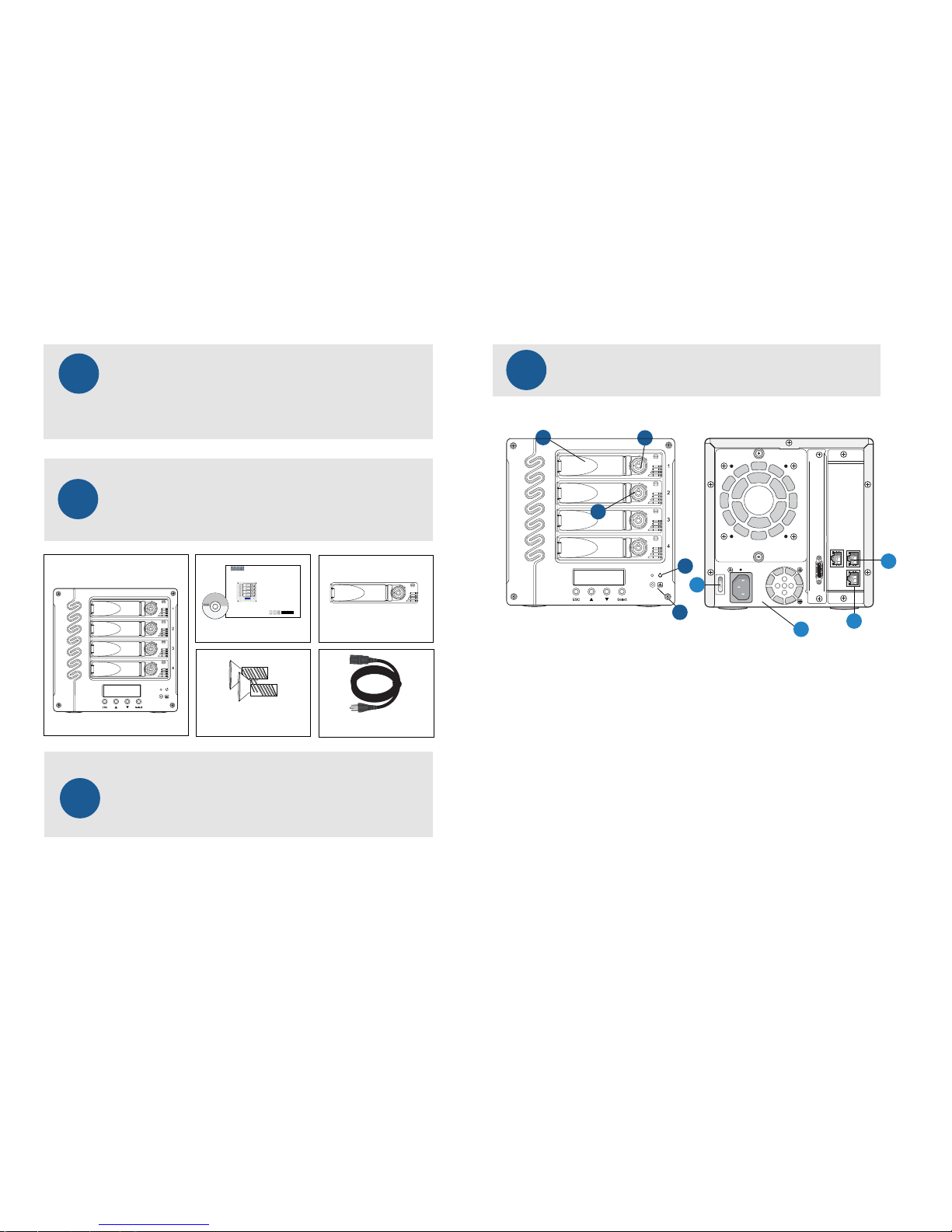
Understanding your E400 IP
Learn and identify each component of E400 IP
Front:
1. Security Key Lock
2. Hot-swap HDDs Tray
3. Power LED
4. HDD Active LED
5. Fan Error LED
Rear:
6. Power Switch
7. Power Supply
8. Web GUI Management Console
9. Dual GbE iSCSI Ports
1
3
2
5
9
7
7
6
4

E400 IP
5
Disk Installation
If your system was purchased with capacity, please skip this section and
immediately go to next section. If your system was purchased without disks,
install each disk into the provided disk trays and fasten using the supplied
hdd screws. Do not use any other mounting screws other than the ones provided
with your system. System or disk damage may occur if using non-approved
mounting hardware.
Hard Disk
+
+
+
+
Figure 1. Figure 2.
Disk tray - Bottom view
Disk Tray
6
Figure 7.
Insert Disk Module
After fastening each disk, insert the disk trays in the open disk bay on your
system. For added security, your system is equipped with locking
disk bays to prevent accidental or malicious disk removal.
Quick start guide
ENHANCE|TECHNOLOGY
8 disks iSCSI for Energy Ecient Desktop Productivity RAID
7
Connecting Your E400 IP - Cable Connections
- Option 1
Direct connect to the host computer with iSCSI cables.
Ensure that all of the connectors are properly secured & fastne]d. Most commom
issues are related to poor cable connection. Do not force connector into place.
Figure 8.
Host Computer
GbE iSCSI Ports
GbE iSCSI Cables
Gently “press” tray handle to insert HDD

E400 IP
Ethernet Switch
Quick start guide
ENHANCE|TECHNOLOGY
9
Figure 10.
Figure 11.
10
After connecting both data and Web GUI cables to your system and host
computer, power-on your E400 rst, then power-on your host computer.
Your array is now ready for RAID conguration in the Web GUI.
Power On
Connecting Your E400 IP - Web GUI Connection
Connect E400 Web GUI console to the host computer on the network with
cross over cable or connect to the Ethernet switch with LAN cable
then power on the system.
Web GUI Console
Ethernet Switch
Host Computer
On O
WARNING: To minimize the chance of
electrical shock, always follow proper
safety rules when working with
electrical materials.
8
Connecting Your E400 IP - Cable Connections - Option 2
Connect to the host computer via Ethernet Switch with iSCSI cables.
Ensure that all of the connectors are properly secured & fastned. Most commom issues are related to poor cable connection. Do not force connector into place.
Figure 9.
Host Computer
GbE iSCSI Ports
GbE iSCSI Cables
8 disks iSCSI for Energy Ecient Desktop Productivity RAID

E400 IP
Quick start guide
ENHANCE|TECHNOLOGY
1. System is booting up when turn on the power.
2. RAID controller is initializing the system to check
the hardware connection and memory. This is NOT
initializing for the hard disks.
3. The system has booted up successfully and showing
the system IP address on the LCD screen.
Now you can login Web GUI to create a RAID Array for
your TS800
11
Preparing E400 IP for Conguration
After power-on, the power LED and hard disks LEDs will light up and your E400
will display a message showing the system is booting then change to Initializing
mode for few seconds to check the system.
192.168.0.200
Enhance Technology
System Booting
Initializing
................................
13
You will be using the Quick Install function in the Web GUI to create a RAID and
User Data Volume for your E400.
Create a RAID Array
NOTE: The Quick Install function is designed for set up a single RAID level with a single User Data Volume. If you
want to congurate your system with multiple RAID levels with multiple User Data Volumes please learn from
system User Manual CD for complete instructions.
NOTE: Depending on the capacity of your system. The RAID array initialization process may take several minutes.
Please allow plenty of time for this process. Never turn o your TS800 while initializing the array.
Step 1: Select Quick Install then choose the RAID Level desired. After
choosing the RAID level, click NEXT.
Step 2: In this step, the volume can be customized as needed. Volume
size, Bus ID, SCSI ID, and LUN can be assigned specied numbers to be
attributed to the volume. The maximum volume size is shown as default.
The volume can only be less or equal to the number shown. By default,
the Bus ID, SCSI ID, and LUN are set at 0. Click NEXT after desired volume
size and IDs are set.
Step 3: Conrm if all the setting are correct then click Conrm to
nish the setup.
Done: A summary page with the User data volume will be shown:
A RAID 0 user data volume with the UDV name “QUICK86975”, named
by the system itself, with the total available volume size 222GB.
Figure 14.
Figure 12.
14
12
Login Web GUI
To access Web GUI utility, lanuch the web browser on your computer and enter the
E400’s IP address in the address eld.
Login Name: admin Password: 1234
NOTE: By default, the Web GUI’s network connection
type is set to Automatic conguration - DHCP, which
should be kept only if your network supports DHCP or
you are connecting through a dynamic IP address.
The TS2060’s IP address should be seen on the screen of
the controller. By default the IP address is 192.168.0.200
If you are required to use a permanent IP address, you
need to set a static IP address for the system.
(Please refer to User Manual CD for detail infomation)
Web GUI Sreen View
192.168.0.200
Enhance Technology
Figure 13.
8 disks iSCSI for Energy Ecient Desktop Productivity RAID

Congure iSCSI:
1. Open /etc/iscsi.conf le, enter:
# vi /etc/iscsi.conf
2. Setup it as follows:
3. Start the iscsi service
Type the following command to start iscsi
service so that you can see block device:
# chkcong iscsi on
# /etc/init.d/iscsi start
4. Run any one of the following to nd out new
block device name:
# fdisk -l
# tail -f /var/log/messages
# nd /sys/devices/platform/host* -name "block*"
16
Please refer to your computer’s documentation for detailed information on
formatting and preparing volumes for use
Format Volume for Linux OS
E400 IP
8 disks iSCSI for Energy Ecient Desktop Productivity RAID
Quick start guide
ENHANCE|TECHNOLOGY
14
To format the drive for Windows OS
1. Click on Control Panel, Performance and Maintenance, Administrative Tools.
2. Click on the Computer Management icon.
3. Click on the Disk Management Icon.
4. Right click on the new drive’s icon in the right hand window
5. Select the Format option, click yes in warning window.
6. Type a name for the drive under volume label.
7. Select perform quick format option.
8. Click OK in format warning box.
9. The drive will be formatted and available in My Computer and Windows Explorer.
Please refer to your computer’s documentation for detailed information on
formatting and preparing volumes for use
Format Volume for Windows OS
17
Connection Problems:
Always double check for loose cable connections or improperly seated disks
if you experience problems where a disk or volume does not appear in your
computer, or you recieve an error message stating a disk missing
when you have the drives congured as a RAID set.
1. Disconnect the data cables and reconnect each cable one at a time,
ensuring each connector is screwed in securely on your system.
2. Make sure the connector is properly secured on your HBA.
3. Check your TS800 IP’s drive presence LEDs, located on the front
panel of the system. If the LEDs are not lit, remove the disk and
reinsert the disk module.
If the problem persists, please contact your dealer or contact Enhance’s support department
at support@enhance-tech.com
This section covers some common support questions.
If you are experiencing an urgent issue, please contact
your dealer or call 1-562-777-3488 ex 119.
Troubleshooting
15
To format the drive for Mac OS
1. Go to the Applications folder on your system hard drive.
2. Open the Utilities folder.
3. Double click on the Disk Utility Program.
4. Find the drive in the left hand window and select the drive.
5. Click on the Partition tab.
6. Under Volume Scheme select 1 Partition
7. Type a name for the drive in the box provided.
8. Select Mac OS extended under the format options.
9. Click on Partition in the Partition dialog box.
10. The drive will be formatted and mounted on the desktop.
Please refer to your computer’s documentation for detailed information on
formatting and preparing volumes for use
Format Volume for Mac OS
DiscoveryAddress=ISCSI_TARGET_HOST_OR_IP
OutgoingUserName=ISCSI_USER_NAME
OutgoingPassword=ISCSI_PASSWORD
LoginTimeout=15
Then, save and close the le
5. Format iSCSI device
Use fdisk and mkfs.ext3 commands. First,
create a partition (assuming that /dev/sdc
is a new block device assigned to iscsi) :
# fdisk /dev/sdc
# mkfs.ext3 /dev/sdc1
Create /mnt/iscsi directory:
# mkdir -p /mnt/iscsi
Open /etc/fstab le and append cong
directive:
/dev/sdc1 /mnt/iscsi ext3 _netdev 0 0
Save and close the le. Mount the
parition /dev/sdc1:
# mount -a
# df -H
 Loading...