

Page 1

M
o
d
M
o
d
ell
e
1
1
EExxppeerriim
meenntteerr’’ss SSEE AAuuddiioo AA
UUsseerr’’ss MMaannuuaall
500-0001MR4
http://audio.engineeringvista.com Rev. 4
mpplliiffiieerr
m
Page 2

Dear Customer
We at ENG Vista want to take this opportunity to thank you for purchasing the Model 1
Experimenter’s SE Audio Amplifier. The people that stand behind your amplifier draw on more
than a decade of professional electronics design and manufacturing experience. We are
committed to providing our customers with the high quality sound at an affordable price. We have
achieved this goal through modern design, quality parts, expert components sourcing and efficient
manufacturing. We are confident that your amplifier will be a pleasure to experiment with and that
you will gain a valuable experience. When you are ready to move to the next stage in your
experimental work, the Model 1 will give you many years of listening pleasure as a part of your
audio system.
Before using this amplifier, please take the time to carefully read and understand the safety
instructions and operating procedures. Becoming familiar with all details about your amplifier will
ensure safe usage and reliable operation. Take special care when operating with high voltages
and making adjustments.
The effort you invest now will be well rewarded as the time goes by.
THANK YOU!
ENG Vista, Inc.
YOUR SAFETY IS VERY IMPORTANT TO US. PLEASE READ CAREFULLY THE
FOLLOWING NOTES AND SAFETY PRECAUTIONS. THANK YOU.
This kit is not intended for beginners. It requires familiarity with safe
procedures for tests, measurements and modifications of high voltage
equipment.
Exercise extreme caution when working with high voltages and always unplug
the power before making any changes or adjustments
NOTE: Please make sure to check our website at http://audio.engineeringvista.com for updates,
test results and latest news. On our website you can also order spare parts. Feel free to contact
us with any questions or comments. We are looking forward to hearing from you.
.
2
Page 3

SAFETY PRECAUTIONS
IMPORTANT SAFEGUARDS
PLEASE READ CAREFULLY ALL THE FOLLOWING
IMPORTANT SAFEGUARDS THAT ARE APPLICABLE
TO YOUR EQUIPMENT
SAFETY
1. Read the User’s Manual and refer to it frequently during your experimenting.
2. Retain the User’s Manual for future reference.
3. All warnings should be strictly adhered to.
4. Follow instructions to the last detail.
5. This product should be operated using only the type of power source indicated in this
manual.
6. Always use an electrical outlet that is grounded. If you do not know whether the outlet is
grounded, consult your electrician or local power company.
7. For continued protection against fire hazard, replace fuses with the same type and rating of
the fuses specified. When changing fuses, completely remove power from the circuit.
8. Power supply cords and all connecting cables or wires should be routed so that they are
not likely to be walked on or pinched. Pay particular attention to cords and cables at plugs,
receptacles and terminal blocks. Always use wires with adequate ratings and safety
certifications (CE, UL, etc.)
9. During operation the tubes get very hot. Do not touch the tubes since this may result in a
severe burn. Allow several minutes after removing power for tubes to cool down before
touching them.
10. Turn off the unit as soon as you stop actively using it. Unplug the power supply from the
wall during a lightning storm or when the product is to be left unattended and unused for
longer periods of time.
11. Do not use this product near water or in wet areas. Damp basements should be avoided.
12. The product should be placed away from heat sources such as radiators, heaters, stoves
or other appliances that produce heat. Also avoid putting the unit in the direct rays of the
Sun.
13. Proper ventilation is crucial for safe and reliable operation. Never place anything on top of
your amplifier that could obstruct airflow and cause the parts to overheat and damage the
amplifier. Do not place your amplifier in a rack or bookcase unless proper ventilation is
provided.
14. Care should be taken to prevent objects from falling and liquids from spilling into the unit.
Do not subject the unit to excessive smoke, dust, vibration or shock.
15. During experimenting, make sure that all jumpers are properly seated in the correct
position, that there are no foreign objects or solder bridges.
16. Always wear protective glasses and exercise caution when powering unit after any change
is made. If possible, gradually rise input voltage and look for any abnormalities – smell or
smoke, tubes overheating (excessive glow), etc.
3
Page 4

17. Unplug this product from the wall outlet before making any changes. Wait until tubes have
cooled down.
18. When using replacement parts, be sure to use parts with sufficient voltage and power
rating and adequate current carrying capability.
19. Should it become necessary to replace your tubes, remove the AC power plug from the
wall and allow thirty minutes for the high voltage capacitors to discharge.
20. If you have any questions regarding safe and reliable operation of your amplifier, please
email us at [email protected]
4
Page 5

GETTING STARTED
The Model 1 amplifier kit was designed to provide:
1. a universal tube amplifier suitable for everyday listening to the music from your PC or
portable music source, or as a guitar amplifier easy to overdrive;
2. a headphone amplifier;
3. an amplifier for familiarizing with the sound of Single Ended (SE) configuration;
4. a platform for experimenting with different variations of an SE topology: pentode, triode or
ultralinear operation, open loop or negative feedback, parallel tubes, etc.;
5. a significant value based on a high performance to price ratio.
The Model 1 is built on a two sided printed circuit board (PCB) and uses PCL82 (16A8) tubes
which are specifically designed for audio applications. If you bought assembled kit rest assured
that all amplifiers go through rigorous testing and extended burn-in before being shipped, so you
are guaranteed to receive high quality product.
There are two versions of the Model 1 amplifier kit:
1. BASIC: this amplifier will output 2-2.5W per channel in pentode mode (depending on the
output transformer selected) and comes with single stereo input and one pair of tubes. It is
best suited as a headphone amplifier or PC amplifier. An upgrade kit is available for
conversion to the FULL-PACK version.
2. FULL PACK: this version has maximum output power of 4-5W (depending on the output
transformer), has two stereo inputs and two pairs of tubes (the two tubes per channel are
connected in parallel). It is best suited for listening in small rooms and as an instrument
amplifier.
Due to the relatively low power, the Model 1 works best with efficient speakers (SPL above
90dBm). As every other SE amplifier, the Model 1 has a low damping factor – it will perform best
with single-driver Hi-Fi speakers or, alternatively, two-way speakers with simple crossovers.
The standard unit is delivered as an unassembled kit or tested and burned-in basic assembly.
Vacuum tubes are delivered separately in original boxes, for maximum protection. The tubes need
to be inserted and firmly seated in their sockets before the power is delivered to the unit.
The optimum sound reproduction will occur after 50-100 hours of operation. In normal use, upon
power-up, the unit needs to warm up for about 30 minutes for maximum performance.
The Model 1 kit does not include output transformers or power supply, unless it is specifically
listed that it does. Output transformers and power supply are separately sold.
5
Page 6

ASSEMBLING THE KIT
If you purchased an unassembled kit, you will have all the parts, including tubes and printed circuit
board. Parts are in marked bags, with reference numbers and value written on a bag. Reference
numbers are the ones printed on the PCB, so locating parts positions should be very easy. PCB
layout printout is also part of this document and you can use it to locate parts. Output transformers
are purchased separately, and not included in the kit.
First step is to review all the materials received, compare to the part list and prepare all tools and
a well lit work area. Tools that you need are very basic – soldering iron, tweezers or flat pliers, and
cutters. You will also need solder wire and a digital multimeter. If you have an oscilloscope, that
will help in final testing and experiments, but it is not necessary.
- Start assembly with filament configuration jumpers, configuring heaters for your specific
application.
- Follow with resistors, keeping in mind that resistors should be slightly elevated off the PCB
(1/32” is sufficient). Main reason is that power resistors get warm and this will help air circulation
and prevent overheating. Also, some resistors have circuit connections underneath and there is a
possibility of malfunction if the resistor body touches exposed trace. This is not very likely, since
the PCB connections are protected by a solder mask and resistors have durable coating.
However, this could be a matter of safety and, also, troubleshooting of such problems is really
difficult, so it is better to spend some extra time up front to come up with great assembly.
- After resistors, install 2x2 headers for mode selection (Pentode, Triode, Ultralinear, FBK, etc.).
- Next step is assembly of all capacitors. Make sure to follow polarity directions for electrolytic
capacitors. All electrolytics have markings designating leads to be connected to the negative
voltage. Model 1 printed circuit board has a plus sign for the positive terminal of an electrolytic
capacitor. Positive terminal on the PCB also has a square pad around the hole, for easier
identification on the bottom of the board.
- After capacitors are installed you can proceed with connectors and, finally, with tube sockets and
volume control potentiometers.
Once everything is installed, take a short break and then come back and carefully inspect your
work. Check component locations and proper orientation of electrolytic capacitors. Inspect all
solder joints and make sure there are no solder bridges or splashes on the board. All joints should
look clean and shiny. If you are not sure that a solder joint look right, touch it with a hot soldering
iron again, until it looks right. Cold solder joints may create problems few hours (days, months)
down the road and are extremely difficult to troubleshoot.
Then, plug in the tubes, connect the output transformers and speakers (or dummy loads) and
proceed with slowly powering up the unit.
Bring the power for the filaments (Vf) first and make sure that all the tubes have about 16V on
their heater pins (depending on your supply, it may take up to a minute for this voltage to
stabilize). You should be able to see nice yellow/orange glow from the heaters.
Tubes that you received are already burned-in, so you can continue by bringing anode voltage
(Va) and measuring the most important in-circuit voltages (refer to the schematics section for test
points and voltage levels). If you followed all the instructions, everything should go smoothly and
now you can connect some music source to the inputs and start enjoying fruits of your hard work.
But, for now, keep reading the instructions…..
6
Page 7

CONNECTIONS
NOTE: Before you turn the amplifier on, make sure the speaker connections are properly
hooked up, or that headphone selector switch is in the headphone position. Never run the
amplifier without speakers or headphones, since this may damage transformers. When
turning the unit on, make sure the volume control is at its lowest setting.
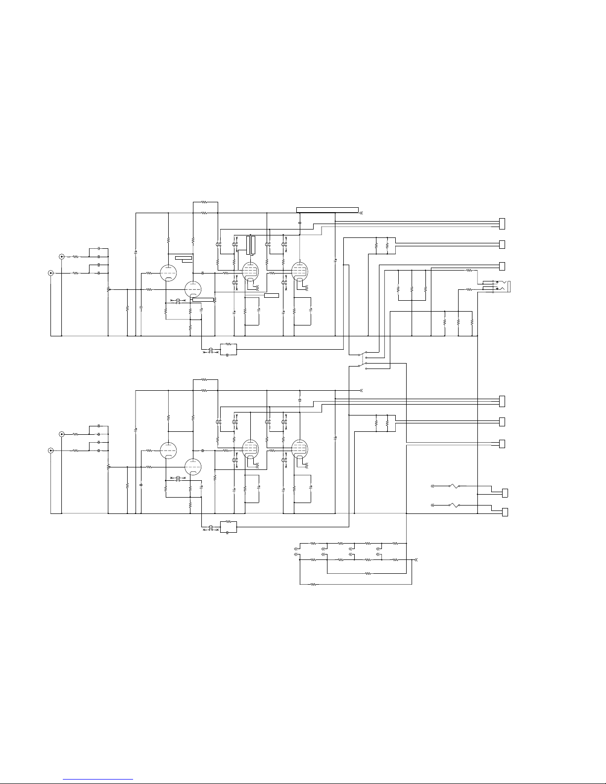
ELECTRICAL SCHEMATICS:
The complete electrical schematics with component values is given to assist you in your
experiments. Please note that the schematics is considered a copyrighted work and a trade
secret. However, as a purchaser of our product you are granted a license for unlimited
modifications. The only thing we ask for is that this schematics is not reprinted for public use or
commercially used without getting appropriate license from ENG Vista, Inc.
7
Page 8
8
Vf
PHONES
Vf4b
R82
220k/0.5W
202-0001
Vf4a
C132
10u/350V
100-0001
R252
27R/2W
206-0002
R51
1k
200-0003
J102
161-0001
12
34
R290
0R
N/A
R22
*1k*
200-0001
Vf3a
R201
*1k*
200-0003
C111
**220u/35V**
100-0002
R251
27R/2W
206-0002
R112
100R
200-0005
UL
C72
1n/50V
100-0003
Vf2a
C51
100n/250V
100-0006
J22
*RCA-WHITE*
160-0002
R52
1k
200-0003
OPT PRIM LEFT
T
C62
220u/35V
100-0002
R261
27R/2W
206-0002
R241
1k
200-0003
R131
100R
200-0005
OPT SEC LEFT
R182
1k
200-0006
J21
*RCA-RED*
160-0001
R91
*2k2*
200-0004
UL
Vf1b
C91
**220u/35V**
100-0002
SPEAKER LEFT
R340
*0R*
N/A
C41
10u/350V
100-0001
R271
27R/2W
206-0002
J172
161-0001
1 2
3 4
V4A
*PCL82*
990-0001
1
9
8
R92
*2k2*
200-0004
P
Va
V3B
*PCL82*
990-0001
4 52
7
3
6
R211
*100R*
200-0005
R392
*1k*
200-0003
PLATE
C101
*10u/350V*
100-0001
J121
161-0001
12
34
R142
1k
200-0003
FBK
V1B
PCL82
990-0001
4 52
7
3
6
J112
161-0001
12
34
V2B
PCL82
990-0001
4 52
7
3
6
Vf1b
R151
470k
200-0007
R71
*220k/0.5W*
202-0001
C121
1n/500V
100-0004
FILAMENT
95-110V
Va
V1A
PCL82
990-0001
1
9
8
R11
1k
200-0001
Vf3a
R272
27R/2W
206-0002
V4B
*PCL82*
990-0001
4 52
7
3
6
Vf4b
R350
*0R*
N/A
R221
*510R/2W*
206-0001
R81
220k/0.5W
202-0001
R62
*1k*
200-0003
R281
47R/1W
204-0001
P12
50k, audio
209-0002
Vf2b
C112
**220u/35V**
100-0002
J62
CONN PCB 2
160-0004
1
2
P
1.20-1.45V
R391
*1k*
200-0003
R121
1k
200-0003
SPEAKER RIGHT
Vf2b
C61
220u/35V
100-0002
J51
CONN PCB 2
160-0004
1
2
J42
CONN PCB 3
160-0003
1
2
3
C102
*10u/350V*
100-0001
FBK
240-245V
C122
1n/500V
100-0004
F20
3A
170-0002
P11
50k, audio
2209-0002
J161
161-0001
1 2
3 4
C92
**220u/35V**
100-0002
R111
100R
200-0005
UL
R202
*1k*
200-0003
R171
*22k/0.5W*
202-0002
R161
22k/0.5W
202-0002
Va
R132
100R
200-0005
R122
1k
200-0003
J11
RCA-RED
160-0001
R141
1k
200-0003
C22a
*100n/250V*
100-0006
R181
1k
200-0006
V3A
*PCL82*
990-0001
1
9
8
OPT SEC RIGHT
T
235-249V
J111
161-0001
12
34
J41
CONN PCB 3
160-0003
1
2
3
R300
*0R*
N/A
OPT PRIM RIGHT
C131
10u/350V
100-0001
R262
27R/2W
206-0002
R101
2k2
200-0004
R231
1k
200-0003
NOTES:
1. Parts with values between asterisks (*1k*, etc.) are used in the Full-Pack assembl;y;
2. C91,C92,C111 and C112 are not used.
J8
PHONEJACK STEREO SW
160-0005
3
5
4
2
1
C11
100n/250V
100-0006
J12
RCA-WHITE
160-0002
C52
100n/250V
100-0006
R41
N/U
R212
*100R*
200-0005
R320
*0R*
N/A
16-19V
J152
161-0001
12
34
Vf4a
R330
*0R*
N/A
J52
CONN PCB 2
160-0004
1
2
R192
510R/2W
206-0001
Vf
J162
161-0001
1 2
3 4
Vf3b
Vf3b
R152
470k
200-0007
R232
1k
200-0003
R61
*1k*
200-0003
T
Vf2a
R191
510R/2W
206-0001
C12
100n/250V
100-0006
J141
161-0001
12
34
R310
*0R*
N/A
J80
CONN PCB 2
160-0004
1
2
P
R72
*220k/0.5W*
202-0001
R222
*510R/2W*
206-0001
C22
*100n/250V*
100-0006
R172
*22k/0.5W*
202-0002
Vf1a
R42
N/U
R370
0R
N/A
C142
470p
100-0007
SW1
SW DPDT
180-0001
2
1
3
5
4
6
R282
47R/1W
204-0001
J101
161-0001
12
34
J131
161-0001
12
34
C81
10u/350V
100-0001
R380
0R
N/A
R12
1k
200-0001
C12a
100n/250V
100-0006
UL
R242
1k
200-0003
C21
*100n/250V*
100-0006
R102
2k2
200-0004
C21a
*100n/250V*
100-0006
J171
161-0001
1 2
3 4
J122
161-0001
12
34
C11a
100n/250V
100-0006
C82
10u/350V
100-0001
R360
*0R*
N/A
V2A
PCL82
990-0001
1
9
8
J151
161-0001
12
34
C141
470p
100-0007
T
R21
*1k*
200-0001
R162
22k/0.5W
202-0002
All measurements at Va=250V
C71
1n/50V
100-0003
F10
500mA
170-0001
J61
CONN PCB 2
160-0004
1
2
J142
161-0001
12
34
C42
10u/350V
100-0001
J90
CONN PCB 2
160-0004
1
2
J132
161-0001
12
34
P
Vf1a
Page 9

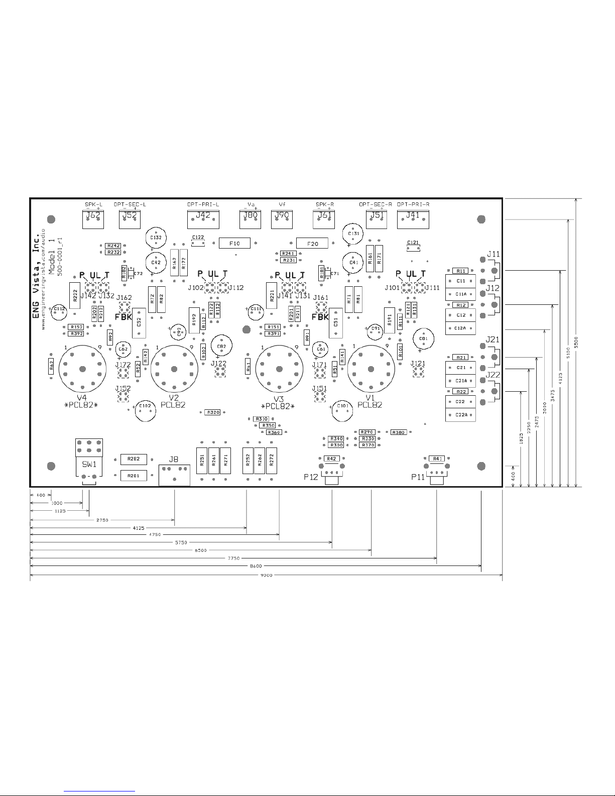
BOARD LAYOUT AND DIMENSIONS:
The following Figure shows the component layout and dimensions of the board (in mils –
1mil=0.001inch), mounting holes and locations of tubes, potentiometers, switch and headphone
connector, as well as locations of input jacks. This should help builder with designing a fitting
enclosure. Please always verify dimensions by measuring the actual printed circuit board.
9
Page 10
10
Page 11
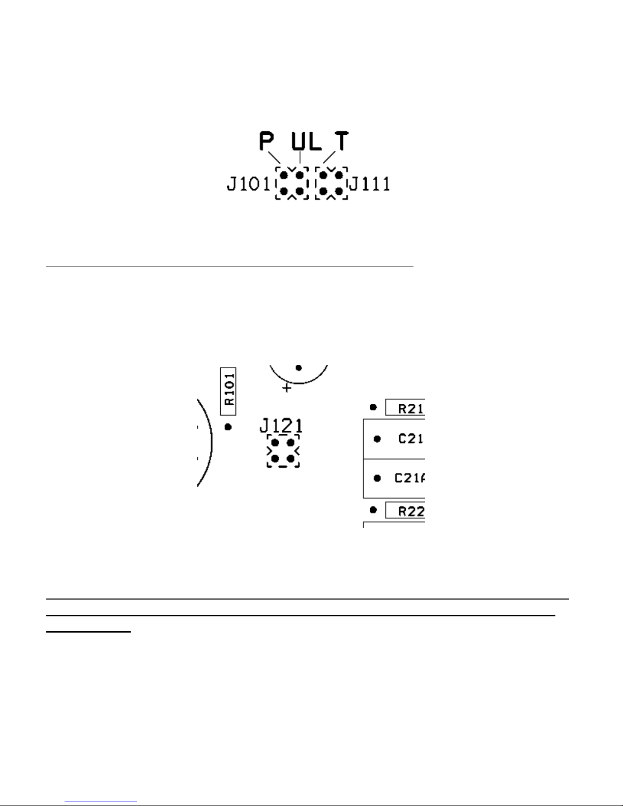
CONFIGURATION JUMPERS – MODE OF OPERATION:
The Model 1 has four groups of jumpers intended for setting a mode of operation – Pentode mode
(P), Ultralinear mode (UL) and Triode mode (T). Ultralinear mode can only be used with output
transformer that have additional terminal for UL operation.
Shorting blocks are inserted vertically so that the desired mode of operation is selected. The pair
of pins on the far right side is not used.
NOTE: At any time one of the P, UL or T connections must be used.
CONFIGURATION JUMPERS – GRID BYPASS CAPACITOR:
Jumper J121 (122, 151 and 152) can be used to bypass G2 on the pentode section. The bypass
is preferred by some designers, it will result in slightly different sound and we decided to have it
included as an option.
In order to engage the bypass, the shorting block should be inserted horizontally shorting two
lower pins. The upper pair of pins is not connected anywhere and can be used to hold shorting
block if the bypass is not desired.
NOTE: The grid bypass should only be used with Pentode mode of operation.
Using it in any other mode will cause damage to the amplifier and/or output
transformer!
11
Page 12
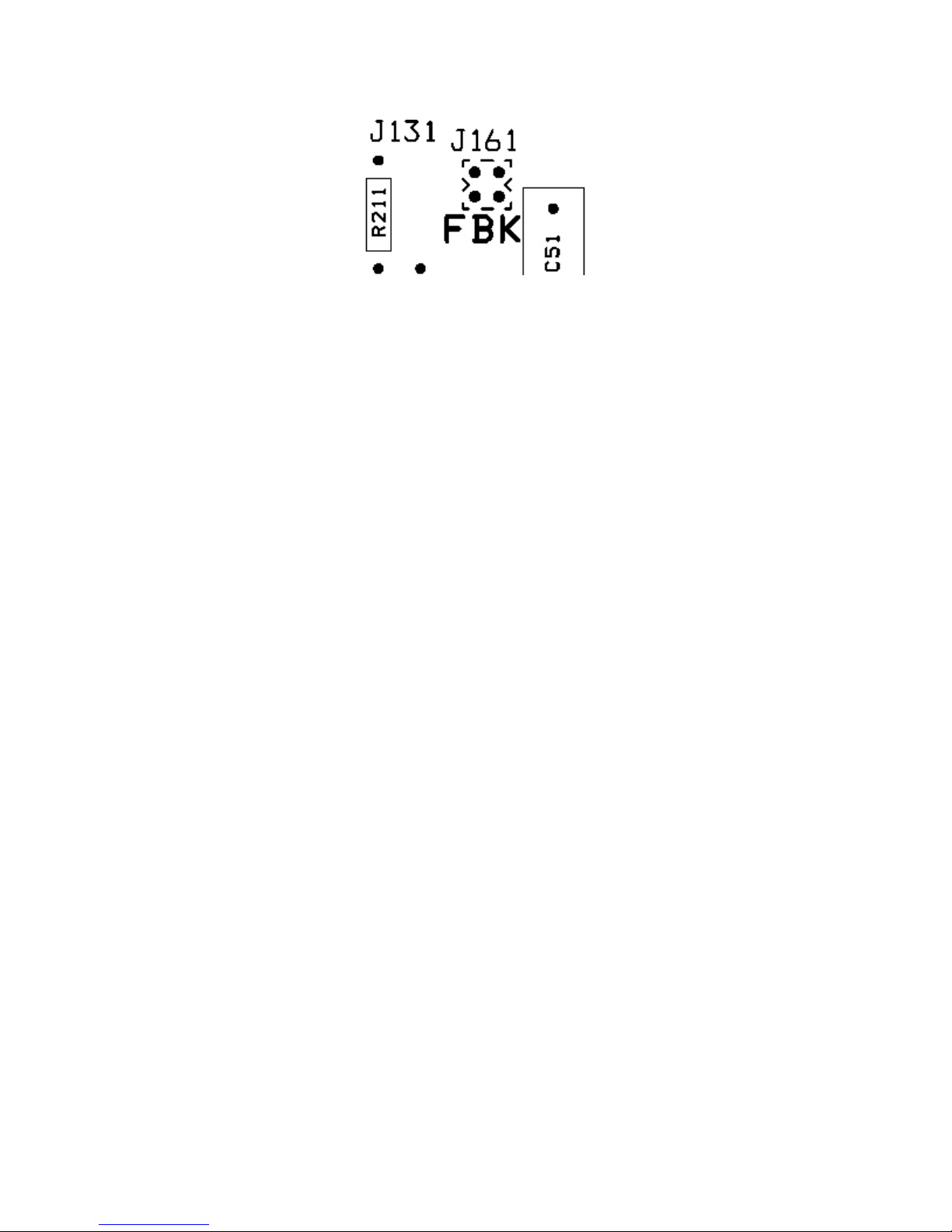
CONFIGURATION JUMPERS – NEGATIVE FEEDBACK SELECTION:
The Model 1 has optional negative feedback connection provided by jumper J161 (J162) – FBK.
By moving the shorting block horizontally across the two lower pins, the negative feedback will be
engaged. The upper two pins are shorting block holders when feedback is not engaged. By using
negative feedback you will reduce the amplifier’s gain, increase bandwidth and reduce distortion.
All the good stuff, but harmonic content will change, and many people do not have much respect
for that kind of sound. Again, option is available, and you need to find an answer for yourself. The
amount of feedback applied can be modified by changing value of R181 and R182. You will notice
variations in the sound, but be careful, poorly compensated feedback will cause the amplifier to
oscillate.
CONFIGURATION JUMPERS – TRIODE PARALLEL CONNECTION
Jumpers J171, J172 are used in the Full pack configuration to parallel cathodes of the input
triodes when the bypass capacitors (C61, C62) are used. If you do not need an extra gain this
capacitor provides, you can safely take it out, and then disengage J171/172 too see if you may
prefer the new sound.
HEATER CONFIGURATION JUMPERS:
Ten zero ohm resistors R290-R380 can be used for different heater configurations. The most
commonly used configurations are:
- Two tubes, Basic configuration (V1 and V2), heaters in series (Vf=32V, If=0.3A): use R290,
R370 and R380
- Four tubes – Full pack (V1-V4), V1 and V2 heaters in series, V3 and V4 heaters in series,
the two groups of heaters connected in parallel (Vf=32V, If=0.6A): use R290, R370 and
R380 (V1 and V2) and R310, R340 and R360 for V3 and V4 heaters.
- ECL82 heaters (6.3V) – connect all heaters in parallel, using R290 to R360.
12
Page 13
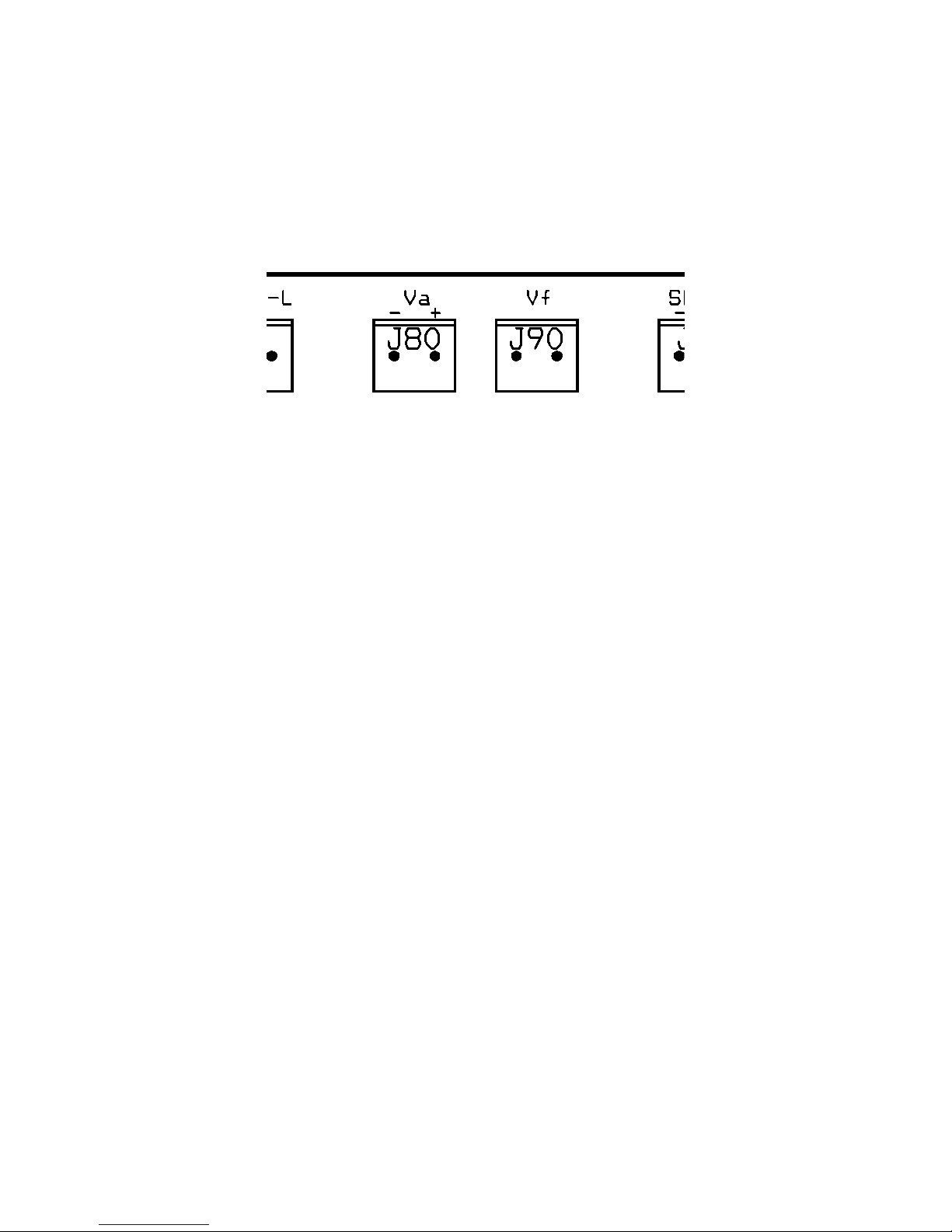
CONNECTING POWER:
As any other vacuum tube amplifier, Model 1 needs two voltages for proper operation: (1) Plate,
or Anode voltage, Va and (2) Heater, or filament voltage Vf. Plate voltage should be brought to the
terminal block J80 and filament voltage to J90. Picture below shows the layout detail with J80 and
J90.
Plate voltage (Va) should have nominal value of 250V (acceptable range is 200-270V). The power
source should be able to provide 80-100mA for basic configuration and 160-200mA for the full
pack. Sound is significantly affected by the power supply quality, so make sure to have sufficient
filtering.
PCL82 tubes are designed for series connection of their filaments, so they require current source
(as opposed to some other tubes that require voltage source for filament supply). Heater
specification for this tube is 0.3Amp and 16V. Rugged construction of the tube’s heater allows that
it is powered from the voltage source as well, but you can expect high current surge and bright
yellow heater in the first few seconds of operation. In theory, this reduces life of the heater, but
these tubes are very rugged and will have long life even in this less than perfect situation. Basic
version of the Model 1 amplifier has the two heaters connected in series, so the filament supply
needs to be able to provide 32V at 0.3A. Resistors R290-380 are placeholders for jumpers which
allow for different heater configurations. ECL82 tubes (which are PCL82 equivalents with 6V
heaters) can also be used, by configuring all heaters in parallel (R290 to R360 installed, R370,
380 left out). For more details refer to the description of the heater configuration jumpers, above.
Filament voltage can be DC or AC, so there are no polarity markings on J90. If the DC is used, left
pin is the system ground (see the Figure above), so the negative polarity of the filament voltage
can be connected to that pin, although doing opposite will not affect operation, as long as filament
supply is independent of plate supply.
13
Page 14
CONNECTING OUTPUT TRANSFORMERS:
For basic model, the output transformers should be designed to provide 5kΩ primary resistance.
For the full pack, the primary resistance should have 2.5kΩ rating. Rating of the secondary
winding should correspond to the impedance of your speakers (4, 8 or 16Ω, typically). There are
many transformers in the market that have multiple taps to accommodate various combinations.
Power rating should be minimum 3W for basic and 6W for full-pack configuration.
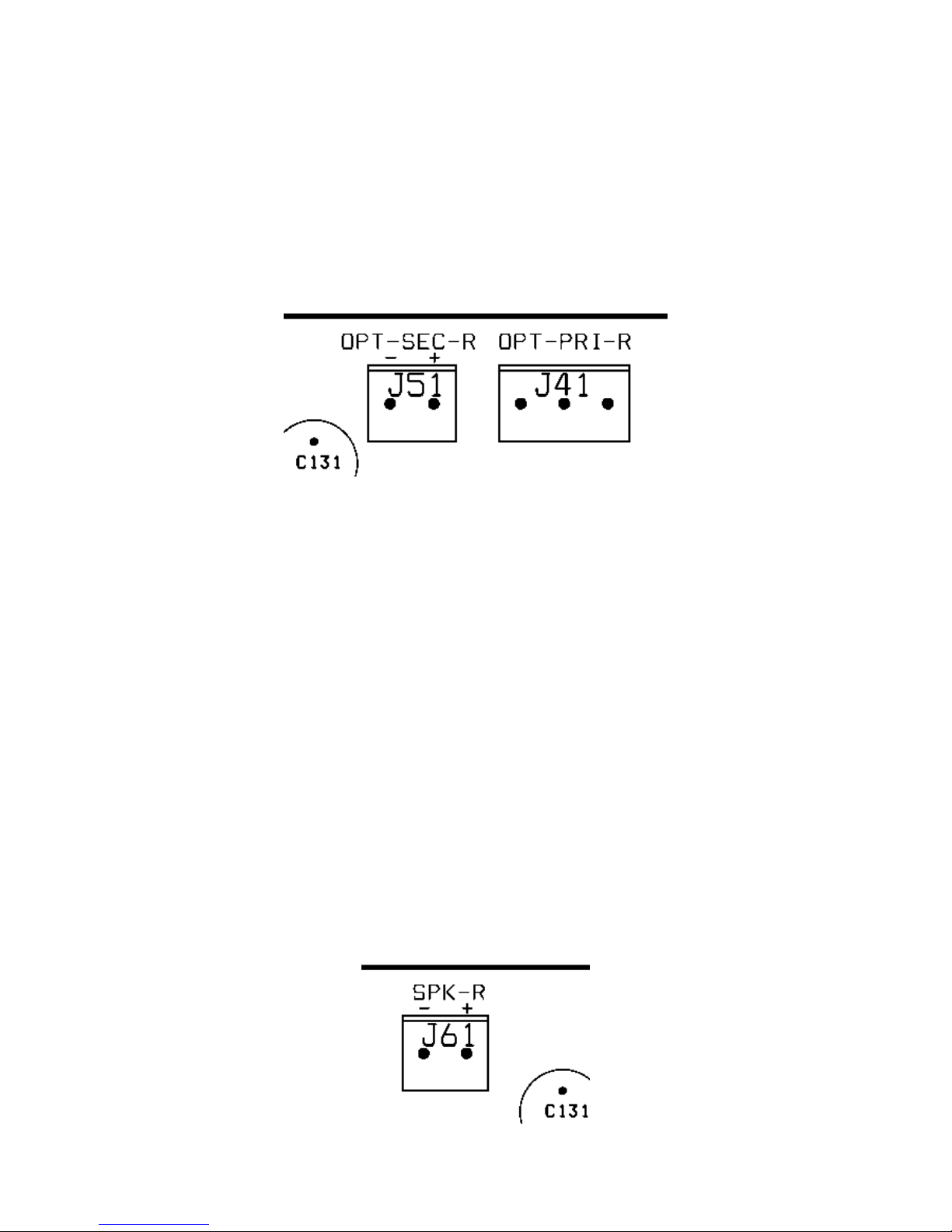
Model 1 features two pairs of terminals for connecting output transformers. The terminals are J41
and J51 for the right channel transformer and J42, J52 for the left channel. The terminal blocks for
the right channel connections are shown below.
.
Output transformer’s primary winding is connected to the two end terminals of J41. Right side
terminal of the J41, as shown on the picture above, is connected to +Va, and the left end is
connected to the plate of the pentode part of PCL82. Middle terminal is used for the ultralinear
connection if the transformer has the UL tap.
Left channel transformer is connected the same way using J42.
Transformer’s secondary winding is connected to J51 (J52 for the left channel). Terminal with
minus sign is connected to the system ground.
It is important that both, left and right output transformers are connected identically, which will
ensure that both channels operate in phase and provide adequate stereo picture.
If the negative feedback is to be used, it is also important that the primary and secondary are
connected in phase, so please carefully check transformer documentation. An oscilloscope is
valuable tool if you use old, second hand transformers which may not have adequate markings.
CONNECTING SPEAKERS:
Speakers’ impedance should match rated secondary impedance of the output transformer.
Speakers are connected to terminals J61 (right speaker) and J62 (left speaker).
14
Page 15

Again, for best stereo image, they should be connected in phase. The second harmonic
distortion is common with single ended amplifiers (it gives them specific, rich sound), and air
transports sound with some degree of the second harmonic distortion too. It is possible to notice
change in sound and reduction in distortion just by swapping plus and minus terminals, and we
encourage you to experiment and find what sounds best for you. If you are swapping terminals,
make sure to do it on both speakers at the same time, to preserve stereo image.
CONNECTING HEADPHONES:
Headphone output is not a typical feature of a tube amplifier. There are technical and commercial
reasons (it increases manufacturer’s cost). We wanted to make sure that Model 1 can be used as
a headphone amplifier too, so the output is there. We were able to take advantage of the
amplifier’s relatively low output power and came up with a clever way to have the amplifier work at
normal power levels with headphones (Watts instead of milli Watts) and even to push the amplifier
to clipping, if needed.
Connecting headphones is fairly straightforward: use standard 3.5mm headphone connector J8
and flip the switch SW1. SW1 will engage dummy load across the output transformers and bring
signal to the headphones. We believe that this is the best way to preserve the original sound of
the amplifier when headphones are used. With headphones (which are typically very low power
devices) the amplifier will operate properly loaded up to maximum output, and you can even enjoy
the specific sound of tubes’ soft clipping, if you desire (this may be very interesting if you intend to
use the Model 1 as a guitar amplifier and not disturb anybody).
Dynamic headphones come in several nominal impedances – 16 to 600 Ω and you may notice
that the maximum sound level is too high or too low. You can adapt the Model 1 amplifier to your
headphones by changing resistors R281 and R282. The resistors are in series with the
headphones, and by increasing their value you will increase attenuation.
VOLUME CONTROL AND AUDIO INPUTS:
Less expensive stereo potentiometers have poor symmetry between the two parts and we did not
want to burden the product with expensive ones, so we went with separate volume controls for the
left and right channel.
One pair of analog inputs is installed as a standard feature and there is a place for another pair of
inputs, if you need to connect more than one source. The input selector is not required, since the
source that is not used will not affect the active one. If you have both sources working at the same
time, you will hear a strange mix of the two inputs.
The gain of the amplifier will change, depending on whether or not you decide to use the negative
feedback . Gain is significantly higher without feedback, so you will not need to turn the volume
knob that far to get to clipping. With the feedback engaged (you can do it by moving jumpers on
J161, J162 one position down) the gain will drop significantly, and the volume knob will have to
travel further for the same output power.
15
Page 16

UPSIDE - DOWN ASSEMBLY
The Model 1 printed circuit board (PCB) was designed with top to bottom symmetry. This
symmetry enables building a tube amplifier with “tube audio look”, where tubes are mounted on
top of the chassis. All parts, except tube sockets, can be mounted on the bottom of the board and
soldered on the top side (top side is the one with component references in white silkscreen). That
way, the PCB can be mounted close to the top of the chassis and tube sockets can be flush with
the top, or even slightly higher, depending on your preferences. There are few things to keep in
mind though:
- Top of the PCB should be at least ¼” below the chassis, to prevent metal chassis from shorting
PCB circuits.
- PCB has a 1/8” hole underneath the sockets. Make sure to provide support to the PCB using the
holes (in addition to the five mounting holes), to prevent board flexing and possible damage to the
PCB when tubes are inserted or removed.
- You may find it convenient to use chassis mounted sockets, in which case there is no stress on
the PCB during tubes insertion/removal. From the chassis mounted socket you can “drop” wires to
the PCB. Be sure to use short insulated wires.
- If you mount headphones connector to the bottom of the board, left and right channel will swap.
To bring everything back in order, you will need to swap inputs. Then your speakers will have left
and right channel swapped. To rectify that, you will need to connect left speaker to the right
channel and vice versa. Or, you can simply use a chassis mounted headphone jack and connect
wires to the PCB in the right order.
- When the headphones/speakers selector switch is moved to the bottom, it will reverse the
function – headphones position will turn the speakers on and vice versa. We do not think this is a
major issue but you should be aware.
- If you move volume control potentiometers to the bottom of the PCB, the minimum volume
position will become maximum. It may be cool, but it could also be annoying. The only solution to
the problem is to use chassis mounted potentiometers and bring wires to the PCB.
- If you use chassis mounted parts (input jacks, headphone connector, switch and volume control,
make sure to use short coaxial cables to minimize noise pickup and stray capacitances that may
cause amplifier to oscillate.
16
Page 17

FINAL WORDS
Once again, thank you for your purchase. We hope that the Model 1 will give you hours and hours
of fun and have you experience a multitude of different qualities of the “tube sound”. Once you
have exhausted all of the options, we hope that you will “retire” the amplifier from your bench into
a nice chassis and have it rest on your work desk or in the bedroom accompanied by a PC or an
MP3 player of some kind. Once all experiments are finished, make sure to permanently short
selected jumpers (one way is to bend the pins and solder them together) in order to prevent
deterioration of contacts over time. Robust design should provide you with years of pleasant
sounds, with only maintenance being change of tubes, once the original ones are too weak to
rumble. Our design is really gentle with the tubes, so they should last much longer than tubes in
some other designs that try to pull the last milliWatt out of them.
Finally, we want to remind you once again to take extreme caution while working with high
voltages. If you are not thoroughly familiar with the safety procedures, feel free to enlist help of a
relative or friend. There are many very knowledgeable people in this field and they all share
passion for spreading the art and science of high quality sound reproduction.
Copyright, ENG Vista, Inc. 2007
17
Page 18

PARTS LIST
Parts with asterisks in the VALUE column are used in the Full-Pack assembly.
Item Qty
Reference
EPN Value
1 2
2
14
3
8
4 2
5 2
6 2
7 2
8
4
9 2
2
10
11
2
12 2
13 2
14 2
15
6
16 2
17 3
18
7
19 1
20 1
21
8
22
8
R41, R42
R11, R12, R51, R52, R121, R122,
R141, R142, R181, R182, R231, R232,
R241, R242
R21, R22, R61, R62, R201, R202,
R391, R392
R71, R72
R81, R82
R91, R92
R101, R102
R111, R112, R131, R132
R151, R152
R161, R162
R171, R172
R191, R192
R211, R212
R221, R222
R251, R252, R261, R262, R271, R272
R281, R282
R290, R370, R380
R300, R310, R320, R330, R340, R350,
R360
F10
F20
J101, J102, J111, J112, J121, J122,
J161, J162
J131, J132, J141, J142, J151, J152,
J171, J172
N/U
200-0003 1k
200-0003 *1k*
202-0001 *220k/0.5W*
202-0001 220k/0.5W
200-0004 *2k2*
200-0004 2k2
200-0005 100R
200-0007 470k
202-0002 22k/0.5W
202-0002 *22k/0.5W*
206-0001 510R/2W
200-0005 *100R*
206-0001 *510R/2W*
206-0002 27R/2W
204-0002 39R/1W
N/A 0R
N/A *0R*
170-0001 500mA
170-0002 3A
161-0001 JUMPER 2X2
161-0001 *JUMPER 2X2*
6
23
24
6
25 2
26 6
27
6
4
28
29 6
30 2
31
2
2
32
33 4
34 2
35
2
36 1
1
37
38
1
39 1
40 1
2
41
42 1
43
2
44
2
2
45
2
46
47 1
48 1
@J101, J102, J121, J122, J161, J162
@J131, J132, J151, J152, J171, J172
J41, J42
J51, J52, J61, J62, J80, J90
C11, C11a, C12, C12a, C51, C52
C21, C21a, C22, C22a
C41, C42, C81, C82, C131, C132
C61, C62
C71, C72
C101, C102
C91, C92, C111, C112
C121, C122
C141, C142
J8
J11
J12
J21
J22
P11, P12
SW1
@V1, V2
@V3, V4
V1, V2
V3, V4
PCB
User Manual
161-0002 SHORTING BLOCK, 0.1"
161-0002 *SHORTING BLOCK, 0.1"*
160-0003 CONN PCB 3
160-0004 CONN PCB 2
100-0006 100n/250V
100-0006 *100n/250V*
100-0001 10u/350V
100-0002 220u/35V
100-0003 1n/50V
100-0001 *10u/350V*
100-0002 **220u/35V** - NOT USED
100-0004 1n/500V
100-0007 470p/50V
160-0005 PHONEJACK STEREO SW
160-0001 RCA-RED
160-0002 RCA-WHITE
160-0001 *RCA-RED*
160-0002 *RCA-WHITE*
209-0002 50k, audio
180-0001 SW DPDT
990-0002 9-PIN MINI SOCKET
990-0002 *9-PIN MINI SOCKET*
990-0001 PCL82
990-0001 *PCL82*
500-0001 PCB
500-0001 User Manual
18
 Loading...