

Page 1
INSTALLATION
INSTRUCTIONS
TAPWARE
Englefield
STUDIO
If you are building a
bathroom from scratch,
giving your bathroom a
makeover or just replacing
an old tap, Englefield can
provide a solution for you.
ROUGH-IN
NEW ZEALAND
KOHLER NZ LTD
Free Ph: 0800 100 382
Free Fax: 0800 664 488
www.englefield.co.nz
AUSTRALIA
KOHLER CO.
Free Ph: 1 800 ENGLEFIELD
(1 800 364 533)
www.englefield.com
For warranty information, please visit our website
Page 4
1315151-AN2-B July 2017
Englefield
INSTALLATION INSTRUCTIONS
STUDIO Pin Lever Shower or Bath Mixer
BEFORE YOU BEGIN
All information is based on the latest product information available at the time of
publication. ENGLEFIELD reserves the right to make changes in product
characteristics, packaging, or availability at any time without notice.
Please leave this installation guide for the consumer as it contains
important information.
NOTES:
1. Flush the water supply pipes thoroughly to remove debris.
2. Ensure all local plumbing codes are observed.
3. Optimum working pressure: 100kPa to 500kPa.
4. Minimum working pressure: 35kPa.
5. Maximum working pressure: 500kPa.
6. If pressure exceeds 500kPa, a pressure limiting valve must be installed.
7. All installations should comply with the relevant requirements of AS/NZS 3500.
CLEANING INSTRUCTIONS
All Finishes: Clean the finish with mild soap and warm water. Wipe entire surface completely dry with a
clean soft cloth. Many cleaners may contain such chemicals as ammonia, chlorine, toilet chemicals etc. which
could adversely affect the finish and are not recommended for cleaning.
Do not use abrasive cleaners or solvents on Englefield tapware.
CONTACT AND WARRANTY INFORMATION
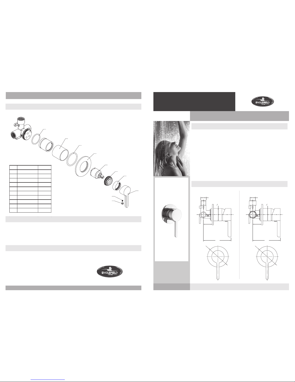
SPARE PARTS LIST
35 - 60
107
Ø80
3 x Male G1/2’’
1315151-AN2-B July 2017
No. Description Part No.
1 Plug
2 Screw
3 Pin lever handle 1315417-* *
4 Bonnet 1250280-**
5 Nut
6 Cartridge
7 Face plate
8 O-ring
9 Outer sleeve
1 0 O-ring
1
2
3
4
5
6
7
8
9
10
35 - 60
107
Ø80
3 x Female Rc1/2’’
1250284
1250283-**
1250282
1250278
1315418-**
1315419
1315420-**
1315422
** Please specify a colour when ordering:
-CP (Chrome),
-BN (Brushed nickel),
-BL (Matte Black)
97533A-4 97533A-N4 (Female Rc1/2” connections)(Male G1/2” connections)
97533A-4
97533A-N4
Pin Lever Shower or
Bath Mixer
97533A-N4 Female Rc1/2” valve (Shown)
97533A-4 Male G1/2” valve (Not Shown)
O48 O48
Page 2
INSTALLATION - FINISHED WALL
INSTALLATION - IN-WALL VALVE
1315151-AN2-B July 2017
Page 2
Englefield
1315151-AN2-B July 2017
Page 3
Englefield
STUDIO Pin Lever Shower or Bath Mixer
INSTALLATION INSTRUCTIONS STUDIO Pin Lever Shower or Bath Mixer INSTALLATION INSTRUCTIONS
NOTE: DO NOT DISCARD THE PLASTIC GUARD UNTIL THE FINISHED WALL HAS BEEN COMPLETED.
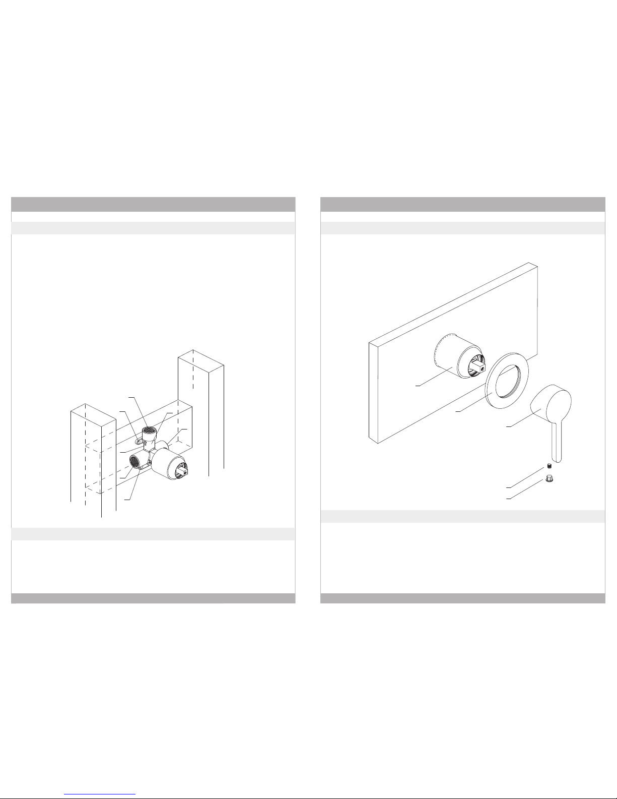
1.) Determine where the in-wall valve(1) will be located in the wall.
2.) Construct a suitable nog for mounting the in-wall valve. Ensure the nog is level and at the correct depth.
Note: Distance of the inlet centres from finished wall: 35-60mm.
3.) Ensure the arrow mark(2) on the valve body is pointing up. The hot water inlet(3) is on the left. Fix the
in-wall valve body onto the nog through at least two of the lugs(4). Note: Fixing screws not supplied.
4.) There are two valve connection types available: Male G1/2” and Female Rc1/2”.
Make sure you have the correct version for your setup and connect the water supply pipes to the
inlets(3)(5)*. Note: Hot inlet(3) is on the left, cold inlet(5) is on the right.
5.) Connect pipes from outlet(6)* to shower head or bath spout, as required.
1.) Ensure that all connections are watertight. Remove plastic guard and ensure the cartridge is in the off position.
2.) Turn on the main water supply and check for leaks. Repair as needed.
3.) Replace plastic guard and ensure the main water supply is turned off.
INSTALLATION CHECKOUT
1.) Remove the plastic guard after the finished wall has been completed
2.) Apply a bead of silicone to the rear of the faceplate(8). Slide the faceplate onto the valve body(7). Push it
firmly against the wall.
3.) Install the pin lever(9) on the cartridge and tighten the grub screw(10) with the hex key.
4.) Insert the plug(11) into the handle.
INSTALLATION - TRIM KIT
1.) Install the finished wall up to the plastic guard. Note that the faceplate diameter is 80mm and ensure
an adequate sealing surface is provided.
7
8
9
10
11
1
4
6
2
3
5
4
* Female Rc1/2” valve (Shown)
Male G1/2” valve (Not shown)
 Loading...