

Engineering Solutions OMNIGUARD 4 Owner's Manual

Owner's Manual
TM
OMNIGUARD 4
DIFFERENTIAL PRESSURE RECORDER
Advanced Test Equipment Rentals
www.atecorp.com 800-404-ATEC (2832)
®
E
s
t
a
b
l
i
s
h
e
d
1
9
8
1

Serial #:
Dealer Name and Address:
Date of Purchase:
Name
Address
City, State, Zip
Phone
Registered to:
Name
Address
City, State, Zip
Phone
The serial number is located inside the case lid.
6000 Southcenter Blvd, Suite 70
Seattle, Washington 98188-2439
(206) 241-9395 • (206) 241-9411 fax
www.engsolinc.com
OMNIGUARD 4
Differential Pressure Recorder
Advanced Test Equipment Rentals
www.atecorp.com 800-404-ATEC (2832)

SOLUTIONS
Page 1
Owner’s Manual
P/N OG4-MAN.100
Contents
Introduction ................................................................................. 2
Section 1: Basic Care ................................................................... 4
Section 2: Navigating The LCD Display ........................................ 5
Section 3: Quick Setup & Usage ..................................................6
Sample Session: Viewing/Changing Settings ..................
6
Hanging the Omniguard 4 ..................................................... 7
Display Modes ...................................................................... 7
Loading the Thermal Printer Paper ....................................... 8
Section 4: Detailed Operation ...................................................... 9
Work Area Setup ................................................................... 9
Power-Up ............................................................................. 9
Contractor Name .................................................................. 10
Date & Time .......................................................................... 10
Alarm Setpoint Selection ...................................................... 11
Example of Setting Alarm Levels ....................................
11
Starting/Ending A Job ...........................................................12
Alarm Condition ....................................................................13
Alarm Silence, Disable and Rearming ................................... 13
Turning Printer On/Off .......................................................... 14
Viewing/Printing Jobs & the Print Job Key ........................... 14
Configuration Report ............................................................ 15
Example of Typical Job Printout .....................................
15
Example of Job Summary Printout .................................
15
Description of Controls .........................................................16
Print/Log Rates ..................................................................... 18
Inlet Pressure Response Rate ............................................... 18
Display Contrast & Backlight ................................................19
Pressure Units ...................................................................... 19
Passcode Protect ..................................................................20
Aux Alarm Setup ...................................................................20
Zero Calibration ....................................................................21
Using Help ............................................................................ 22
Communication .................................................................... 22
Transferring a Job Log to the PC ....................................
22
Remote Monitoring & Modem Setup .................................... 23
Communication Remote Monitoring Screen ...................
24
Appendix A: Troubleshooting ...................................................... 25
Shipping & Repair ..........................................................
26
Appendix B: Specifications .......................................................... 27
Appendix C: General Guidelines to Establishing
a Containment Site ........................................... 28
Appendix D: Limited Warranty ..................................................... 30
Advanced Test Equipment Rentals
www.atecorp.com 800-404-ATEC (2832)

ENGINEERING
Page 2
Omniguard™ 4
Introduction
Unpacking
The
Omniguard 4
is shipped complete and ready to use. When
unpacking the unit, please check for the following items:
• Roll of thermal paper (installed)
• 10 ft. inlet pressure tubing
• Owner’s Manual
• Registration Card
Save the shipping box and packing material, in the event the unit
must be shipped to another location or for service. If you are missing
any items shown on the packing list, or if you have any questions
regarding your
Omniguard 4
, please call your dealer or Engineering
Solutions at (206) 241-9395.
Please remember to fill out and return the Registration Card.
Owner’s Manual Overview
This manual covers the setup and operation of the
Omniguard 4
. It
uses several different fonts and other special characters to make
various unit functions and types of reporting easy to identify. Below
is an example of each:
• Text printed on the display screen is shown as: ALARM 1
• Thermal printer text is shown as: NORMAL OP
• Keys and connectors on the front panel are shown as: ALARM
SILENCE
Features
• Real-time differential monitoring of vacuum and/or pressure
level
• Extremely simple to setup and use, with on screen help available
via a HELP key
• Log and track by Jobs. Stores multiple jobs, each with unique job
name and starting/ending dates
• Contractor name appears in all Job Logs
• Programmable high and low alarm settings
• Windowed case lid allows viewing pressure reading and status
from across the room, operates with lid closed to prevent
damage to unit from water and other construction debris
• Large easy-to-read graphic LCD display with backlight shows
current pressure reading, operation status and alarm setpoints
Omniguard ™ 4
Differential Pressure Recorder
Advanced Test Equipment Rentals
www.atecorp.com 800-404-ATEC (2832)

SOLUTIONS
Page 3
Owner’s Manual
• Multiple display modes, allows easy viewing of pressure reading
from a distance, modes toggled by DISPLAY key
• 30+ days internal memory stores pressure readings and alarm
occurrences with a date/time-stamp, complete record of operation
available for printing and transfer to computer
• Built-in hanging clip gets unit off the ground and away from
possible damage, allows easy viewing of monitoring status
• Totally self-contained unit, all necessary parts store securely
inside the lid
• Temperature compensation circuitry eliminates the need for off-
site calibration
• Pressure readings displayed in Inches WC, Millimeters WC or
Pascals
• USB and Serial ports support PC communication for transferring
job logs to a computer
• Audible and visual alarm systems with Alarm Silence function
• Operating temperature range 30°- 130°F
• 1 Year Warranty
Accessories
• Remote high intensity strobe light with 95db alarm & 25 ft. cable
• Telephone autodialer for off-site alarm notification
• External modem supports remote off-site monitoring and log
tranfers to office computer
• Battery pack for portable operation
• NIST traceable certification
• 220VAC, 50Hz power supply operation
• Alternate operating pressure ranges
Advanced Test Equipment Rentals
www.atecorp.com 800-404-ATEC (2832)

ENGINEERING
Page 4
Omniguard™ 4
Section 1: Basic Care
The
Omniguard 4
is built and engineered to provide you with
dependable performance for years to come. Following these basic
guidelines will insure that you get maximum use from your unit.
Once the unit is set up, field operation is easy. Complete reports are
virtually automatic, providing the most accurate records of your job
site conditions available.
• This unit is designed to measure differential pressure only from
+0.250” to -0.250” WC (optional pressure ranges are available).
Caution: Never apply pressure to the inlet port by
mouth or with any other strong pressure device.
High pressure will permanently damage the
sensor.
• Use only
Omniguard
thermal printer paper.
• Always store the unit away from sources of excessive heat, dust
and moisture.
• Never attempt to repair any of the internal components of the
unit.
• Protect the unit from strong shocks or vibrations. Be sure the lid
is securely closed whenever transporting the unit.
• Be sure to plug your
Omniguard 4
into a power supply that
complies with the National Electrical Code. Keep all connections
dry. As with any electrical device, this unit has the potential to
cause an electrical shock hazard.
• If your unit must be shipped at any time to another location or for
service, use the original packing material and shipping box for
optimum protection during shipping.
Advanced Test Equipment Rentals
www.atecorp.com 800-404-ATEC (2832)

SOLUTIONS
Page 5
Owner’s Manual
ALARM SETPOINTS
-Alarm 1 is upper setpoint.
Alarm 2 is lower setpoint.
-Normal operating window
is area between Alarm 1
EXI T HE LP
HELP INFO
Alarms 1 & 2 are upper
and lower setpoint.
Defaults are -0.025 and...
-0 .0 25
ALARM 1:
ALARM 2: -0.100
S ELE CT S AVE EXIT HELP
0
-0.20
VI EW/PRINT JOB LOGS
PRINT JOB KEY SETUP
CONFIGURATION REPORT
PASSCODE PROTECTION
CONTRACTOR NAME
S ELE CT EXIT H ELP MAIN MENU
"WC
Alarm 1: -0.025"
Alarm 2: -0.100"
N O R M A L
-0.058
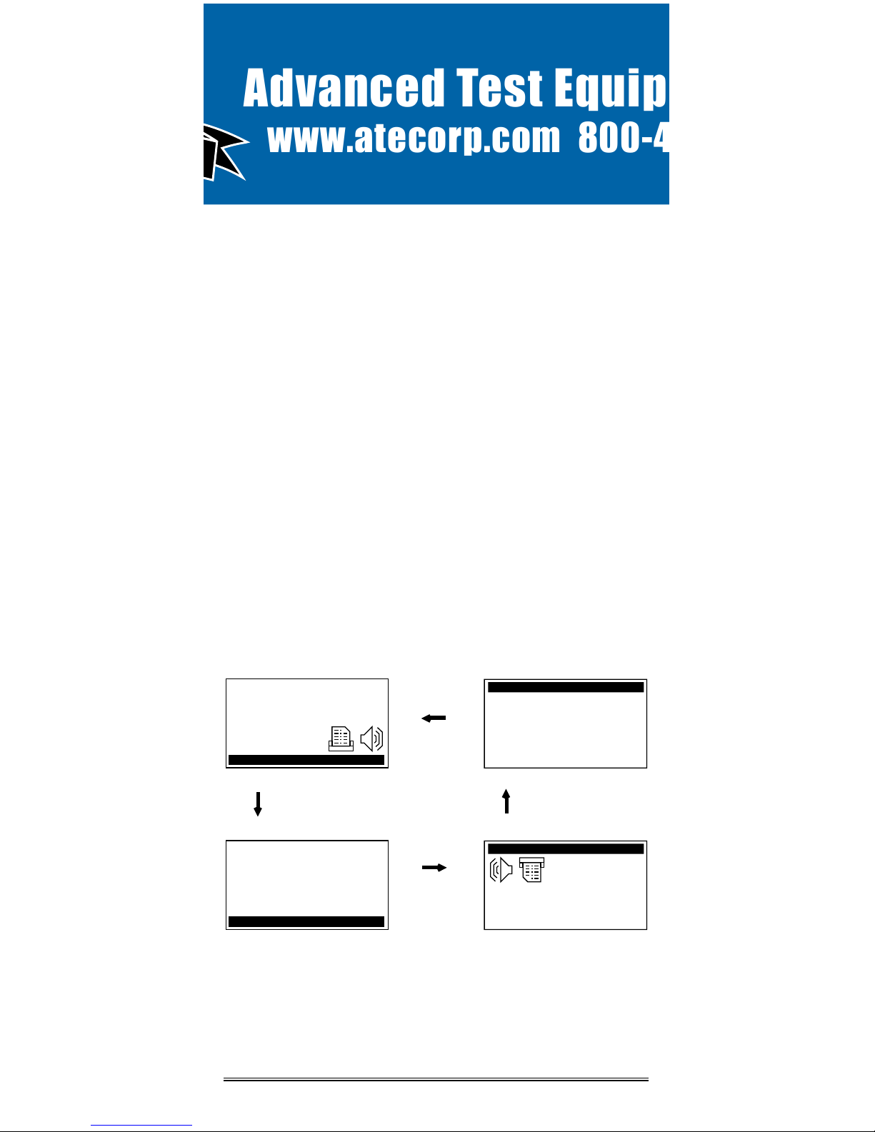
Section 2: Navigating The LCD Display
The
Omniguard 4
display features four screen types, shown below.
Press the indicated key to move from screen to screen.
Monitor Screen
Pressure in “WC
Alarm 1 & 2
Setpoints
Printer On
Buzzer Armed
Status Bar
NORMAL
View Settings Screen (
Alarm Setpoints shown)
Setting being
changed (edited)
Valid Key
Choices
Function
Name(s)
Operating Window
use ▲ / ▼ to
change value of
setting
Info Box
NORMAL
Help Info Screen (
Alarm Setpoints help shown)
Valid Key
Choices
Function
Name
Detailed
Help Info
Screen Name
end of menu
indicator
indicates more
help info available
press
HELP
press
SELECT
press
MENU
Main Menu (
Help Menu uses same format)
Highlighted Item
Valid Key
Choices
Menu Items
Screen Name
end of menu
indicator
indicates more
items available
press
HELP again to go to Help Menu Screen
press
EXIT to return to previous screen or Monitor Screen
Advanced Test Equipment Rentals
www.atecorp.com 800-404-ATEC (2832)

ENGINEERING
Page 6
Omniguard™ 4
Section 3: Quick Setup & Usage
This section is a quick reference checklist for setting up your
Omniguard 4
.
1. Insert one end of pressure tubing inside the containment area.
Connect the other end of tubing to INLET #1.
2. Locate a convenient place for
Omniguard 4
outside the
containment. Plug power cord into a power outlet.
3. Turn the unit on. If the message Set Time & Date pops up, set
the correct Time & Date. This happens if the internal battery is
has died and the built-in clock lost its settings (don’t worry, the
battery is rechargable and lasts over 30 days between charges).
4. Press PRINT JOB for a printout of the previous job, if required.
A report for the previous job can be printed at any time.
5. Press START JOB to begin a new job. Enter a name for the new
job and then press SAVE to save the job name. The previous job
will end and a summary of it will print.
6. Check Alarm 1 & 2 setpoints (displayed in the monitor screen
window), adjust if needed.
7. Zero calibrating the unit before a new job is not required (nor
recommended). If desired, calibrate unit using ZERO
CALIBRATE menu item.
The status bar will indicate WAITING FOR PRESSURE and the
STATUS LED will flash green until containment pressure reaches the
operating window. Once this is reached, the status bar will display
NORMAL and the STATUS LED will change to steady green indicating
that the unit is now in its normal operational mode. Printing and
logging of pressure readings begins once the normal operational
mode is achieved.
During normal operation, the highest and lowest pressure readings
will be printed and logged into memory with a time/date stamp every
15 minutes (the default Print/Log rate).
If the monitored pressure then goes outside the operating window,
the unit will go into alarm mode. The buzzer will sound, the status
bar will change to a flashing >>ALARM<< and the STATUS LED will
flash red. The print and log rate of the pressure readings will
increase to every 15 seconds (the default Print/Log Alarm rate).
Sample Session: Viewing/Changing Settings
1. From the Monitor Screen, press MENU to go to the Main Menu.
2. Use the ▲/▼ arrow keys to highlight ALARM SETPOINTS.
3. Press SELECT to go to the View Setting Screen and allow
changes to the ALARM SETPOINTS.
4. The ALARM 1 setting can now be increased or decreased by
using ▲/▼.
Advanced Test Equipment Rentals
www.atecorp.com 800-404-ATEC (2832)
SOLUTIONS
Page 7
Owner’s Manual
5. Once the desired value has been reached, press
/
to
highlight ALARM 2 setting.
6. Use ▲/▼ to adjust the value of the ALARM 2 setting.
7. Save the updated settings for both Alarm 1 & 2 by pressing
SAVE. Saved settings are printed and logged into memory.
or
EXIT to return to Main Menu without saving.
Note: Press
HELP
at any time to view more
detailed help information.
Hanging the Omniguard 4
The
Omniguard 4
can be hung on a wall for easy viewing and to keep
it off of the floor, away from possible damage. Hanging the
Omniguard
4
by the clip allows the cover to close, protecting the unit from water
damage while allowing the LCD display and STATUS LED to be
viewed through the window on the cover. The hose and AC cord
should exit the case thru the foam slot, then the cover should be
latched closed to protect the unit from water damage.
Use the DISPLAY key to flip the display orientation when hanging the
unit by its handle (see below).
Display Modes
The DISPLAY key on the
Omniguard 4
is used to vary the display
view and orientation to accomodate hanging the unit by its handle.
The pressure reading can be enlarged to enhance viewing from
across the room.
Press DISPLAY to toggle the views in the sequence shown below.
press
DISPLAY
N ORMA L
058
-
.
N ORMA L
058
-
.
"WC
Alarm 1: -0.025"
Alarm 2: -0.100"
N ORMA L
-0.058
"WC
Alarm 1: -0.025"
Alarm 2: -0.100"
N ORMA L
-0.058
press
DISPLAY
press
DISPLAY
press
DISPLAY
Advanced Test Equipment Rentals
www.atecorp.com 800-404-ATEC (2832)

ENGINEERING
Page 8
Omniguard™ 4
Loading the Thermal Printer Paper
Caution: Only use Omniguard thermal printer
paper! Thermal paper prints on only one side, the
side away from the paper roll. If the roll is
installed incorrectly the printer will be able to
advance the paper but be unable to print on it.
C
B
A
B
C
A
1. Cut the end of the paper to a
tapered point.
2. Place the paper A into the tray
so the paper unrolls from the
bottom.
3. Insert tapered point into slot
marked B, feed through until
tapered point can be pulled from
the top at C.
Do not use the
PAPER FEED
key to
advance the paper.
4. From C, gently pull until the
tapered portion is completely
exposed.
5. Replace lid onto the paper
housing and secure with the
thumbscrew.
Advanced Test Equipment Rentals
www.atecorp.com 800-404-ATEC (2832)

SOLUTIONS
Page 9
Owner’s Manual
Section 4: Detailed Operation
The
Omniguard 4
monitors and records the differential pressure
between the #1 inlet port and the #2 (Reference) inlet port.
In abatement applications the
Omniguard 4
should be located
outside the containment area and not in any antechambers (i.e.
shower or changing room). This allows a supervisor or hygienist to
monitor pressure readings without entering the containment area.
Work Area Setup
The
Omniguard 4
should be placed on a solid (non-vibrating)
surface, excessive vibrations disrupt accurate pressure
measurement, hanging the unit on a wall is okay.
1. The intake end of the pressure tubing must be located a minimum
of 5 feet away from any openings or HEPA fan/filter units.
Choose a location away from excessive dust or moisture.
2. Cut a 1/2” slit in the polyethylene barrier and feed approximately
1 ft. of pressure tubing through it. Tape the tubing securely to the
polyethylene.
3. Connect the free end of the tubing securely over the #1 inlet port.
Be careful not to turn the nozzle.
4. The maximum hose length is limited to 70 ft (for 3/16”ID hose).
Lengths beyond 70 ft can degrade reading accuracy.
5. The Alarm 1 and Alarm 2 settings should be in negative units
when used to monitor a negative containment area. For positive
containment applications, use positive units (Inches WC,
Millimeters WC or Pascals) for alarm setpoints.
NOTE: It is important that there be no kinks or
sharp bends in any part of the tubing. Any blockage
could inhibit accurate recording of the pressure
in the containment area.
Power-Up
To begin operating the
Omniguard 4
, plug the power cord into a
standard wall outlet supplying 115VAC, 60Hz and press the POWER
ON/OFF key. The first time a new unit is turned on the settings will
be at default values.
Initial Power-Up
-- the user is asked to set the unit’s Date & Time
and Alarm 1 & 2 setpoints because they are at the factory
defaults.
This happens only until these settings are updated,
usually only the first time the unit is used.
Normal Power-Up Sequence
-- If the unit was properly turned off
after the previous usage, POWER OFF will print. Otherwise
POWER FAIL will print, indicating that an AC power failure
may have occurred. Either message will be followed by the
date and time the unit was last powered off.
Advanced Test Equipment Rentals
www.atecorp.com 800-404-ATEC (2832)
 Loading...