

Page 1
202-123-0001 1PM1000II Pilot Guide & User Manual
9800 Martel Road
Lenoir City, TN 37772
www.ps-engineering.com
PM1000
PM1000
PM1000
II
II
II
4-Place, Panel-Mounted Intercom
Pilot’s Guide
Pilot’s Guide
Pilot’s Guide
Part Number 11920 (with Crew) and 11922 (without Crew)
FAA-Approved TSO C50c
May 2015
May 2015
202
202--
123
123--
0001
0001
Revision 2
Revision 2
Flying Never Sounded So Good! ™
Page 2

2 202-123-0001 PM1000II-Pilot Guide & User Manual
Section I General Information
1.1 Introduction
The PM1000II, is an FAA-TSO approved, panel mounted, 4-place intercom system (ICS). Please read this manual completely to become familiar
with all the features.
This manual contains operational instructions for the following PS Engineering units:
Model Description Part Number
PM1000II 4-place intercom system w/Pilot ISO 11922
PM1000II Same as above w/internal crew 11920
1.2 Description
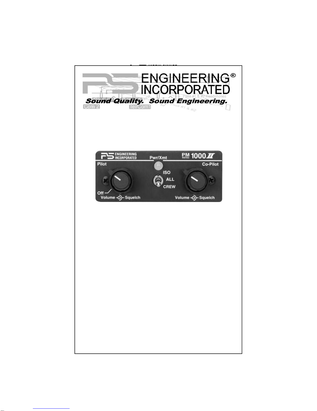
The PM1000II is a 4-place, panel-mounted intercom with individual volume and squelch controls for the pilot and copilot.
Both pilot and copilot have transmit capabilities over the radio. The
PM1000II allows only the person who presses their PTT to be heard over
the aircraft radio. If both pilot and copilot press the PTT at the same time,
the copilot will override (Ideally suited for training environments). Pilot
regains priority by switching the unit off.
1.3 Approval Basis
The PM1000II, part numbers 11920 and 11922 are FAA-approved under
TSO-C50c.
1.4 Specifications
Input power: 13.8 - 27.5 Volts DC
Current Drain: < 250 mA (1 Amp Circuit breaker)
Headphone Impedance: 150-1000 ohms typical
Audio Distortion: <10% @ 75 mW into 150 load
Aircraft Radio Impedance: 1000 typical
3 dB Mic Frequency Response: 350 Hz — 6000 Hz
3 dB Music Frequency Response: 200 Hz to 15 kHz
Unit weight: 12 Ounces (0.342 kg)
Dimensions: 1.25" H x 2.60" W x 5.50" D
(3.2 x 6.6 x 14 cm)
Environmental and technical qualifications: RTCA DO-160B/DO-170
Temperature -20ºC to +55ºC
Altitude 50,000 ft.
Page 3
202-123-0001 3PM1000II Pilot Guide & User Manual
Section II OPERATION
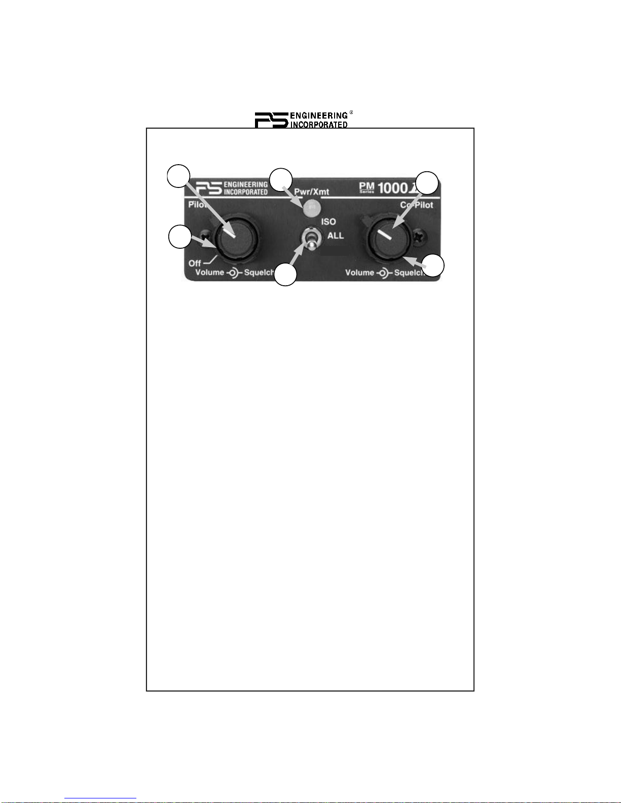
PM1000II with ISO/ALL (p/n 11922)
1 Pilot Volume Control
2 Pilot Squelch Control
3 Copilot Volume Control
4 Copilot Squelch Control
5 Intercom Mode Switch
6 Power/Transmit indicator
Turn the PM1000II on by rotating pilot's volume control (1). This also engages the automatic fail-safe system. The pilot's volume control does not
control the volume of the aircraft radio, allowing an additional degree of
aircraft radio listening flexibility.
2.1 Adjusting The Volume (1, 3)
The pilot's volume control knob (1) adjusts the loudness of the intercom
and music for the pilot only. It has no effect on aircraft radio volume level.
The copilot's volume control (3) adjusts the volume for the copilot.
In the 11920 (PM1000II with Crew) units, the volume level for both passengers can be adjusted by a screwdriver adjusted potentiometer located on
the left hand side of the intercom as viewed from the front. It is possible to
adjust the overall output power to the passenger headsets by changing this
potentiometer. Rotating the potentiometer counterclockwise increases the
passenger volume.
2.2 Squelch Control (2, 4)
The PM1000II provides individual VOX circuits for the pilot and copilot.
The ability to adjust the trip level of these VOX circuits (squelch control)
allows the use of dissimilar headsets without the frustration of clipping the
1
2
3
4
5
6
Page 4

4 202-123-0001 PM1000II-Pilot Guide & User Manual
first syllables. The PM1000II has three squelch circuits, one for the pilot,
copilot, and one for the passengers. With individual VOX circuits, background noise is dramatically reduced.
With the engine running, set the squelch control by slowly rotating the
knob(s) (2) and (4) clockwise until you no longer hear the background
noise in the earphones. When the microphone is positioned properly near
the lips, normal speech levels should open the channel. When you have
stopped talking, there is a delay of about one second before the channel
closes. This prevents squelch closure between words, and helps eliminates
choppy intercom conversations.
2.3 Mode Selector (5)
The center switch (5) is a three position mode control that allows the pilot
to tailor the intercom function to suit flight conditions. Regardless of configuration, the pilot will always hear the aircraft radio. NOTE: If there is a
power failure to the PM1000II, or if the power switch is turned off, the
copilot will not hear the aircraft radio. Only the pilot is connected directly
to the aircraft radio.
ISO (Up Position): The pilot is isolated from the intercom and is connected
only to the aircraft radios. He will hear the aircraft radio reception (and
sidetone during radio transmissions). Copilot and passengers will hear
themselves and music but not the aircraft radio traffic.
ALL (Middle position): All parties will hear the aircraft radio, transmit
sidetone from radio, intercom, and music. However, during any ICS or
radio communications, the music volume automatically mutes. The music
volume increases gradually back to the original level after communications
have been completed.
Units without CREW mode (part number 11922) have a bottom switch
position. This is the same as ALL mode.
PM1000II, p/n 11920, Front Panel Controls
1
2
3
4
5
6
Page 5

202-123-0001 5PM1000II Pilot Guide & User Manual
CREW (Down Position) (ONLY version with crew, part number 11920):
Pilot and copilot are connected on one intercom channel, can hear aircraft
radio and transmit sidetone. The passengers are on a separate and independent channel. The pilot and copilot are connected to the aircraft radio and
may listen to Music #1. Passengers can continue to communicate with
themselves without disturbing the pilot and copilot and may listen to Music
#2.
2.3.1 Entertainment Mute Trip Level
The entertainment mute trip level determines what volume the aircraft radio
must be before the music mutes. This is factory adjusted. If your entertainment does not mute, try increasing the volume of the aircraft radios.
2.4 Power/Transmit indicator (6)
When the PM1000II is operating, the lamp in the center will glow green.
When either pilot pushes a radio microphone key (push to talk, or P-T-T),
the indicator will change to blue (or red in units with serial number K16299
and below), signifying radio transmission.
The aircraft radio sidetone will be presented to the intercom, and heard by
the same people as the aircraft radio receiver audio.
Only the pilot pressing a P-T-T will be heard on the radio, other microphones will be inhibited.
2.5 Fail-safe (1)
If any abnormal conditions occur, such as a loss of radio communication,
bypass the PM1000II by placing it in the “fail-safe” mode. When the
PM1000II is turned off, either by the pilot volume control (1) or by pulling
the “intercom” circuit breaker, the unit automatically enters the fail-safe
mode. In this mode the pilot microphone input is connected to the aircraft
radio output, and the aircraft radio phones input is connected to the pilot
headphone output, enabling pilot radio communication. The copilot and
passenger' stations are inoperative.
Page 6

6 202-123-0001 PM1000II-Pilot Guide & User Manual
Section 3
Warranty and Service
3.1 Warranty
In order for the factory warranty to be valid, the installations in a
certified aircraft must be accomplished by an FAA- certified avionics shop and authorized PS Engineering dealer.
PS Engineering, Inc. warrants this product to be free from defect in
material and workmanship for a period of one year from the date of
installation. During this one year warranty period, PS Engineering,
Inc., at its option, will send a replacement unit at our expense if the
unit should be determined to be defective after consultation with a
factory technician. The customer is responsible for return shipment
costs.
This warranty is not transferable. Any implied warranties expire at
the expiration date of this warranty. PS Engineering SHALL NOT
BE LIABLE FOR INCIDENTAL OR CONSEQUENTIAL DAMAGES. This warranty does not cover a defect that has resulted from
improper or unreasonable use or maintenance as determined by us.
This warranty is void if there is any attempt to dissemble this product without factory authorization. This warranty gives you specific
legal rights, and you may also have other rights which may vary
from state to state. Some states do not allow the exclusion of limitation of incidental or consequential damages, so the above limitation
or exclusions may not apply to you.
3.2 Factory Service
The PM1000II is covered by a one-year limited warranty. See warranty information.
The unit is covered by a one-year limited warranty. See warranty
information. Call PS Engineering, Inc. at (865) 988-9800 before you
return the unit. This will allow the service technician to provide any
other suggestions for identifying the problem and recommend possible solutions.
After discussing the problem with the technician and you obtain a
Return Authorization Number, ship product to:
Page 7

202-123-0001 7PM1000II Pilot Guide & User Manual
PS Engineering, Inc.
Attn. Service Department
9800 Martel Road
Lenoir City, TN 37772
(865) 988-9800 FAX (865) 988-6619
www.ps-engineering.com/suport.shtml
If no method of payment is provided, the units will be returned
COD.
PS Engineering will not be responsible for units returned via US
Mail.
Page 8

8 202-123-0001 PM1000II-Pilot Guide & User Manual
PS Engineering, Inc. 2001 ©
Copyright Notice
Copyrighted information in this manual is subject to change without notice. PS Engineering
reserves the right to improve or change the products or contents of this manual, without
notification of any person or agency. The contents of this pilot’s guide may be downloaded,
stored and reprinted for personal use provided that this copyright information is included.
Commercial use is strictly prohibited. For further information contact the Publications Manager
at PS Engineering, Inc., 9800 Martel Road, Lenoir City, TN 37772. Phone (865) 988-9800
 Loading...