

Engineered Products Co. TIGER 400 HID Installation Instructions Manual

INSTALLATION INSTRUCTIONS
TIGER™ 400 HID Temporary Luminaire
Part Number 15702: TIGER 400 HID Temporary Luminaire: 400-Watt Type-0 Metal Halide Lamp, 6-Foot Cord,
Safety Cage and Lamp Guard.
Part Number 15752: Replacement Type-0 400-Watt Metal Halide Lamp: Pulse-Start
CAUTION
• TO BE INSTALLED BY A QUALIFIED ELECTRICIAN
• WARNING: ELECTRICAL SHOCK HAZARD
• MAKE SURE THAT THE POWER IS “OFF” AT THE CIRCUIT BREAKER BEFORE PROCEEDING
• ULTRAVIOLET AND INFRARED RADIATION IS EMITTED FROM METAL HALIDE LAMPS
Risk of
Electric
Shock
NOTE: Complies with the 2007 Energy Independence and Security Act (EISA) and meets the requirements of the 2017 National Electrical Code (NEC): Articles 410.62 (C) (1 and 2),
410.104 (A), 410.122, 410.130 (F) (5) and 590.4 (F).
Engineered Products Companies TIGER 400-Watt Metal Halide Light Fixture (MHLF) complies with the Department of Energy (DOE) February 2014 updated rule for stringent
energy conservation standards for Metal Halide Fixtures (MHLFs) and its February 10, 2017 implementation date.
• POSSIBLE SKIN OR EYE IRRITATION CAN RESULT FROM EXPOSURES EXCEEDING 15 MINUTES
• DO NOT STARE AT EXPOSED LAMP IN OPERATION
• DO NOT REMOVE THE LAMP FROM LUMINAIRE UNTIL IT HAS COOLED
• NEVER HANDLE THE LAMP WHEN IT IS OPERATING
• RECOMMENDED FOR USE IN “HIGH BAY” APPLICATIONS ONLY! ENGINEERED PRODUCTS
COMPANY DEFINES HIGH BAY AS GREATER THAN 30FEET OFF THE FLOOR
Safety Instructions
1. Use the hook to support the luminaire, not the electrical cord!
2. The luminaire is pre-wired at the factory to operate at 120 volts.
3. The luminaire is equipped with a multi-tap ballast for 120V, 208V, 240V and 277V applications. The leads 208V, 240V and 277V are capped off.
4. Never replace the Type-O lamp with the power supply “ON”.
5. All work must be performed by a qualified Electrician.
6. This luminaire must be installed in accordance with the requirements of the 2017 National Electrical Code and must comply with all state and
local electrical codes.
7. Use only Type-O specified replacement lamps.
Connecting the Luminaire to a Power Supply other than 120 Volts
1. Remove the two (2) screws that hold the Access Cover to the luminaire.
Disconnect and remove the factory supplied power cord (see Figure 1).
Cap the unused supply cord hole.
Power Cord
Access Cover
.75” Knockouts
2. Route the incoming power cord (not supplied) through the knockout hole in the
Access Cover using a strain relief bushing or conduit tting (not supplied).
208V, 240V, and
277V Ballast Leads
3. Remove the caps from the required leads and make sure to label the wires,
then match the voltage of the luminaire supply wires as required.
4. Make all wiring connections.
5. Cap o all unused luminaire wires.
6. Re-attach the Access Cover to the enclosure.
7. Hang the luminaire as directed.
Figure 1. Reconfiguring the Power Supply.
Double check all wiring connections. Ensure that the proper luminaire voltage leads have been selected to
match the supply voltage. Improper wiring may damage the ballast and void the warranty.
www.engproducts.com
5401
SMETANA DRIVE | MINNETONKA, MN
P
800.336.1976
| F
800.336.2801
WARNING
55343
Hook Mounting and Cord Connection
1. This luminaire is supplied with a power cord plug prewired at the factory to operate at 120 Volts.
2. Place self-locking hook over securely mounted eye hanger.
CAUTION
Do not plug in the luminaire!
Safety Guard
Set Screws (4)
Flat Portion
of Safety
Guard
3. Proceed to Lamp Safety Guard assembly instructions.
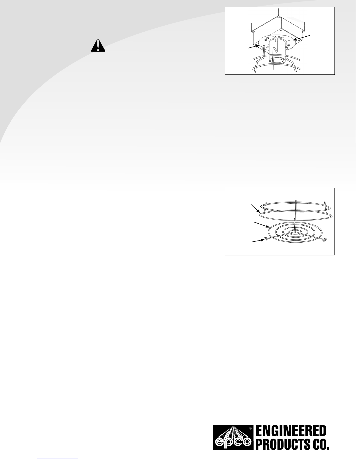
Figure 2. Installing the Lamp Safety Guard.
Safety Guard Installation
1. Place the luminaire on its side with the Access Cover on top. See Figure 2. Locate the four (4) set screws around the upper base of the lamp
socket. Hold the bottom of the Safety Guard (the larger end) and align the top at portion of the Safety Guard over the four set screws and
rotate clockwise. Tighten each set screw until the Safety Guard is rmly attached to the luminaire.
Lamp Installation
1. Install the supplied lamp and make sure that the extended center contact on the bottom of the lamp is fully seated into the luminaire’s lamp
socket to complete the circuit. Note: if the lamp is not fully seated into the luminaire’s lamp socket, the lamp will not light.
Lamp Safety Guard Installation
1. After you have installed the lamp into the luminaire you can now install the Lamp Safety
Guard to protect the lamp from damage.
2. Place the Lamp Safety Guard on a at surface. Locate the three (3) contact points on the
Safety Cage
Lamp Safety Guard, two closed-loop round tangs and one (1) round hook. They should
be facing upward. Connect the round hook onto the bottom section of the Lamp Safety
Lamp Safety
Guard
Guard as shown in Figure 3. The Enshroud should swing downward but still remain
attached to the Lamp Safety Guard by the round hook.
3. Swing the Lamp Safety Guard upward so that one of the round tangs ts onto the
Round
Tangs (2)
bottom section of the Lamp Safety Guard. Then apply upward pressure on the second
tang until it also ts onto the bottom section on the Lamp Safety Guard. Rotate the
Enshroud either left or right to make sure it is rmly attached.
Figure 3. Installing, opening, and closing the Lamp Safety
Guard.
www.engproducts.com
5401
SMETANA DRIVE | MINNETONKA, MN
P
800.336.1976
| F
800.336.2801
Part Number: E02-053-001 (07/17 - AGIII)
55343
 Loading...