

Engineered Comfort 35FH Series, 37FH Series Installation Instructions Manual
INSTALLATION INSTRUCTIONS
HORIZONTAL FAN COIL UNITS
MODEL SERIES: 35FH AND 37FH
Safety Considerations
The equipment covered by this manual is designed for safe and
reliable operation within its design specification limits. To avoid
personal injury or damage to equipment or property while installing
or operating this equipment, it is essential that qualified, experienced
personnel perform these functions using good judgment and safe
practices. See the following cautionary statements.
Danger
ELECTRICAL SHOCK HAZARDS. All power must be disconnected
prior to installation and servicing this equipment. There may be
more than one power source present. Insure that all power sources
have been disconnected to avoid electrocution or shock injuries.
MOVING PARTS HAZARD. Motor and blower must be disconnected
prior to opening access panels. Motors can start automatically;
disconnect all power and control circuits prior to servicing to avoid
serious crushing or dismemberment injuries.
BURN HAZARD. Electrical resistance heating elements must
be disconnected prior to servicing. Electric heaters may start
automatically; disconnect all power and control circuits prior to
servicing to avoid burns.
Caution
The equipment covered by this manual is available with a variety
of options and accessories. Consult the approved unit submittal,
order acknowledgment and other manuals for details on the options
and accessories provided with the equipment on each project. Safe
practices regarding mechanical equipment must be followed at
all times when handling, installing or servicing any unit. All power
must be disconnected before any installation or service should
be attempted. More than one power source may be supplied to
the unit. Power to remote mounted control devices may not be
supplied through the unit. Never wear bulky or loose fitting clothing
when working with mechanical equipment. Gloves should only
be worn when required for proper protection from heat or other
possible injury. Safety glasses or goggles should always be worn
when drilling, cutting or working with chemicals such as lubricants.
Never pressurize any equipment beyond specified test pressures.
The manufacturer assumes no responsibility for personal injury or
property damage resulting from improper or unsafe practices during
handling service or operation of any equipment.
Preface
Nailor Industries fan coils represent an investment, which can, when
installed and operated properly, give long and trouble free service.
Your equipment is initially protected under the manufacturer’s
standard warranty. However, this warranty is provided under the
condition that the steps outlined in this manual for initial inspection,
proper installation, periodic maintenance and everyday operation
of the equipment be followed in detail. This manual should be
fully reviewed in advance of any actual work being done on the
equipment. Should any questions arise, please contact your local
Sales Representative or the factory before proceeding.
Unpacking and Inspection
All units have been carefully inspected, tested and packaged at
Nailor’s manufacturing facility. It is the responsibility of the receiving
party to inspect the equipment upon arrival. Any obvious damage
to the packaging and/or its contents should be recorded on the
bill of lading and a claim should be filed with the freight carrier.
After determining the condition of the unit’s exterior, including all
piping, each unit should be carefully removed from the package
and inspected for hidden damage. Any hidden damage should be
recorded and immediately reported to the carrier and a claim filed.
Should a claim for shipping damage be filed, the unit, the shipping
package and all packing must be retained for inspection by the
freight carrier. All equipment should be stored in the factory shipping
package until installation. At the time of receipt, the equipment type
and arrangement should be verified against the order documents.
Should any discrepancy be found the local sales rep should be
notified immediately so that the proper action may be instituted. The
factory must be notified about any questions concerning warranty
repairs BEFORE any corrective action is taken. Should equipment
require factory operations a Return Authorization Number will be
issued. Any returns not marked with an authorization number will
be refused. The manufacturer will not accept claims for expenses
not authorized.
Receiving Inspection
After unpacking the fan coil unit, check it for shipping damage. If
any shipping damage is found, report it immediately to the delivering
carrier. Store units in a clean, dry location.
CAUTION: Do not use copper coil connections, drain pan
connections, outside air inlet collar, damper shaft, airflow sensor,
electrical conduit, or valve packages as a handle to lift or move
assembly. Damage to the fan coil unit or controls may result.
Ship Loose Items
Items may often be shipped loose for field installation. These items
are shipped loose to offer protection against shipping and job site
damage or by customer request. Refer to packing slip. These items
require the same inspection as the unit.
Minimum Access
Make appropriate accommodations for access panel removal. The
35FH units have access panels on the top, bottom and sides. Some
access may be limited depending on options. The 37FH units have
top and bottom access panels. Electrical enclosures have access
panels that are equipped with hinges. Blowers, motors, coils and
drain pans can be accessed and inspected from the bottom access
panel. For clearances for full opening of hinged access doors, refer
to project specifications, submittal sheets and NEC.
IMPORTANT: These recommendations do not preclude NEC or
local codes that may be in effect, which are the responsibility of the
installing contractor.
For units including valve package enclosures ensure that the access
door to the valve package is not obstructed. Optional universal filter
10/18 EC-35FH-37FH-INST
Engineered Comfort reserves the right to change any information concerning product or specification without notice or obligation.
Dimensions are in inches (mm).
Page 1 of 4
racks if selected provide access for filter replacement from the side
or bottom of the rack. Consult relevant submittals and/or project
plans detailing the location of these items.
Handling & Installation
Even though the Nailor fan coil unit is a sturdily constructed unit,
great care should be taken when handling it. Care should be taken
to protect the blower assembly, coil, piping, and drain stub outs
during handling. The piping and blower assemblies should not be
used as handles for lifting or moving the unit. Units may also have
delicate internal components that could be damaged by improper
handling. Care should be taken to prevent impact forces on the unit
that may cause internal damage.
The units covered in this manual are not suitable for outdoor
installation and should never be used for that purpose. The units
should never be stored or installed where they may be subjected to
a harsh environment such as rain, snow, or extreme temperatures.
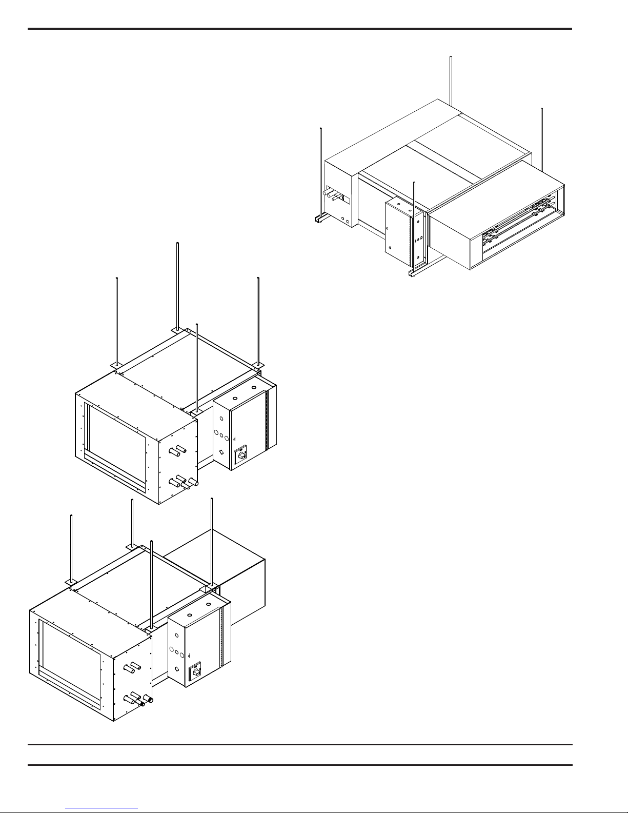
Fan Coil Unit Support Using Trapeze Suspension.
Care should be taken to prevent any materials such as paint,
plaster, drywall dust, and other construction materials from being
deposited in the drain pan, heater, coils, or on the motor or blower
wheels. Failure to do so may have negative effects on unit operation
and may result in premature failure. To prevent contamination, the
units should have some form of temporary covering placed over
them during construction.
For model series 35FH & 37FH; suspend the unit from the building
structure in a horizontal plane. Be careful not to obstruct the bottom
access panels with support channels or straps. When requested,
unit is supplied with field mounted hanger brackets for use with
hanger rod up to 3/8" (9.5) diameter. Hanger brackets or straps
should be screwed to the top corner posts, unit casing sides, or
alternatively onto the inlet and outlet ends of the unit. Fan coil
units are too heavy to suspend with the ductwork they must be
independently supported. For the 35FH Size 30 & 40 it is advised
that these units are mounted by a trapeze suspension. The unit
must be mounted level. The drain pan has a built-in slope to ensure
proper drainage. Field-furnished and installed accessories such
as ductwork, mixing boxes, economizers, dampers, and valve
packages must be independently supported and must not rely on
the unit for support.
After unit is mounted, the service connections such as water, drain
and electrical can be made. At this time it should be confirmed that
the proper types of service have been provided to the unit. The
water connections should be checked for line size, temperature,
and location. Electrical service to the unit should be compared to
the unit nameplate to verify compatibility. The routing, and sizing
of all piping, the type and sizing of all wiring and other electrical
components such as circuit breakers, disconnects switches, etc.
should be determined by the individual job requirements and should
not be based on the size or type connections provided with the
equipment. All installations should be made in compliance with all
governing codes and ordinances. This compliance to all codes is
the responsibility of the installing contractor.
Fan Coil Unit Support Using Hanger Brackets and Rods.
Engineered Comfort reserves the right to change any information concerning product or specification without notice or obligation.
Dimensions are in inches (mm).
Page 2 of 410/18 EC-35FH-37FH-INST
 Loading...