

Engineered air DJ Series, DJE Series, DJS Series, DG Series Installation, Operation And Maintenance Manual
A
INSTALLATION, OPERATION
AND MAINTENANCE MANUAL
FOR
DJ(E,S) & DG SERIES
INDIRECT GAS OR OIL FIRED HEATING UNITS
INDOOR AND OUTDOOR MODELS
UNIT MODEL NO. _________________
UNIT SERIAL NO. _________________
SERVICED BY: ___________________
TEL. NO: ________________________
CANADIAN
HEAD OFFICE
AND FACTORY
1401 HASTINGS CRES. SE
CALGARY, ALBERTA
Ph: (403) 287-4774
Fx: 888-364-2727
32050 W. 83rd STREET
T2G 4C8
AND FACTORY
DESOTO, KANSAS
Ph: (913) 583-3181
Fx: (913) 583-1406
SALES OFFICES ACROSS CANADA AND USA
Retain instructions with unit and maintain in a legible condition.
Please give model number and serial number when contacting
factory for information and/or parts.
www.engineeredair.com
USA
HEAD OFFICE
66018
CANADIAN
EASTERN FACTORY
1175 TWINNEY DRIVE
NEWMARKET, ONTARIO
L3Y 5V7
Ph: (905) 898-1114
Fx: (905) 898-7244
May 12 R2

A DJ & DG MANUAL
TABLE OF CONTENTS
YOU HAVE RESPONSIBILITIES TOO................................................................................................ ............................................... 3
INTRODUCTION................................................................................................................................................................................ 3
SAFETY PRECAUTIONS................................................................................................................................ ................................... 3
WARRANTY ....................................................................................................................................................................................... 4
PARTS................................................................................................................................................................................................ 5
RECEIVING........................................................................................................................................................................................ 5
TEMPORARY STORAGE .................................................................................................................................................................. 5
INSTALLATION.................................................................................................................................................................................. 6
CODES............................................................................................................................................................................................... 6
MINIMUM CLEARANCE TO COMBUSTIBLES AND FOR SERVICE IN INCHES (mm).................................................................... 7
LIFTING.............................................................................................................................................................................................. 8
MOUNTING ........................................................................................................................................................................................ 8
SHIPPING MATERIALS................................................................................................................................................................ ..... 9
ASSEMBLY........................................................................................................................................................................................ 9
PIPING, ELECTRICAL OR CONTROL SERVICE CONNECTIONS................................................................................................. 10
NATURAL GAS AND PROPANE INSTALLATION:.......................................................................................................................... 10
GAS LINE TESTING (EXTERNAL TO THE UNIT)........................................................................................................................... 11
OIL INSTALLATION ......................................................................................................................................................................... 11
HEAT EXCHANGER CONDENSATE DRAIN ON INDOOR UNITS................................................................................................. 11
VENTING PRODUCTS OF COMBUSTION ..................................................................................................................................... 12
DUCT FURNACE INSTALLATION................................................................................................................................................... 13
PIPING, ELECTRICAL OR CONTROL SERVICE CONNECTIONS................................................................................................. 13
ELECTRICAL INSTALLATION......................................................................................................................................................... 13
Recommended 24V Field Wiring Size:............................................................................................................................................. 14
DUCT MOUNTED TE-6000-EA3 TEMPERATURE SENSOR.......................................................................................................... 15
COIL CONNECTIONS...................................................................................................................................................................... 15
DRAIN TRAPS.................................................................................................................................................................................. 16
FLUSHING AND DEGREASING OF WATER AND GLYCOL COILS............................................................................................... 16
HEAT TRANSFER FLUIDS .............................................................................................................................................................. 17
BEFORE START-UP................................ ........................................................................................................................................ 17
START-UP CHECK LIST.................................................................................................................................................................. 17
OPERATION .................................................................................................................................................................................... 19
SAFETY SHUTOFF VALVE LEAK TEST:........................................................................................................................................ 20
GAS MANIFOLD............................................................................................................................................................................... 20
OPERATIONAL CHECK FOR ALL GAS FIRED DJ & DG UNITS................................ .................................................................... 21
OPERATIONAL CHECK FOR ALL OIL FIRED DJ & DG UNITS ..................................................................................................... 22
COMBUSTION AND FINAL UNIT CHECK FOR UNITS WITHOUT TRAC CONTROLS ................................................................. 23
ELECTRODE DETAIL...................................................................................................................................................................... 24
UNIT SHUT-DOWN INSTRUCTIONS .............................................................................................................................................. 24
Service Shut Down........................................................................................................................................................................... 24
Emergency Shut Down..................................................................................................................................................................... 25
Start-Up After Extended Shut-Down Period................................ ...................................................................................................... 25
CONTROL SETTINGS ..................................................................................................................................................................... 25
MAINTENANCE................................................................................................................................................................................25
ELECTRICAL ................................................................................................................................................................................... 26
BELT ADJUSTMENT........................................................................................................................................................................ 26
SET SCREWS.................................................................................................................................................................................. 27
BEARING SETSCREW TORQUES.................................................................................................................................................. 27
LUBRICATION OF FAN BEARINGS................................................................ ................................................................................ 27
LUBRICATION OF DODGE FAN BEARINGS.................................................................................................................................. 28
MOTOR LUBRICATION ................................................................................................................................................................... 29
GAS MANIFOLD............................................................................................................................................................................... 30
GAS BURNERS................................................................................................................................................................................ 30
OIL BURNERS ................................................................................................................................................................................. 30
VENT TERMINALS........................................................................................................................................................................... 30
FILTERS........................................................................................................................................................................................... 30
CONTROLS...................................................................................................................................................................................... 31
CONTROL ENCLOSURE VENTILATION ........................................................................................................................................ 31
OUTDOOR AIR INTAKES, MIXING SECTIONS AND DAMPERS................................................................................................... 31
COILS............................................................................................................................................................................................... 31
© Airtex Manufacturing Partnership. All rights reserved.
2 of 34 May 12 R2
A DJ & DG MANUAL
YOU HAVE RESPONSIBILITIES TOO
This installation, operation and maintenance manual can not cover every possibility, situation or
eventuality. Regular service, cleaning and maintaining the equipment is necessary. If you are not capable
of performing these tasks, hire a qualified service specialist. Failure to perform these duties can cause
property damage and/or harm to the building occupants and will void the manufacturers’ warranty.
INTRODUCTION
Engineered Air units are high quality products designed and manufactured to provide many years of
trouble-free operation. We recommend that this manual be read thoroughly to ensure proper installation,
efficient operation and proper maintenance of this equipment. The submittal record is considered to be
part of the Installation, Operation and Maintenance Manual. Please report any omissions to the national
service manager.
SAFETY PRECAUTIONS
Read, understand and follow the complete manual before beginning the installation, including all safety
precautions and warnings.
mhg WARNING:
FIRE OR EXPLOSION HAZARD
Failure to follow safety warnings exactly could result in serious injury, death or property
damage.
Be sure to read and understand the installation, operation and service instructions in this
manual.
Improper installation, adjustment, alteration, service or maintenance can cause serious
injury, death or property damage.
— Do not store or use gasoline or other flammable vapors and liquids in the vicinity of this
or any other appliance.
— WHAT TO DO IF YOU SMELL GAS
· Do not try to light any appliance.
· Do not touch any electrical switch; do not use any phone in your building.
· Leave the building immediately.
· Immediately call your gas supplier from a phone remote from the building. Follow
the gas supplier’s instructions.
· If you cannot reach your gas supplier, call the fire department.
— Installation and service must be performed by a qualified installer, service agency or the
gas supplier.
3 of 34 May 12 R2
A DJ & DG MANUAL
Warning:
m
Warning:
m
c
WARRANTY
LIMITED WARRANTY ENGINEERED AIR will furnish without charge, F.O.B. factory, freight collect,
replacement parts for, or repairs to products covered herein which prove defective in material or
workmanship under normal and proper use for a period of twelve (12) months from the initial start-up or
eighteen (18) months from the date of shipment, whichever expires sooner, provided the customer gives
ENGINEERED AIR written notice of such defects within such time periods and provided that inspection by
ENGINEERED AIR establishes the validity of the claim and all pertinent invoices have been paid in full.
The repairs or replacements will be made only when the complete product(s) or part(s) claimed to be
defective are returned to ENGINEERED AIR or a depot designated by ENGINEERED AIR, transportation
charges prepaid. Repairs or replacements as provided for by this paragraph shall constitute fulfillment of
all ENGINEERED AIR's obligations with respect to this warranty. The refrigerant charge is not included in
any part of this warranty. This warranty does not apply to any products or parts thereof that have been
subject to accident, misuse or unauthorized alterations, or where ENGINEERED AIR's installation and
service requirements have not been met.
The foregoing warranty is in lieu of all other warranties, express or implied. ENGINEERED AIR specifically
disclaims any implied warranty of merchantability and/or fitness for purpose. Under no circumstances shall
ENGINEERED AIR be liable to, nor be required to indemnify, Buyer or any third parties for any claims,
losses, labour, expenses or damages (including special, indirect, incidental, or consequential damages) of
any kind, resulting from the performance (or lack thereof) of this Agreement or the use of, or inability to use
the goods sold hereunder, including, but not limited to, damages for delay, temporary heating/cooling
costs, loss of goodwill, loss of profits or loss of use. Furthermore, the parties agree that the Buy e r's sole
remedy under this Agreement shall be limited to the limited warranty set forth in the preceding paragraph
relating to the repair or replacement of any defective goods. Under no circumstances shall any claim or
award against ENGINEERED AIR exceed the original contract price whether awarded through arbitration,
litigation or otherwise.
ENGINEERED AIR Warranty is void if:
1. The unit is not installed in accordance with this manual.
2. The start-up and operation of the unit is not performed in accordance with this manual.
3. The unit is operated in an atmosphere containing corrosive substances.
4. The unit is allowed to operate during building construction.
5. The unit is allowed to operate in atmospheres where chlorine or chlorine compounds are present or
which contain any contaminant (silicone, aluminum oxide etc.) that adheres to the spark ignition
flame sensing probe.
Pool, laundry and common cleaning products often contain fluorine or
chlorine compounds. When these chemicals pass through the heater,
they can form strong acids. The acid can eat through the heat
exchanger wall, causing serious damage and presenting a possible
threat of flue gas spillage into the building.
This unit is connected to high voltages. Electrical shock or death could occur
if instructions are not followed. This equipment contains moving parts that
can start unexpectedly. Injury or death could occur if instructions are not
followed. All work should be performed by a qualified technician. Always
disconnect and lock out power before servicing. DO NOT bypass any
interlock or safety switches under any circumstances.
4 of 34 May 12 R2

A DJ & DG MANUAL
PARTS
Warning:
mc
hg
1. Motors:
Motor manufacturers have service centers that will repair or replace motors as required.
2. Parts Other Than Motors:
Contact the nearest Engineered Air sales office or factory. Be sure to include Model Number,
Serial Number, date of installation and nature of fail ure along with the description of the parts
required. Some parts may not be stocked items that must be made or ordered.
RECEIVING
Refer to the back of the packing slip for receiving unit instructions.
On receipt of the unit, check for damage. Inspect protective covers for punctures or other signs that there
may be internal damage. Remove protective covers and check for internal damage. Replace covers if the
unit is not being assembled or installed at this time. Open access doors and check for internal damage.
Close access doors when the inspection is complete.
All units are pre-tested at the factory immediately prior to shipping and are ensured to be in good operating
condition at that time. If damage is found follow the instructions on the packing slip.
On receipt of the unit, check electrical characteristics (see rating plate) to make sure the unit voltage is
compatible with that available for the unit. All parts for field installation are listed on the shipping order form.
Any replacement part must be of equivalent listing or certification and be
functionally equivalent. The replacement part must meet the original’s
specification in terms of functionality including certifications, timing, input
and output range, accuracy and operation.
Failure to replace parts or components with equivalent parts can cause
property damage, injury or death.
TEMPORARY STORAGE
If a unit is to be stored prior to installation the following precautions are required:
• Store in a well drained area that will not accumulate surface water.
• Store in an area where the unit will not get damaged.
• The entire perimeter and any full height cross members of the unit must be supported by a level
surface and the supporting surface must be adequate for supporting the entire weight of the unit.
• All protective coverings that were provided for shipping must be in place.
• Protect indoor units from rain and snow.
5 of 34 May 12 R2
A DJ & DG MANUAL
INSTALLATION
Warning:
m g
Caution:
m
Note: Installation shall be in accordance with this manual and all other associated component and
control Installation, Operation and Maintenance Manuals.
Only equipment bearing a CSA C22.2 No. 213 or UL 1604 rating plate (label)
with an accompanying CSA Certification mark is suitable for installation in
a hazardous location. The hazardous location must conform with the Class,
Division, Group and temperature code (if shown) displayed on the rating
plate (label).
If not marked as noted above, the unit is not rated for hazardous locations
and should not be installed in areas requiring any hazardous location
rating.
All wiring, piping and fuel line installation must be completed by qualified
persons in accordance with all federal, state, provincial and/or local codes.
CODES
In Canada:
1. The installation of this unit shall be in accordance with the latest edition of the Canadian Electrical
Code, Part 1 – C.S.A. Standard C22.1, Provincial and Local Codes, and in accordance with the
local authorities having jurisdiction.
2. This unit shall be electrically grounded in accordance with the latest edition of the Canadian
Electrical Code, Part 1 – C.S.A. Standard C22.1, Provincial and Local Codes, and in accordance
with the local authorities having jurisdiction.
3. The installation of this unit shall be in accordance with the latest edition of the Canadian Natural
Gas and Propane Installation Code, C.S.A. Standard B149.1, Provincial and Local Codes, and in
accordance with the local authorities having jurisdiction.
4. In accordance with local authorities having jurisdiction or CSA. Standard B149.1 a readily
accessible approved manual shut-off valve shall be installed in either the drop or riser as close as
possible to the valve train (gas manifold).
5. The installation of this unit shall be in accordance with the latest edition of the National Plumbing
Code of Canada, Provincial and Local Codes, and in accordance with the local authorities having
jurisdiction.
6. The installation of this unit shall be in accordance with all other National, Provincial and Local
Codes, and in accordance with the local authorities having jurisdiction.
In USA:
1. The installation of this unit shall be in accordance with the latest edition of the National Electrical
Code (ANSI/NFPA 70), State and Local Codes and in accordance with the local authorities having
jurisdiction.
6 of 34 May 12 R2
A DJ & DG MANUAL
2. This unit shall be electrically grounded in accordance with the latest edition of the National
Electrical Code (ANSI/NFPA 70), State and Local Codes and in accordance with the local
authorities having jurisdiction.
3. If the unit has not been provided with an electric disconnect switch, one of adequate ampacity shall
be installed in accordance with Article 430 of the National Electrical Code (ANSI/NFPA 70).
4. The installation of this unit shall be in accordance with the latest edition of the National Fuel Gas
Code ANSI/Z223.1/NFPA 54, State and Local Codes and in accordance with the local authorities
having jurisdiction.
5. In accordance with local authorities having jurisdiction or NFPA 54 an accessible approved manual
shutoff valve shall be installed within 6 ft (1.8 m) of the valve train (gas manifold).
6. The installation of this unit shall be in accordance with the latest edition of the National Standard
Plumbing Code (NSPC), State and Local Codes and in accordance with the local authorities having
jurisdiction.
7. The installation of this unit shall be in accordance with all other National, State and Local
Codes, and in accordance with the local authorities having jurisdiction.
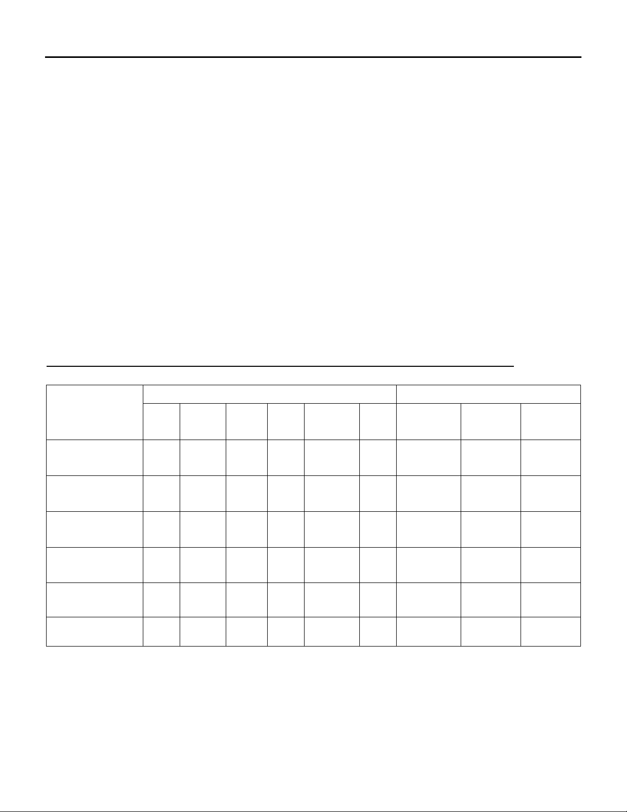
MINIMUM CLEARANCE TO COMBUSTIBLES AND FOR SERVICE IN INCHES (mm)
COMBUSTIBLE CLEARANCE SERVICE CLEARANCE
MODEL
DJ(E,S) INDIRECT
FIRED GAS HEAT
DG INDIRECT
FIRED GAS HEAT
INDIRECT FIRED
OIL HEAT
FLUID COILS &
RECOVERY
DEVICES
ELECTRIC HEAT
OTHER (NON
GAS) UNITS
TOP FRONT BACK SIDE BOTTOM FLUE
6"
(152)
6"
(152)
6"
(152)
1"
(25)
1"
(25)
1"
(25)
6"
(152)
6"
(152)
6"
(152)
1"
(25)
1"
(25)
1"
(25)
6"
(152)
6"
(152)
6"
(152)
1"
(25)
6"
(152)
1"
(25)
1"
(25)
1"
(25)
1"
(25)
1"
(25)
1"
(25)
1"
(25)
0
0
0
0 NA NA
0 NA NA
0 NA NA 24" (610) 42" (1067)
9"
(229)
9"
(229)
9"
(229)
OPPOSITE
BURNER
SIDE
NA 24" (610) 42" (1067)
NA 24" (610) 42" (1067)
18"
(457)
† - As required by the Canadian Electrical Code or the National Electrical Code.
For Safety and Service, the minimum clearances must be observed. Minimum clearances also provide
adequate combustion air supply.
SERVICE/
BURNER
SIDE
24" (610) 42" (1067)
UNIT
WIDTH
UNIT
WIDTH
+ 10" (254)
CONTROL
PANEL †
42" (1067)
42" (1067)
7 of 34 May 12 R2
A DJ & DG MANUAL
LIFTING
Engineered Air units are constructed on a structural steel base frame. The unit base frame is equipped with
lifting lugs specifically located to facilitate proper lifting of the unit. Spreader bars must be used to keep
rigging away from the unit cabinetry. All lifting lugs must be used. If using a lift truck, ONLY lift using the
perimeter structural frame. DO NOT allow forks to lift on cabinet or unit floor.
Note: There may be bottom mounted components, such as drain piping, that can be easily damaged.
Warning:
m
MOUNTING
Units must be mounted level. Failure to do so can cause water to be trapped in drain pans or operational
problems that can void warranty. Failure to do so can result in injury or death, damage the equipment
and/or building and can be a cause of poor indoor air quality.
Equipment must be installed so that sufficient working clearance and component access is provided.
Some units are designed for cantilevered installation. Consult the Submittal Record for specific unit
mounting.
Consult the Submittal Record for specific unit mounting. Engineered Air units are constructed for three
types of mounting:
1. Base mounting – Consult the Submittal Record for type of mounting. Unless the unit is specifically
designed for point or other mounting, the base of the unit must be supported continuously by a
mounting support system that is directly below the unit structural base frame and runs the entire
length and width of the unit. Refer to the Submittal Record for mounting information. Units 100”
(2500mm) wide and under can be supported on each side continuously along the length of the unit.
As a minimum, sleepers that are installed perpendicular to the length of the unit must be continuous
across the width of the unit and shall be installed at the end lifting point base rails and the lesser of
80” (2000mm) on center or at all lifting points.
2. Suspended mounting – Where units have been designed for suspended mounting, factory provided
connections for hanger rods will be provided. All hanger rod supports mus t be used. Suspended
units must be protected from damage. When installed in aircraft hangers, parking garages or
repair garages the installation must comply where applicable with:
a) The Canadian Natural Gas and Propane Installation Code, C.S.A. Standard B149.1
b) The Standard on Aircraft Hangers, ANSI/NFPA 409
c) The Standard on Parking Garages, ANSI/NFPA 88A
d) The Standard on Repair Garages, ANSI/NFPA 88B
3. Roof curb mounting – The curbs are constructed of heavy gauge load bearing, galvanized steel,
and must be fully insulated after installation. Wood nailer strips are provided for easy attachment of
roof flashing. Gasket material is supplied with the unit and must be field mounted on the curb to
seal the joint between the curb and the unit frame. The curb must be supported along its entire
perimeter and any full height cross members as shown on the shop drawings. Point loading of
curbs is not permissible.
Injury or death can result from improper rigging and lifting. Rigging and
lifting of equipment must be performed by qualified personnel with proper
equipment using appropriate and approved safety precautions.
8 of 34 May 12 R2
A DJ & DG MANUAL
The gasket material provided for the curb is closed cell foam. Closed cell foam is dense and does
not compress easily. If the unit is split and shipped in sections there will also be gasket material for
sealing between sections. The gasket material for splits is open cell foam. It is less dense than the
closed cell foam and compresses easily.
ONLY USE THE CLOSED CELL FOAM GASKET PROVIDED FOR SEALING THE CURB.
Curbs may be broken down for shipping. Field assembly is required by the installing contractor. Bolt
all sections together at split joints using hardware provided. The installing contractor must caulk and
seal all joint and corner flashings. All flashings and braces that are provided must be installed. DO
NOT screw/penetrate joint, corner or adaptor flashings. Refer to assembly instructions sent with
roof curb.
SHIPPING MATERIALS
Remove shipping materials. Shipping materials may include, but are not limited to:
• Protective covers over openings, inlets, condenser coils etc.
• Protective covers over split sections if provided.
• Tie-down bolts, straps and blocks on fan and compressor vibration isolators.
• Tie-down bolts, straps and blocks on tilt equipped heat pipes and enthalpy/desiccant wheels if
supplied.
• Indirect fired heat exchangers may be supported with wood for shipping. Remove.
ASSEMBLY
Warning:
Assembly of split units requires bolting together the base frame of adjacent
sections. This may require personnel to work under the unit during
assembly. Injury or death can result from improper support or improper
m
loading of the curb. Additional temporary support shall be provided by the
installer for the safety of personnel.
If the unit is split and shipped in sections, the sections must be field assembled. All sections are pre-drilled
for assembly. The hardware and gaskets are packed in one of the sections. Apply the gasket, align the
sections. The base frame must be bolted together first. Access below the un it for bolting of the base frame
must be provided. Once the base frame has been tightly fastened, loosely assemble all the bolts and nuts,
and then tighten. Caulk all split lines. Install split joint caps. The inlet hood is designed for field installation.
On outdoor units connect the hood to the support flange and attach with appropriate fasteners. Connect all
wiring on units that had been split for shipment.
The gasket material provided for the split is open cell foam. Open cell foam is light and compresses easily.
If the unit is mounted on a curb provided by Engineered Air there will also be gasket material for sealing
the curb. The gasket material for curbs is closed cell foam. It is more dense than open cell foam and does
not compress as easily.
ONLY USE THE OPEN CELL FOAM GASKET PROVIDED FOR SEALING THE SPLIT(S).
SPLIT UNIT WIRING
All split wiring must be completed by an electrician prior to starting the equipment. A number of different
methods are used to reconnect the wiring.
Power wire: this wiring is generally not broken or spliced, and will extend from the device back to the
contactor or terminal block inside the electrical panel(s). The wire will be tagged to identify which panel it
extends to and will be numbered to the corresponding connection.
9 of 34 May 12 R2

A DJ & DG MANUAL
The location of the equipment split line may result in the wire being disconnected at the device it is feeding.
The wire bundle will be tagged and identi fied. Confirm correct rotation of 3 phase devices after the wiring
connections has been completed.
Control wire: this wire is typically broken near the split line, to be reconnected at either a enclosed terminal
block, junction box or extended to a nearby control panel. Each wire or wire bundle will be tagged and
numbered to indicate the location it is sent to.
Sensor wire shield: The drain wire from the shield must be grounded (at one end only). A ground
connection point is available for connection at the point of termination.
All loose wiring must be securely fastened to the equipment casing upon completion.
PIPING, ELECTRICAL OR CONTROL SERVICE CONNECTIONS
DO NOT install anything that will interfere with equipment access or the rating plate.
Engineered Air equipment is constructed with cabinet and floors designed to prevent water from entering
the building through the installed unit. When ordered, factory installed pipe chases and/or electrical chases
are built into the unit floor. Factory chases are provided with covers that need to be replaced and sealed
after piping and electrical connections are made.
THE FLOOR OF THE UNIT HAS BEEN MADE WATER-RESISTANT. DO NOT CUT OR DRILL HOLES
IN THE FLOOR OR USE PENETRATING FASTENERS.
All penetrations through the unit walls must be caulked and sealed to prevent air and/or water from
entering the unit.
NATURAL GAS AND PROPANE INSTALLATION:
1. Installation must be made in accordance with the requirements of the authorities having jurisdiction.
2. Check the unit rating plate and confirm fuel type, supply pressure, input rating and temperature rise.
3. Refer to the heater rating plate for determining the minimum gas supply pressure for obtaining the
maximum gas capacity for which this heater is specified.
4. Gas supply pressure higher than the unit rating plate requires an additional field supplied gas regulator.
5. Install an approved appliance shutoff valve on the gas supply in accordance with the requirements of
the authorities having jurisdiction.
6. Gas lines shall not interfere with unit access. The gas line connection at the heater shall have an
approved drip leg with screwed cap.
7. A minimum 1/8 inch NPT plugged tapping, accessible for test gauge connection, must be installed
immediately upstream of the gas supply connection to the unit.
8. On indoor units any control device (regulator, diaphragm valve, high and low pressure switch, etc.) that
requires a bleed or vent line, must be vented in accordance with applicable codes.
10 of 34 May 12 R2

A DJ & DG MANUAL
GAS LINE TESTING (EXTERNAL TO THE UNIT)
The appliance and its individual shutoff valve must be disconnected from the gas supply piping system
during any testing of that system at test pressures in excess of 0.5 psi (3.5 kPa).
The appliance must be isolated from the gas supply system by closing its individual shutoff valve during
any testing of that system at test pressure equal to or less than 0.5 psi (3.5 kPa).
OIL INSTALLATION
Installation must be made in accordance with NFPA 31 or CSA B139 and with the requirements of
authorities having jurisdiction.
1. Check the unit name plate and confirm fuel type and input rating.
2. The heaviest fuel oil type is marked on the unit name plate.
3. The unit is to be supplied with an adequate flow of clean, air free fuel oil at a minimum temperature
of 32°F (0°C) at a neutral pressure. This requirement can be met if the oil is supplied to the unit
from an indoor day tank with a gravity supply.
4. All oil piping to the heater must be installed in accordance with good piping practices. (See
supplemental piping information bulletin from the burner manufacturer).
5. All oil burners should have an oil return line.
6. Oil fired heaters MUST use “A” vent.
7. OIL-FIRED APPLIANCES SHALL BE CONNECTED TO VENTS HAVING SUFFICIENT DRAFT AT
ALL TIMES TO ENSURE SAFE AND PROPER OPERATION OF THE APPLIANCE.
HEAT EXCHANGER CONDENSATE DRAIN ON INDOOR UNITS
The drain must be installed in accordance with all plumbing codes.
The condensate is to be drained with minimum 1/2” (13 mm) nominal drain line, of material suitable for
corrosive condensate, to an indirect drain connection.
11 of 34 May 12 R2
 Loading...