

Engine distributors DSG-423 Service Manual
DSG-423
2.3 LITER
INDUSTRIAL ENGINE SERVICE MANUAL
Powertrain Assemblies
& Components Provided
By Ford Component Sales
EDI 1060040
AUG, 2007

Section 01
GENERAL INFO
Section
Index
Reproduction in any manner, in whole or in part, is
prohibited without the express permission in
writing from:
Section 02
Section 03
Section 04
Section 05
Section 06
ENGINE
IGNITION
FUEL
COOLING
CHARGING
Engine Distributors Inc (EDI)
EDI policy is one of continuous improvement and while
every effort is made to ensure that this publication is up
to date and correct in all respects, the right to change
prices, specifications and equipment at any time without
notice is reserved. Accordingly this publication is not to
be regarded as a final description of any individual
engine.
Section 07
Section 08
Section 09
Section 10
STARTER
ENG. CONTROLS
METRICS
DISTRIBUTORS
HEALTH & SAFETY
WARNING: THE FOLLOWING HEALTH AND SAFETY RECOMMENDATIONS SHOULD BE
CAREFULLY OBSERVED
WARNING: CARRYING OUT CERTAIN OPERATIONS AND HANDLING SOME
SUBSTANCES CAN BE DANGEROUS OR HARMFUL TO THE OPERATOR IF THE
CORRECT SAFETY PRECAUTIONS ARE NOT OBSERVED. SOME SUCH PRECAUTIONS
ARE RECOMMENDED AT THE APPROPRIATE POINTS IN THIS BOOK.
WARNING: WHILE IT IS IMPORTANT THAT THESE RECOMMENDED SAFETY
PRECAUTIONS ARE OBSERVED, CARE NEAR MACHINERY IS ALWAYS NECESSARY,
AND NO LIST CAN BE EXHAUSTIVE. ALWAYS BE CAUTIOUS TO AVIOD POTENTIAL
SAFETY RISKS.
The following recommendations are for general guidance:
1. Always wear correctly fitting protective clothing which should be laundered regularly. Loose or baggy clothing
can be extremely dangerous when working on running engines or machinery. Clothing which becomes
impregnated with oil or other substances can constitute a health hazard due to prolonged contact with the skin
even through underclothing.
2. So far as practicable, work on or close to engines or machinery only when they are stopped. If this is not
practicable, remember to keep tools, test equipment and all parts of the body well away from the moving parts
of the engine or equipment—fans, drive belts and pulleys are particularly dangerous. The electric cooling fan
used on some installations is actuated automatically when the coolant reaches a specified temperature. For this
reason, care should be taken to ensure that the ignition/isolating switch is OFF when working in the vicinity of
the fan as an increase in coolant temperature may cause the fan suddenly to operate.
3. Avoid contact with exhaust pipes, exhaust manifolds and silencers when an engine is, or has recently been
running; these can be very hot and can cause severe burns.
4. Many liquids used in engines or vehicles are harmful if taken internally or splashed into the eyes. In the event of
accidentally swallowing gasoline (petrol), oil, diesel fuel, antifreeze, battery acid etc, do NOT encourage vomiting
and OBTAIN QUALIFIED MEDICAL ASSISTANCE IMMEDIATELY.
Wear protective goggles when handling liquids which are harmful to the eyes; these include ammonia and battery
acid. If any of these substances are splashed in the eyes, wash out thoroughly with clean water and OBTAIN
QUALIFIED MEDICAL ASSISTANCE IMMEDIATELY.
WARNING:
WARNING: ENGINE EXHAUST, SOME OF ITS CONSTITUENTS, AND
CERTAIN VEHICLE COMPONENTS CONTAIN OR EMIT CHEMICALS KNOWN
TO THE STATE OF CALIFORNIA TO CAUSE CANCER AND BIRTH DEFECTS
OR OTHER REPRODUCTIVE HARM. IN ADDITION, CERTAIN FLUIDS
CONTAINED IN VEHICLES AND CERTAIN PRODUCTS OF COMPONENT
WEAR CONTAIN OR EMIT CHEMICALS KNOWN TO THE STATE OF
CALIFORNIA TO CAUSE CANCER AND BIRTH DEFECTS OR OTHER
REPRODUCTIVE HARM.
IMPORTANT SAFETY NOTICE
Appropriate service methods and proper repair procedures are essential for the safe, reliable operation of all
industrial engines as well as the personal safety of the individual doing the work. This Service Manual provides
general directions for accomplishing service and repair work with tested, effective techniques. Following them will
help assure reliability.

INDEX
DSG-423 GENERAL INFORMATION
Subject Page
General Information
Introduction ............................................................................................................................................... 01 - 3
Safety Notice ............................................................................................................................................. 01 - 3
Notes, Cautions, and Warnings................................................................................................................. 01 - 3
Battery Handling and Charging ................................................................................................................. 01 - 4
Forward ..................................................................................................................................................... 01 - 5
Engine Identification .................................................................................................................................. 01 - 5
Parts and Service ...................................................................................................................................... 01 - 5
Description and Operation......................................................................................................................... 01 - 5
Diagnosis and Testing
Special Tools............................................................................................................................................. 01 - 6
Inspection and Verification ........................................................................................................................ 01 - 7
Symptom Chart ......................................................................................................................................... 01 - 7
PCV System Malfunction......................................................................................................................... 01 - 10
Engine Oil Leaks ..................................................................................................................................... 01 - 10
Compression Tests ................................................................................................................................. 01 - 12
Cylinder Leakage Detection .................................................................................................................... 01 - 13
Intake Manifold Vacuum Test.................................................................................................................. 01 - 13
Excessive Engine Oil Consumption ........................................................................................................ 01 - 15
Oil Pressure Test..................................................................................................................................... 01 - 16
Valve Train Analysis – Static................................................................................................................... 01 - 17
Valve Train Analysis – Dynamic.............................................................................................................. 01 - 17
Camshaft Lobe Lift .................................................................................................................................. 01 - 18
Hydraulic Valve Lash Adjuster ................................................................................................................ 01 - 20
01
General Service Procedures
Camshaft Journal Diameter..................................................................................................................... 01 - 21
Camshaft Journal Clearance................................................................................................................... 01 - 21
Camshaft Lobe Surface........................................................................................................................... 01 - 21
Camshaft Lobe Lift .................................................................................................................................. 01 - 22
Camshaft Runout .................................................................................................................................... 01 - 22
Camshaft End Play.................................................................................................................................. 01 - 22
Crankshaft Main Bearing Journal Diameter ............................................................................................ 01 - 23
Crankshaft Main Bearing Journal Taper.................................................................................................. 01 - 23
Crankshaft Main Bearing Journal Clearance........................................................................................... 01 - 24
Bearing Inspection .................................................................................................................................. 01 - 24
Crankshaft End Play................................................................................................................................ 01 - 25
Crankshaft Runout .................................................................................................................................. 01 - 25
Cylinder Bore Taper ................................................................................................................................ 01 - 25
Cylinder Bore Out-of-Round.................................................................................................................... 01 - 26
Piston Inspection..................................................................................................................................... 01 - 26
Piston Diameter....................................................................................................................................... 01 - 26
Piston to Cylinder Bore Clearance .......................................................................................................... 01 - 26
Piston Selection ...................................................................................................................................... 01 - 27
Piston Ring End Gap............................................................................................................................... 01 - 27
Piston Ring-to-Groove Clearance ........................................................................................................... 01 - 28
Crankshaft Connecting Rod Journal Diameter........................................................................................ 01 - 28
Crankshaft Connecting Rod Journal Taper ............................................................................................. 01 - 28
Connecting Rod Cleaning ....................................................................................................................... 01 - 28
Connecting Rod Larger End Bore ........................................................................................................... 01 - 29
Piston Pin Diameter................................................................................................................................. 01 - 29
Connecting Rod Bushing Diameter ......................................................................................................... 01 - 29
Connecting Rod Bend ............................................................................................................................. 01 - 29
01-1

DSG-423 GENERAL INFORMATION
INDEX (CONT.)
Subject Page
General Service Procedures
Connecting Rod Twist ............................................................................................................................. 01 - 29
Connecting Rod Piston Pin Side Clearance............................................................................................ 01 - 30
Connecting Rod Journal Clearance ........................................................................................................ 01 - 30
Bearing Inspection .................................................................................................................................. 01 - 31
Roller Follower Inspection ....................................................................................................................... 01 - 31
Hydraulic Lash Adjuster Inspection ......................................................................................................... 01 - 31
Valve Stem Diameter .............................................................................................................................. 01 - 32
Valve Stem-to-Valve Guide Clearance.................................................................................................... 01 - 32
Valve Inspection ...................................................................................................................................... 01 - 32
Valve Guide Inner Diameter .................................................................................................................... 01 - 33
Valve Guide Reaming ............................................................................................................................. 01 - 33
Valve Spring Installed Length.................................................................................................................. 01 - 33
Valve Spring Free Length........................................................................................................................ 01 - 33
Valve Spring Out-of-Square .................................................................................................................... 01 - 33
Valve Spring Compression Pressure ...................................................................................................... 01 - 34
Valve and Seat Refacing Measurements ................................................................................................ 01 - 34
Valve Seat Width..................................................................................................................................... 01 - 34
Valve Seat Runout .................................................................................................................................. 01 - 34
Flywheel Inspection................................................................................................................................. 01 - 35
Oil Pump Gear Radial Clearance............................................................................................................ 01 - 35
Oil Pump Rotor Inspection ...................................................................................................................... 01 - 35
Oil Pump Side Clearance........................................................................................................................ 01 - 35
Cylinder Bore Honing .............................................................................................................................. 01 - 36
Cylinder Bore Cleaning ........................................................................................................................... 01 - 36
Cylinder Block Repair - Cast Iron Porosity Defects................................................................................. 01 - 37
Cylinder Block Core Plug Replacement .................................................................................................. 01 - 37
Cylinder Head - Distortion ....................................................................................................................... 01 - 37
Spark Plug Thread Repair....................................................................................................................... 01 - 39
Exhaust Manifold Straightness................................................................................................................ 01 - 40
SPECIFICATIONS.......................................................................................................................................... 01 - 41
01-2
DSG-423 GENERAL INFORMATION
GENERAL INFORMATION
Introduction
This section covers various engine tests, adjustments,
service procedures and cleaning/inspection
procedures. Engine assembly and service
specifications appear at the end of the Section 02.
For engine disassembly, assembly, installation,
adjustment procedures and specifications, refer to
Section 02.
This engine incorporates a closed-type crankcase
ventilation system.
To maintain the required performance level, the fuel
system, ignition system and engine must be kept in
good operating condition and meet recommended
adjustment specifications.
Before replacing damaged or worn engine components
such as the crankshaft, cylinder head, valve guide,
valves, camshaft or cylinder block, make sure part(s) is
not serviceable.
WARNING: TO AVOID THE POSSIBILITY OF
PERSONAL INJURY OR DAMAGE, DO NOT
OPERATE THE ENGINE UNTIL THE FAN BLADE
HAS FIRST BEEN EXAMINED FOR POSSIBLE
CRACKS OR SEPARATION.
CAUTION: Use of abrasive grinding discs to remove
gasket material from the engine sealing surfaces
during repair procedures can contribute to engine
damage and wear. Airborne debris and abrasive grit
from the grinding disc may enter the engine
through exposed cavities causing premature wear
and eventual engine damage.
Engine Distributors Inc. (EDI) does not recommend
using abrasive grinding discs to remove engine gasket
material. Use manual gasket scrapers for removing
gasket material from the engine sealing surfaces.
Take added care to prevent scratching or gouging
aluminum sealing surfaces.
Safety Notice
There are numerous variations in procedures,
techniques, tools and parts for servicing equipment, as
well as in the skill of the individual doing the work. This
manual cannot possibly anticipate all such variations
and provide advice or cautions as to each. Accordingly,
anyone who departs from the instructions provided in
this Manual must first establish that neither personal
safety nor equipment integrity are compromised by the
choice of methods, tools or parts.
Notes, Cautions, and Warnings
As you read through the procedures, you will come
across NOTES, CAUTIONS, and WARNINGS. Each
one is there for a specific purpose. NOTES gives you
added information that will help you to complete a
particular procedure. CAUTIONS are given to prevent
you from making an error that could damage the
equipment. WARNINGS remind you to be especially
careful in those areas where carelessness can cause
personal injury. The following list contains some general
WARNINGS that you should follow when you work on
the equipment.
GENERAL WARNINGS:
TO HELP AVOID INJURY:
• ALWAYS WEAR SAFETY GLASSES FOR EYE
PROTECTION.
• USE SAFETY STANDS WHENEVER A
PROCEDURE REQUIRES YOU TO BE UNDER
THE EQUIPMENT.
• BE SURE THAT THE IGNITION SWITCH IS
ALWAYS IN THE OFF POSITION, UNLESS
OTHERWISE REQUIRED BY THE PROCEDURE.
• SET THE PARKING BRAKE (IF EQUIPPED)
WHEN WORKING ON THE EQUIPMENT. IF YOU
HAVE AN AUTOMATIC TRANSMISSION, SET IT
IN PARK (ENGINE OFF) OR NEUTRAL (ENGINE
ON) UNLESS INSTRUCTED OTHERWISE FOR A
SPECIFIC OPERATION. PLACE WOOD BLOCKS
(4”X 4” OR LARGER) TO THE FRONT AND REAR
SURFACES OF THE TIRES TO PROVIDE
FURTHER RESTRAINT FROM INADVERTENT
EQUIPMENT MOVEMENT.
• OPERATE THE ENGINE ONLY IN A WELL
VENTILATED AREA TO AVOID THE DANGER OF
CARBON MONOXIDE.
• KEEP YOURSELF AND YOUR CLOTHING AWAY
FROM MOVING PARTS WHEN THE ENGINE IS
RUNNING, ESPECIALLY THE FAN BELTS.
• TO PREVENT SERIOUS BURNS, AVOID
CONTACT WITH HOT METAL PARTS SUCH AS
THE RADIATOR, EXHAUST MANIFOLD, TAIL
PIPE, CATALYTIC CONVERTER AND MUFFLER.
• DO NOT SMOKE WHILE WORKING ON THE
EQUIPMENT.
• ALWAYS REMOVE RINGS, WATCHES, LOOSE
HANGING JEWELRY, AND LOOSE CLOTHING
BEFORE BEGINNING TO WORK ON THE
EQUIPMENT. TIE LONG HAIR SECURELY
BEHIND THE HEAD.
• KEEP HANDS AND OTHER OBJECTS CLEAR OF
THE RADIATOR FAN BLADES. ELECTRIC
COOLING FANS CAN START TO OPERATE AT
ANY TIME BY AN INCREASE IN UNDERHOOD
TEMPERATURES, EVEN THOUGH THE
IGNITION IS IN THE OFF POSITION.
THEREFORE, CARE SHOULD BE TAKEN TO
ENSURE THAT THE ELECTRIC COOLING FAN IS
COMPLETELY DISCONNECTED WHEN
WORKING UNDER THE HOOD.
01-3
DSG-423 GENERAL INFORMATION
Battery Handling and Charging
The handling and correct use of lead acid batteries is
not as hazardous provided that sensible precautions
are observed and that operatives have been trained in
their use and are adequately supervised.
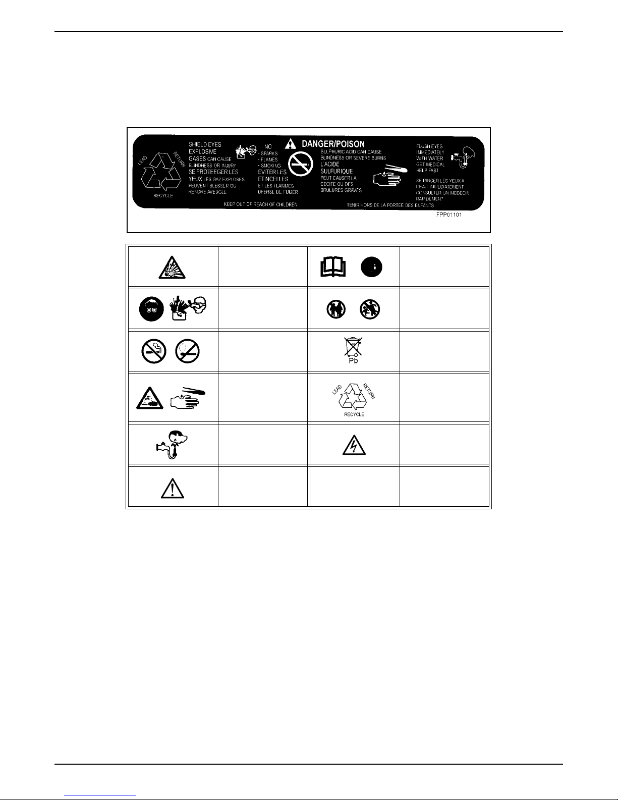
Typical Battery Labelling
Explosive gases
Eye protection must
be WORN.
No smoking or naked
flames.
It is important that all labelling on the battery is carefully
read, understood and complied with. The format of the
following symbols and labels is common to most brands
of lead acid battery.
Read relevant
instructions
Keep away from
children
Do not dispose of as
household waste.
Corrosive acid
Flush eyes
immediately when
contacted with acid
Caution/important
notice.
NOTE: Observe all manufacturers’ instructions when
using charging equipment.
CAUTION: Batteries should not be charged in the
vehicle or equipment. May damage electrical components.
Recycle (via
recognized disposal
system).
Electrical current may
cause injury to
personnel
01-4
DSG-423 GENERAL INFORMATION
Forward
This book contains service information for the engine(s)
listed on the title page.
The life of your engine unit and the delivery of the high
performance built into it will depend on the care it
receives throughout its life. It is the operator’s
responsibility to ensure that the engine is correctly
operated. We consider it to be in your interests to enlist
the aid of an authorized EDI Distributor, not only when
repairs are required but also for regular maintenance.
Distributors are listed at the back of this manual.
Engines manufactured by Ford Motor Company are
available through EDI Distributors. When in need of
parts or service, contact your local Authorized
Distributor. In overseas territories, in the event of
difficulties, communicate directly with the supervising
EDI affiliated Company in your area whose address
appears at the end of this book.
Where the terms “Right” or “Left” occur in this
publication, they refer to the respective sides of the
engine when viewed from the rear or flywheel end.
Pistons and valves are numbered from the front or
timing cover end of the engine commencing at No. 1.
You may find that your engine assembly includes
optional equipment not specifically covered in the
following text. Nevertheless, the service procedures
outlined in this book still apply to your engine.
Parts and Service
Replacement parts can be obtained through your local
EDI Distributor listed in the back portion of this manual.
They also may be found in the yellow pages under
“Engines” or contact EDI directly at 1 800 220 2700.
EDI Distributors are equipped to perform major and
minor repairs. They are anxious to see that all of your
maintenance and service needs are quickly and
courteously completed.
Description and Operation
Section 01 of this manual covers general procedures
and diagnosis of the engine system, including base
engine repair procedures, that would be common to
most engines. Refer to Section 02 for more specific
service information on the DSG-423 engine.
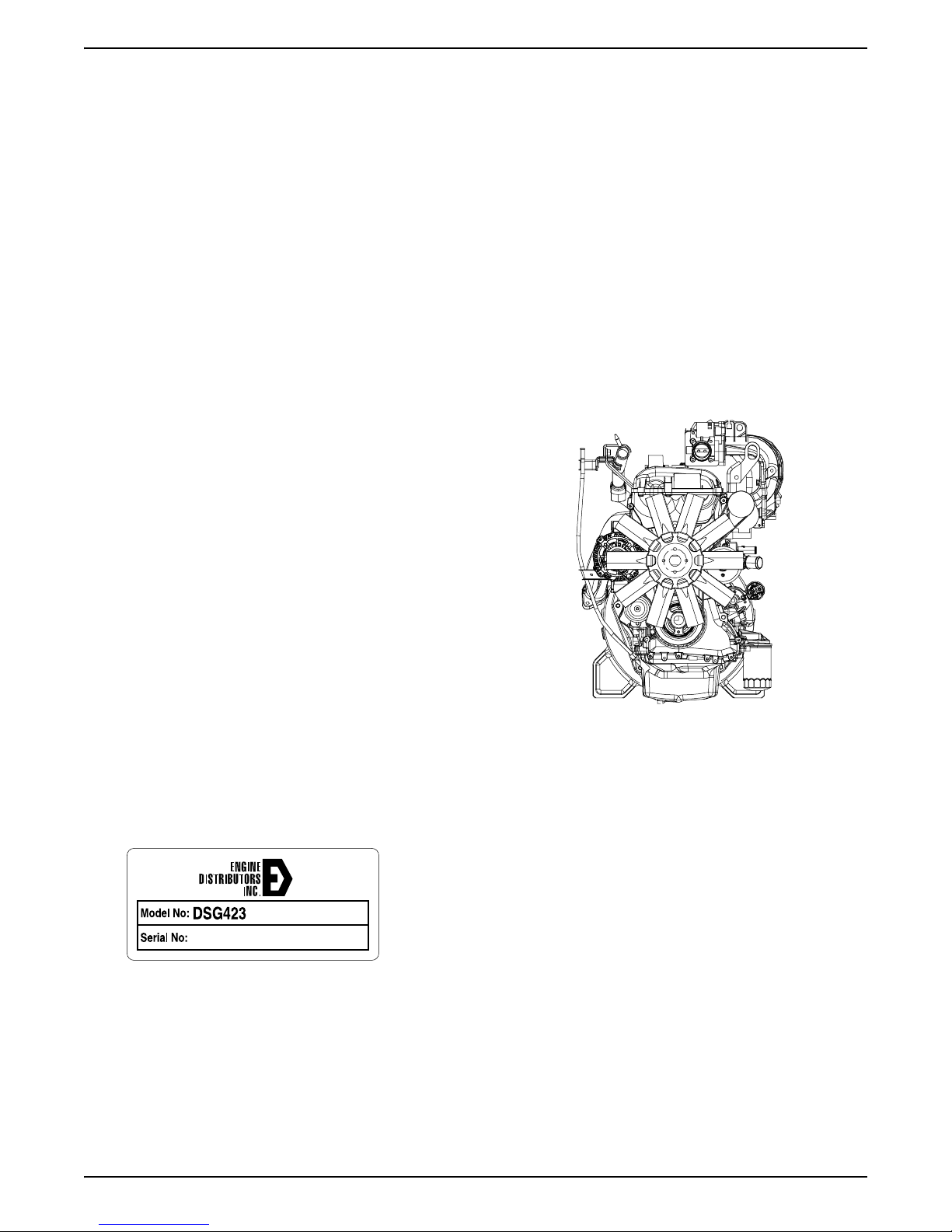
Engine Identification
Because Ford Power Products markets such a wide
range of industrial gasoline and diesel engines manufactured both in the U.S. and overseas - it is
important that you have as complete identification of the
engine as possible in order to provide the correct
replacement parts. Review the list in the back of this
book, for an EDI distributor in your area. You can obtain
a standard parts listing describing the parts. It remains
a distributor function to identify the part number.
DSG-423L
An identification Decal is affixed to the valve cover of
the engine. The decal contains the engine serial
number which identifies this unit from all others. Use all
numbers when seeking information or ordering
replacement parts for this engine.
The DSG-423 engine incorporates a closed positive
crankcase ventilation system and an exhaust emission
control system.
The engine’s, fuel, ignition, emissions system and
exhaust system all affect exhaust emission levels and
must be maintained according to the maintenance
schedule. Refer to the Maintenance and Operator’s
Handbook or contact your nearest EDI distributor listed
in the back of this manual.
01-5
DIAGNOSIS AND TESTING
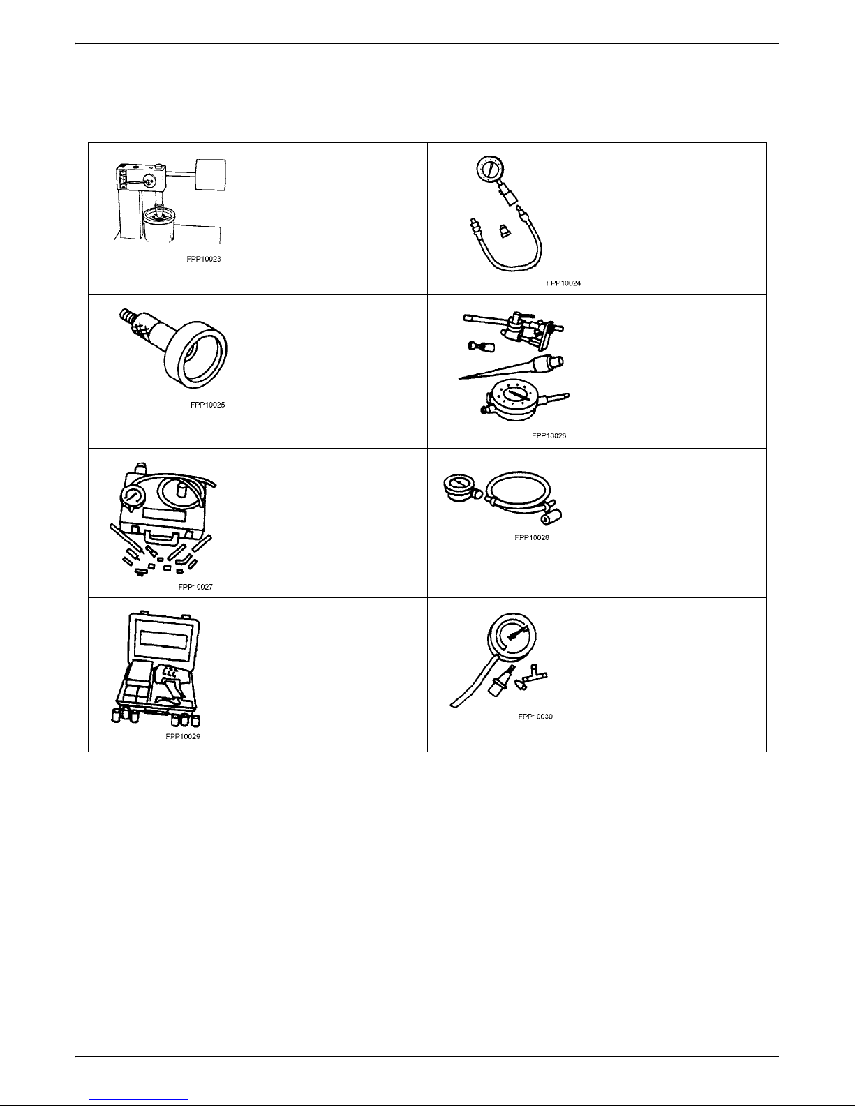
Special Tools
DSG-423 GENERAL INFORMATION
Commercially Available
Leakdown Tester
Cup Shaped Adapter
TOOL-6565-AB or Equivalent
Engine Cylinder Leak
Detection/Air Pressurization Kit
014-00705 or Equivalent
Compression Tester
014-00707 or Equivalent
Dial Indicator with Bracketry
TOOL-4201-C or Equivalent
Engine Oil Pressure Gauge
T73L-6600-A
12 Volt Master UV Diagnostic
Inspection Kit 164-R0756 or
Equivalent
Special Service Tools called for by the procedures can
be obtained by calling:
1-800-ROTUNDA (1-800-768-8632).
Vacuum/Pressure Tester 164R0253 or Equivalent
01-6

DSG-423 GENERAL INFORMATION
Inspection and Verification
1. Verify the customer concern by operating the engine
to duplicate the condition.
2. Visually inspect for obvious signs of mechanical and
electrical damage:
• Engine coolant leaks.
• Engine oil leaks.
• Fuel leaks.
• Damaged or severely worn pads.
• Loose mounting bolts, studs, and nuts.
3. If the inspection reveals obvious concerns that can
be readily identified, repair as required.
4. If the concerns remain after the inspection,
determine the symptoms and go to the symptom
chart.
Symptom Chart
Condition Possible Source Action
Difficult Starting Damaged starting system. Refer to Section 07.
Damaged charging system/battery. Refer to Section 06.
Burnt valve. Replace valve.
Worn piston. Replace piston and pin.
Worn piston rings or worn cylinder. Repair or replace cylinder blocks.
Damaged cylinder head gasket. Replace cylinder head gasket.
Damaged fuel system. Refer to Section 04.
Damaged ignition system. Refer to Section 03.
Spark plugs gapped incorrectly. Check plug gap.
Damaged hydraulic tappet or hydraulic lash adjuster. Replace tappet or lash adjuster.
Poor Idling Damaged hydraulic lash adjuster or hydraulic lash
Abnormal combustion Damaged hydraulic lash adjuster or hydraulic lash
adjuster.
Damaged hydraulic lash adjuster guide or hydraulic lash
adjuster.
Improper valve-to-valve seat contact. Replace valve or valve seat.
Damaged cylinder head gasket. Replace cylinder head gasket.
Malfunctioning or damaged fuel system. Refer to Section 04 of this manual*.
Malfunctioning or damaged ignition system. Refer to Section 03 of this manual*.
Spark plugs gapped incorrectly. Check plug gap.
Malfunctioning or damaged IAC motor or system. Refer to Section 03 of this manual.
adjuster.
Replace hydraulic lash adjuster or hydraulic lash
adjuster.
Replace hydraulic lash adjuster guide or hydraulic lash
adjuster.
Replace hydraulic lash adjuster or hydraulic lash
adjuster
Damaged hydraulic lash adjuster guide or hydraulic lash
adjuster.
Burnt or sticking valve. Repair or replace valve.
Weak or broken valve spring Replace valve spring
Carbon accumulation in combustion chamber. Eliminate carbon buildup.
Malfunctioning or damaged fuel system Refer to Section 04 of this manual*.
Malfunctioning or damaged ignition system. Refer to Section 03 of this manual*.
01-7
Replace hydraulic lash adjuster guide or hydraulic lash
adjuster.
DSG-423 GENERAL INFORMATION
Condition Possible Source Action
Excessive Oil
Consumption
Worn piston ring groove. Replace piston and pin.
Sticking piston rings. Repair or replace piston rings.
Worn piston or cylinders. Repair or replace piston or cylinder blocks.
Worn valve stem seal. Replace valve stem seal.
Worn valve stem or valve guide. Replace valve stem and guide.
Leaking oil. Repair oil leakage.
Worn piston rings. Replace piston rings.
Plugged PCV system. Service PCV system.
01-8

DSG-423 GENERAL INFORMATION
Condition Possible Source Action
Engine Noise Excessive main bearing oil clearance. Adjust clearance or replace main bearing.
Seized or heat damaged main bearing. Replace main bearing.
Excessive crankshaft end play. Replace crankshaft thrust main bearing.
Excessive connecting rod bearing oil clearance. Replace connecting rod.
Heat damaged connecting rod bearing. Replace connecting rod bearing.
Damaged connecting rod bushing. Replace connecting rod bushing.
Worn cylinder. Repair or replace cylinder blocks.
Worn piston or piston pin. Replace piston or piston pin.
Damaged piston rings. Replace piston rings.
Bent connecting rod. Replace connecting rod.
Malfunctioning hydraulic lash adjuster or hydraulic lash
adjuster.
Excessive hydraulic lash adjuster or hydraulic lash
adjuster clearance.
Broken valve spring. Replace valve spring.
Excessive valve guide clearance. Repair clearance or replace valve guide/stem.
Malfunctioning or damaged cooling system. Refer to Section 05.
Malfunctioning or damaged fuel system. Refer to Section 04.
Leaking exhaust system. Repair exhaust leakage.
Improper drive belt tension. Refer to Section 05.
Malfunctioning generator bearing. Refer to Section 06 for diagnosis and testing of the
Loose timing chain/belt. Adjust or replace timing chain/belt.
Damaged timing belt tensioner. Replace timing belt tensioner.
Malfunctioning water pump bearing. Replace water pump.
Insufficient Power Malfunctioning hydraulic lash adjuster or hydraulic lash
adjuster.
Damaged hydraulic lash adjuster guide or hydraulic lash
adjuster.
Replace hydraulic lash adjuster or hydraulic lash
adjuster.
Adjust clearance or replace hydraulic lash adjuster
guide or hydraulic lash adjuster.
generator.
Replace hydraulic lash adjuster or hydraulic lash
adjuster.
Replace hydraulic lash adjuster guide or hydraulic lash
adjuster.
Compression leakage at valve seat. Repair or replace valve, valve seat or cylinder head.
Seized valve stem. Replace valve stem.
Weak or broken valve spring. Replace valve spring.
Damaged cylinder head gasket. Replace cylinder head gasket.
Cracked or distorted cylinder head. Replace cylinder head.
Damaged, worn or sticking piston ring(s). Repair or replace piston ring(s).
Worn or damaged piston. Replace piston.
Malfunctioning or damaged fuel system. Refer to Section 04.
Malfunctioning or damaged ignition system. Refer to Section 03.
Damaged or plugged exhaust system. Repair or replace exhaust system.
01-9
DSG-423 GENERAL INFORMATION
PCV System Malfunction
A malfunctioning Positive Crankcase Ventilation
System (closed type) may be indicated by loping or
rough engine idle. Do not attempt to compensate for this
idle condition by disconnecting the PCV system and
making an air bypass or idle speed adjustment.
CAUTION: The removal of the PCV system from the
engine will adversely affect fuel economy and
engine crankcase ventilation with resultant
shortening of engine life.
Engine Oil Leaks
NOTE: When diagnosing engine oil leaks, the source
and location of the leak must be positively identified
prior to service.
Prior to performing this procedure, clean the cylinder
block, cylinder heads, valve covers, oil pan and flywheel
with a suitable solvent to remove all traces of oil.
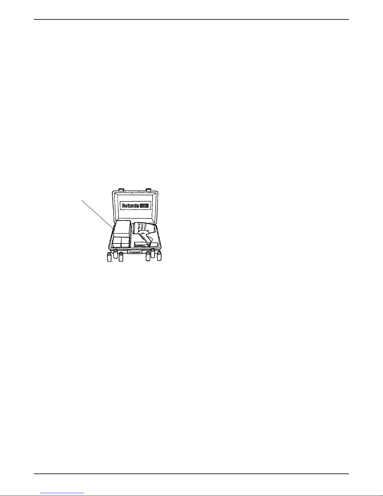
Oil Leak
Detector
Y112-R0021
Pressure Method
The crankcase can be pressurized to locate oil leaks.
The following materials are required to fabricate the tool
to be used:
• air supply and air hose
• air pressure gauge that registers pressure in 4 kPa
(1 psi) increments
• air line shutoff valve
• appropriate fittings to attach the above parts to oil fill,
PCV grommet hole and crankcase ventilation tube
• appropriate plugs to seal any openings leading to
the crankcase
• a solution of liquid detergent and water to be applied
with a suitable applicator such as a squirt bottle or
brush
Fabricate the air supply hose to include the air line
shutoff valve and the appropriate adapter to permit the
air to enter the engine through the crankcase ventilation
tube. Fabricate the air pressure gauge to a suitable
adapter for installation on the engine at the oil filler
opening.
CAUTION: Use extreme caution when pressurizing
crankcase. Applying air pressure above specified
pressure risks damage to seals, gaskets and core
plugs. Under no circumstances should pressure be
allowed to exceed 27 kPa (4 psi)
Fluorescent Oil Additive Method
Use a 12 Volt Master UV Diagnostic Inspection Kit, such
as the Rotunda Oil Leak Detector Y112-R0021 or
equivalent, to perform the following procedure for oil
leak diagnosis.
1. Clean the engine with a suitable solvent to remove
all traces of oil.
2. Drain engine oil crankcase and refill with
recommended oil, premixed with Diesel Engine Oil
Dye 164-R3705 meeting Ford specification ESEM9C103-B1 or equivalent. Use a minimum 14.8 ml
(0.5 ounce) to a maximum 29.6 ml (1 ounce) of
fluorescent additive to all engines. If the oil is not
premixed, fluorescent additive must first be added to
crankcase.
3. Run the engine for 15 minutes. Stop the engine and
inspect all seal and gasket areas for leaks using the
12 Volt Master UV diagnostic Inspection Kit. A clear
bright yellow or orange area will identify the leak. For
extremely small leaks, several hours may be
required for the leak to appear.
4. If necessary, pressurize the main oil gallery system
to locate leaks due to improperly sealed, loose or
cocked plugs.
5. Repair all leaks as required.
Testing Procedure
• Open the air supply valve until the pressure gauge
maintains 20 kPa (3 psi).
• Inspect sealed or gasketed areas for leaks by
applying a solution of liquid detergent and water over
areas for formation of bubbles which indicates
leakage.
Leakage Points - Above Engine
Examine the following areas for oil leakage.
• valve cover gaskets
• intake manifold gaskets
• cylinder head gaskets
• oil filter
• oil pump (if external)
• oil level indicator tube connection
• oil pressure sensor
Leakage Points - Under Engine
• oil pan gaskets
• oil pan sealer
• oil pan rear seal
• engine front cover gasket
01-10

DSG-423 GENERAL INFORMATION
• crankshaft front seal
• crankshaft rear oil seal
Leakage Points - with Flywheel Removed
NOTE: Air leakage in the area around a crankshaft rear
oil seal does not necessarily indicate a crankshaft rear
oil seal leak. However, if no other cause can be found
for oil leakage, assume that the crankshaft rear oil seal
is the cause of the oil leak.
NOTE: Light foaming equally around valve cover bolts
and crankshaft seals is not detrimental; no repairs are
required.
• rear main bearing cap and seals
• flywheel mounting bolt holes (with flywheel installed)
• camshaft rear bearing covers or pipe plugs at the
end of oil passages (except for overhead cam)
Oil leaks at crimped seams in sheet metal parts and
cracks in cast or stamped parts can be detected when
pressurizing the crankcase.
01-11
DSG-423 GENERAL INFORMATION
Compression Tests
Compression Gauge Check
1. Make sure the oil in the crankcase is of the correct
viscosity and at the proper level and that the battery
is properly charged. Operate until the engine is at
normal operating temperature. Turn the ignition
switch to the OFF position, then remove all the spark
plugs.
2. Set the throttle plates in the wide-open position.
3. Install a Compression Tester such as Rotunda
Compression Tester 059-R0009, or equivalent, in
the No. 1 cylinder.
4. Install an auxiliary starter switch in the starting
circuit. With the ignition switch in the OFF position,
and using the auxiliary starter switch, crank the
engine a minimum of five compression strokes and
record the highest reading. Note the approximate
number of compression strokes required to obtain
the highest reading.
5. Repeat the test on each cylinder, cranking the
engine approximately the same number of
compression strokes.
Test Results
The indicated compression pressures are considered
within specification if the lowest reading cylinder is
within 75 percent of the highest reading. Refer to the
Compression Pressure Limit Chart.
If one or more cylinders reads low, squirt approximately
one tablespoon of clean engine oil meeting Ford
specification ESE-M2C153-E on top of the pistons in
the low-reading cylinders. Repeat the compression
pressure check on these cylinders.
Compression Pressure Limit Chart
MAX-MIN
kPa (psi)
924 - 696
(134 - 101)
938 - 703
(136 - 102)
952 - 717
(138 - 104)
965 - 724
(140 - 106)
979 - 738
(142 - 107)
933 - 745
(144 - 109)
1007 - 758
(146 - 110)
1020 - 765
(148 - 111)
1034 - 779
(150 - 113)
1048 - 786
(152 - 114)
1062 - 793
(154 - 115)
1076 - 807
(156 - 117)
1089 - 814
(158 - 118)
1103 - 872
(160 - 120)
MAX-MIN
kPa (psi)
1131 - 848
(164 - 123)
1145 - 855
(166 - 124)
1158 - 869
(168 - 126)
1172 - 876
(170 - 127)
1186 - 889
(172 - 129)
1200 - 903
(174 - 131)
1214 - 910
(176 - 132)
1227 - 917
(178 - 133)
1241 - 931
(180 - 135)
1225 - 936
(182 - 136)
1269 - 952
(184 - 138)
1282 - 965
(186 - 140)
1296 - 972
(188 - 141)
1310 - 979
(190 - 142)
MAX-MIN
kPa (psi)
1338 - 1000
(194 - 146)
1351 - 1014
(196 - 147)
1365 - 1020
(198 - 148)
1379 - 1034
(200 - 150)
1303 - 1041
(202 - 151)
1407 - 1055
(204 - 153)
1420 - 1062
(206 - 154)
1434 - 1075
(208 - 156)
1448 - 1083
(210 - 157)
1462 - 1089
(212 - 158)
1476 - 1103
(214 - 160)
1489 - 1117
(216 - 162)
1503 - 1124
(218 - 163)
1517 - 1138
(220 - 165)
MAX-MIN
kPa (psi)
1154 - 1158
(224 - 168)
1558 - 1165
(226 - 169)
1572 - 1179
(228 - 171)
1586 - 1186
(230 - 172)
1600 - 1200
(232 - 174)
1055 - 1207
(153 - 175)
1627 - 1220
(154 - 177)
1641 - 1227
(238 - 178)
1655 - 1241
(240 - 180)
1669 - 1248
(242 - 181)
1682 - 1262
(244 - 183)
1696 - 1269
(246 - 184)
1710 - 1202
(248 - 186)
1724 - 1289
(250 - 187)
Example Readings
If, after checking the compression pressures in all
cylinders, it was found that the highest reading obtained
was 1351 kPa (196 psi), and the lowest pressure
reading was 1069 kPa (155 psi), the engine is within
specification and the compression is considered
satisfactory.
1110 - 834
(161 - 121)
1324 - 993
(192 - 144)
1631 - 1145
(222 - 166)
Interpreting Compression Readings
1. If compression improves considerably, with the
addition of oil, piston rings are faulty.
2. If compression does not improve with oil, valves are
sticking or seating improperly.
3. If two adjacent cylinders indicate low compression
pressures and squirting oil on each piston does not
increase compression, the head gasket may be
leaking between cylinders. Engine oil or coolant in
cylinders could result from this condition.
Use the Compression Pressure Limit Chart when
checking cylinder compression so that the lowest
reading is within 75 percent of the highest reading.
01-12
DSG-423 GENERAL INFORMATION
Cylinder Leakage Detection
When a cylinder produces a low reading, use of the
Engine Cylinder Leak Detection/Air Pressurization Kit,
such as the Rotunda Pressurization Kit 014-00705, or
equivalent, will be helpful in pinpointing the exact cause.
Rotunda Pressurization
Kit 014-00705
The leakage detector is inserted in the spark plug hole,
the piston is brought up to dead center on the
compression stroke, and compressed air is admitted.
Once the combustion chamber is pressurized, a special
gauge included in the kit will read the percentage of
leakage. Leakage exceeding 20 percent is excessive.
While the air pressure is retained in the cylinder, listen
for the hiss of escaping air. A leak at the intake valve will
be heard in the throttle body. A leak at the exhaust valve
can be heard at the tail pipe. Leakage past the piston
rings will be audible at the positive crankcase ventilation
(PCV) connection. If air is passing through a blown
head gasket to an adjacent cylinder, the noise will be
evident at the spark plug hole of the cylinder into which
the air is leaking. Cracks in the cylinder blocks or gasket
leakage into the cooling system may be detected by a
stream of bubbles in the radiator.
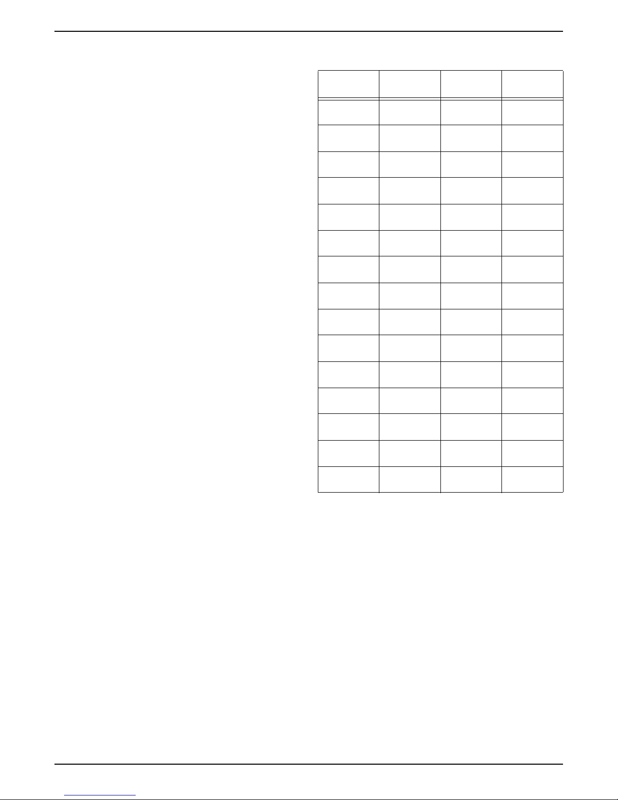
Intake Manifold Vacuum Test
Bring the engine to normal operating temperature.
Connect a Vacuum/Pressure Tester, such as Rotunda
Vacuum/Pressure Tester 059-00008 or equivalent, to
the intake manifold. Run the engine at the specified idle
speed.
Vacuum Pressure
Tester
059-00008
The vacuum gauge should read between 51-74 kPa
(15-22 in-Hg) depending upon the engine condition and
the altitude at which the test is performed. Subtract 5.5
kPa (1 in-Hg) from the specified reading for every 500
meters (1,000 feet) of elevation above sea level.
The reading should be quite steady. If necessary, adjust
the gauge damper control (where used) if the needle is
fluttering rapidly. Adjust the damper until the needle
moves easily without excessive flutter.
Oil Leak and Valve Stem Seal Test
The cylinder leakage detector tests for engine oil leaks
and checks the valve stem seals for leakage.
1. Plug all crankcase openings except the one used for
connecting the leakage detector.
2. Connect the Engine Cylinder Leak Detection/Air
Pressurization Kit to a crankcase opening (an oil
level indicator tube is convenient). Adjust the air
pressure to approximately 34 kPa (5 psi).
3. Using a solution of liquid soap and water, brush the
solution along the gasket sealing surfaces and
bearing seals. Look for bubbles or foam.
4. Remove the spark plugs and rotate the crankshaft
slowly with a wrench. Check for large amounts of air
escaping into the cylinders as each intake valve and
exhaust valve opens.
5. The spark plugs on the leaking cylinders will
probably show deposits of burned oil.
01-13
DSG-423 GENERAL INFORMATION
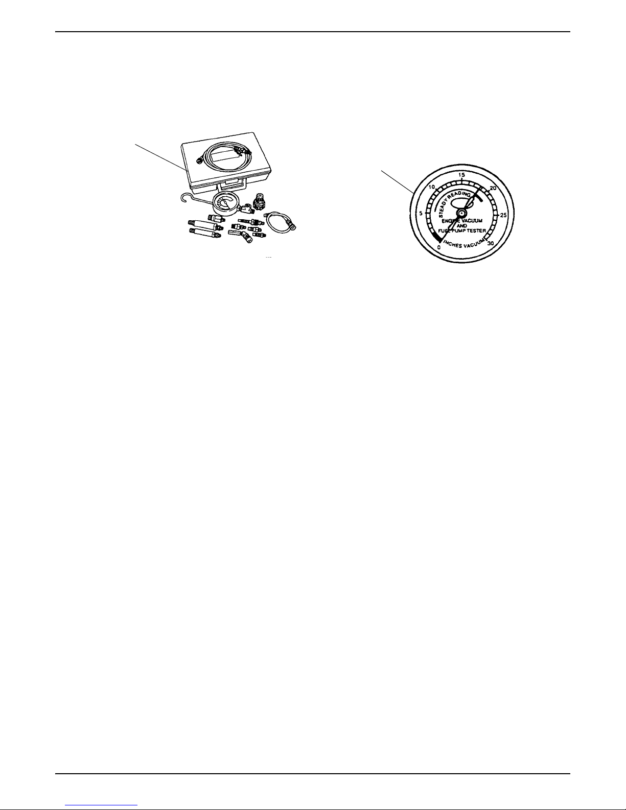
Interpreting Vacuum Gauge Readings
A careful study of the vacuum gauge reading while the
engine is idling will help pinpoint trouble areas. Always
conduct other appropriate tests before arriving at a final
diagnostic decision. Vacuum gauge readings, although
helpful, must be interpreted carefully.
Most vacuum gauges have a normal band indicated on
the gauge face.
The following are potential gauge readings. Some are
normal; others should be investigated further.
1. NORMAL READING: Needle between 51-74 kPa
(15-22 in-Hg) and holding steady.
2. NORMAL READING DURING RAPID
ACCELERATION AND DEACCELERATION: When
the engine is rapidly accelerated (dotted needle), the
needle will drop to a low reading (not to zero). When
the throttle is suddenly released, the needle will
snap back up to a higher than normal figure.
3. NORMAL FOR HIGH-LIFT CAMSHAFT WITH
LARGE OVERLAP: The needle will register as low
as 51 kPa (15 in-Hg) but will be relatively steady.
Some oscillation is normal.
4. WORN RINGS OR DILUTED OIL: When the engine
is accelerated (dotted needle), the needle drops to 0
kPa (0 in-Hg). Upon deceleration, the needle runs
slightly above 74 kPa (22 in-Hg).
5. STICKING VALVES: When the needle (dotted)
remains steady at a normal vacuum but occasionally
flicks (sharp, fast movement) down and back about
13 kPa (4 in-Hg), one or more valves may be
sticking.
6. BURNED OR WARPED VALVES: A regular, evenlyspaced, downscale flicking of the needle indicates
one or more burned or warped valves. Insufficient
hydraulic lash adjuster or hydraulic lash adjuster
(HLA) clearance will also cause this reaction.
7. POOR VALVE SEATING: A small but regular
downscale flicking can mean one or more valves are
not seating.
8. WORN VALVE GUIDES: When the needle oscillates
(swings back and forth) over about a 13 kPa (4 inHg) range at idle speed, the valve guides could be
worn. As engine speed increases, the needle will
become steady if guides are responsible.
9. WEAK VALVE SPRINGS: When the needle
oscillation becomes more violent as engine rpm is
increased, weak valve springs are indicated. The
reading at idle could be relatively steady.
10.LATE VALVE TIMING: A steady but low reading
could be caused by late valve timing.
11.IGNITION TIMING RETARDING: Retarded ignition
timing will produce a steady but somewhat low
reading.
12.INSUFFICIENT SPARK PLUG GAP: When spark
plugs are gapped too close, a regular, small
pulsation of the needle can occur.
13.INTAKE LEAK: A low, steady reading can be caused
by an intake manifold or throttle body gasket leak.
14.BLOWN HEAD GASKET: A regular drop of approx.
33-50 kPa (10-15 in-Hg) can be caused by a blown
head gasket or warped cylinder head-to-cylinder
block surface.
15.RESTRICTED EXHAUST SYSTEM: When the
engine is first started and is idled, the reading may
be normal, but as the engine rpm is increased, the
back pressure caused by a clogged muffler, kinked
tail pipe or other concerns will cause the needle to
slowly drop to 0 kPa (0 in-Hg). The needle then may
slowly rise. Excessive exhaust clogging will cause
the needle to drop to a low point even if the engine
is only idling.
When vacuum leaks are indicated, search out and
correct the cause. Excess air leaking into the system
will upset the fuel mixture and cause concerns such as
rough idle, missing on acceleration or burned valves. If
the leak exists in an accessory unit such as the power
brake booster, the unit will not function correctly. Always
fix vacuum leaks.
01-14

DSG-423 GENERAL INFORMATION
Excessive Engine Oil Consumption
The amount of oil an engine uses will vary with the way
the equipment is driven in addition to normal engine-toengine variation. This is especially true during the first
340 hours or 16,100 km (10,000 miles) when a new
engine is being broken in or until certain internal engine
components become conditioned. Engines used in
heavy-duty operation may use more oil. The following
are examples of heavy-duty operation:
• severe loading applications
• sustained high speed operation
Engines need oil to lubricate the following internal
components:
• cylinder block, cylinder walls
• pistons, piston pins and rings
• intake and exhaust valve stems
• intake and exhaust valve guides
• all internal engine components
When the pistons move downward, a thin film of oil is
left on the cylinder walls. As the engine is operated,
some oil is also drawn into the combustion chambers
past the intake and exhaust valve stem seals and
burned.
The following is a partial list of conditions that can affect
oil consumption rates:
• engine size
• operator driving habits
• ambient temperature
• quality and viscosity of the oil
Operating under varying conditions can frequently be
misleading. An engine that has been run for short hours
or in below-freezing ambient temperatures may have
consumed a “normal” amount of oil.
However, when checking engine oil level, it may
measure up to the full mark on the oil level dipstick due
to dilution (condensation and fuel) in the engine
crankcase. The engine might then be run at high
speeds where the condensation and fuel boil off. The
next time the engine oil is checked, it may appear that a
liter (quart) of oil was used in about 3 to 3-1/2 hours.
This perceived 3 to 3-1/2 hours per liter (quart) oil
consumption rate causes customer concern even
though the actual overall oil consumption rate is about
50 hours per liter (quart).
Make sure the selected engine oil meets Ford
specification WSS-M2C153-F and the recommended
API performance category “SJ” or higher and SAE
viscosity grade as shown in the equipment Owner’s or
Operators Engine handbook. It is also important that the
engine oil is changed at the intervals specified. Refer to
the Engine Operator’s handbook.
Oil Consumption Test
The following diagnostic procedure is used to determine
the source of excessive internal oil consumption.
NOTE: Oil use is normally greater during the first 300
hours of service. As hours increase, oil use generally
decreases. Engines in normal service should get at
least 31.7 hours per quart (900 miles per quart) after
300 hours of service. High speeds, heavy loads, high
ambient temperature and other factors may result in
greater oil use.
1. Determine customer’s engine load habits, such as
sustained high speed operation, extended idle,
heavy work loads and other considerations.
2. Verify that the engine has no external oil leak as
described under Engine Oil Leaks in the Diagnosis
and Testing portion of this section.
3. Verify that the engine has the correct oil level
dipstick.
4. Verify that the engine is not being run in an overfilled
condition. Check the oil level at least five minutes
after a hot shutdown with the engine/vehicle parked
on a level surface. In no case should the level be
above the top of the cross-hatched area and the
letter F in FULL. If significantly overfilled, perform
steps 5 through 9. If not proceed to step 10.
5. Drain the engine oil, remove and replace the oil filter
and refill with one quart less than the recommended
amount.
6. Run the engine for three minutes (10 minutes if
cold), and allow the oil to drain back for at least five
minutes with the engine/vehicle on a level surface.
7. Remove oil level dipstick and wipe clean.
CAUTION: Do not wipe with anything contaminated
with silicone compounds.
8. Reinstall the oil level dipstick, being sure to seat it
firmly in the oil level indicator tube. Remove the oil
level dipstick and draw a mark on the back
(unmarked) surface at the indicated oil level. This
level should be about the same as the ADD mark on
the face of the oil level dipstick.
9. Add one quart of oil. Restart the engine and allow to
idle for at least two minutes. Shut off the engine and
allow the oil to drain back for at least five minutes.
Mark the oil level dipstick, using the procedure
above. This level may range from slightly below the
top of the cross-hatched area to slightly below the
letter F in FULL.
10.Record the vehicle mileage or hours.
01-15

DSG-423 GENERAL INFORMATION
11.Instruct the customer to run engine as usual and
perform the following:
• Check the oil level regularly at intervals of
3 to 3-1/2 hours.
• Return to the service point when the oil level
drops below the lower (ADD) mark on the oil level
dipstick.
• Add only full quarts of the same oil in an emer-
gency. Note the mileage at which the oil is added.
12.Check the oil level under the same conditions and at
the same location as in Steps 7-9.
• Measure the distance from the oil level to the UP-
PER mark on the oil level dipstick and record.
• Measure the distance between the two scribe
marks and record.
• Divide the first measurement by the second.
• Divide the hours run during the oil test by the re-
sult. This quantity is the approximate oil consumption rate in hours per quart.
13.If the oil consumption rate is unacceptable, proceed
to next step.
14.Check the positive crankcase ventilation (PCV)
system. Make sure the system is not plugged.
15.Check for plugged oil drain-back holes in the
cylinder heads and cylinder blocks.
16.If the condition still exists after performing the above
steps, proceed to next step.
17.Perform a cylinder compression test -- Refer
to“Compression Tests” on page 12 or perform a
cylinder leak detection test with Engine Cylinder
Leak Detection/Air Pressurization Kit -- Refer
to“Cylinder Leakage Detection” on page 13. This
can help determine the source of oil consumption
such as valves, piston rings or other areas.
NOTE: After determining if worn parts should be
replaced, make sure correct replacement parts are
used.
18.Check valve guides for excessive guide clearances.
REPLACE all valve stem seals after verifying valve
guide clearance.
19.Worn or damaged internal engine components can
cause excessive oil consumption. Small deposits of
oil on the tips of spark plugs can be a clue to internal
oil consumption. If internal oil consumption still
persists, proceed as follows:
• Remove the engine from the vehicle and place it
on an engine work stand. Remove the intake
manifolds, cylinder heads, oil pan and oil pump.
• Check piston ring clearance, ring gap and ring
orientation. Repair as required.
• Check for excessive bearing clearance. Repair
as required.
20.Perform the oil consumption test to confirm the oil
consumption concern has been resolved.
Oil Pressure Test
1. Disconnect and remove the oil pressure sensor from
the engine.
2. Connect the Engine Oil Pressure Gauge and
Transmission Test Adapter to the oil pressure
sender oil gallery port.
3. Run the engine until normal operating temperature is
reached.
4. Run the engine at 3000 rpm and record the gauge
reading.
5. The oil pressure should be within specifications.
6. If the pressure is not within specification, check the
following possible sources:
• insufficient oil
• oil leakage
• worn or damaged oil pump
• oil pump screen cover and tube
• excessive main bearing clearance
• excessive connecting rod bearing clearance
01-16

DSG-423 GENERAL INFORMATION
Valve Train Analysis – Static
With engine off and valve cover removed, check for
damaged or severely worn parts and correct assembly.
Make sure correct parts are used with the static engine
analysis as follows.
Rocker Arm
• Check for loose mounting bolts, studs and nuts.
• Check for plugged oil feed in the rocker arms or
cylinder head.
Camshaft Roller Followers and Hydraulic Lash
Adjusters
• Check for loose mounting bolts on camshaft carriers.
• Check for plugged oil feed in the camshaft roller
followers, hydraulic lash adjusters (HLA) or cylinder
heads.
Camshaft
• Check for broken or damaged parts.
• Check the bolts on the intake manifold.
Push Rods (if equipped)
• Check for bent push rods and restricted oil passage.
Valve Springs
• Check for broken or damaged parts.
Valve Spring Retainer and Valve Spring Retainer
Keys
• Check for proper seating of the valve spring retainer
key on the valve stem and in valve spring retainer.
Valve Spring Retainer Keys
• Check for proper seating on the valve stem.
Valve Train Analysis – Dynamic
Start the engine and, while idling, check for proper
operation of all parts. Check the following:
Rocker Arm
• Check for plugged oil in the rocker arms or cylinder
head.
• Check for proper overhead valve train lubrication.
If insufficient oiling is suspected, accelerate the engine
to 1200 rpm ± 100 rpm with the PTO in NEUTRAL or
load removed and the engine at normal operating
temperature. Oil should spurt from the rocker arm oil
holes such that valve tips and rocker arms are well oiled
or, with the valve covers off, oil splash may overshoot
the rocker arms. If oiling is insufficient for this to occur,
check oil passages for blockage.
Push Rods (if equipped)
• Check for bent push rods and restriction in oil
passage.
Positive Rotator and Valve Spring Retainer Keys
• Check for proper operation of positive rotator.
Valves and Cylinder Head
• Check for plugged oil drain back holes.
• Check for missing or damaged valve stem seals or
guide mounted valve stem seals.
If insufficient oiling is suspected, check oil passages for
blockage, then accelerate the engine to 1200 rpm with
the PTO in NEUTRAL or load removed and the engine
at normal operating temperature. Oil should spurt from
the rocker arm oil holes such that valve tips and
camshaft roller followers are well oiled. With the valve
covers off, some oil splash may overshoot camshaft
roller followers.
Valves and Cylinder Head
• Check the head gasket for proper installation.
• Check for plugged oil drain back holes.
• Check for worn or damaged valve tips.
• Check for missing or damaged guide-mounted valve
stem seal.
• Check collapsed lash adjuster gap.
• Check installed valve spring height.
• Check for missing or worn valve spring seats.
• Check for plugged oil metering orifice in cylinder
head oil reservoir (if equipped).
Static checks (engine off) are to be made on the engine
prior to the dynamic procedure.
01-17
DSG-423 GENERAL INFORMATION
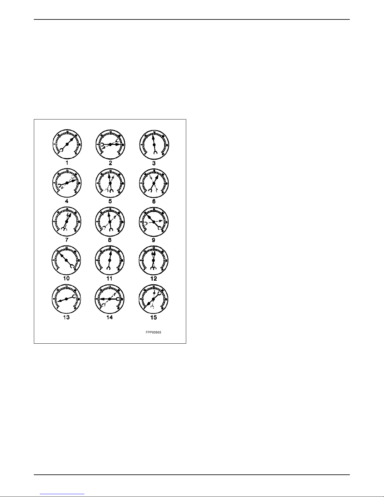
Camshaft Lobe Lift
Check the lift of each lobe in consecutive order and
make a note of the readings.
1. Remove the valve covers.
2. Remove the rocker arm seat bolts, rocker arm seat
and rocker arms (if equipped).
Dial
Indicator
Cup Shaped
Adapter
Typical Engine with Push Rods
3. Make sure the lash adjuster is seated against
camshaft. Install the dial Indicator with Bracketry so
the ball socket adapter of the indicator is on top of
the hydraulic lash adjuster or the Cup Shaped
Adapter is on top of the push rod and in the same
plane as the lash adjuster push rod movement.
4. On engines with overhead cam, install the dial
Indicator with Bracketry so the plunger is on top of
the camshaft lobe and in the same plane as the
camshaft lobe movement.
5. Remove the spark plugs.
6. Connect an auxiliary starter switch in the starting
circuit. Crank the engine with the ignition switch in
the OFF position. Bump the crankshaft over until the
indicator is measuring on the base circle of the
camshaft lobe (in its lowest position). If checking
during engine assembly, turn the crankshaft using a
socket or ratchet.
7. Zero the dial indicator. Continue to rotate the
crankshaft slowly until the camshaft lobe is in the
fully-raised position (highest indicator reading).
NOTE: If the lift on any lobe is below specified service
limits, the camshaft and any component operating on
worn lobes must be replaced.
01-18

DSG-423 GENERAL INFORMATION
8. Compare the total lift recorded on the dial indicator
with specifications.
9. To check the accuracy of the original dial indicator
reading, continue to rotate the crankshaft until the
indicator reads zero.
10.Remove the dial indicator, adapter and auxiliary
starter switch.
11.Reinstall components as necessary.
CAUTION: Do not rotate the crankshaft until lash
adjusters have had sufficient time to bleed down.
To do otherwise may cause serious valve damage.
Manually bleeding-down lash adjusters will reduce
waiting time.
01-19

DSG-423 GENERAL INFORMATION
Hydraulic Valve Lash Adjuster
Hydraulic lash adjuster noise can be caused by any of
the following:
• excessively collapsed lash adjuster gap
• sticking lash adjuster plunger
• lash adjuster check valve not functioning properly
• air in lubrication system
• leakdown rate too rapid
• excessive valve guide wear
Excessive collapsed lash adjuster gap can be caused
by loose rocker arm seat bolts/nuts, incorrect initial
adjustment or wear of lash adjuster face, or worn roller
lash adjusters, push rod, rocker arm, rocker arm seat or
valve tip. With lash adjuster collapsed, check gap
between the valve tip and the rocker arm to determine if
any other valve train parts are damaged, worn or out of
adjustment.
A sticking lash adjuster plunger can be caused by dirt,
chips or varnish inside the lash adjuster.
A lash adjuster check valve that is not functioning can
be caused by an obstruction such as dirt or chips that
prevent it from closing when the camshaft lobe is lifting
the lash adjuster. It may also be caused by a broken
check valve spring.
Air bubbles in the lubrication system will prevent the
lash adjuster from supporting the valve spring load. This
can be caused by too high or too low an oil level in the
oil pan or by air being drawn into the system through a
hole, crack or leaking gasket on the oil pump screen
cover and tube.
If the leakdown time is below the specified time for used
lash adjusters, noisy operation can result. If no other
cause for noisy lash adjusters can be found, the
leakdown rate should be checked and any lash
adjusters outside the specification should be replaced.
Assembled lash adjusters can be tested with Hydraulic
lash adjuster Leakdown Tester to check the leakdown
rate. The leakdown rate specification is the time in
seconds for the plunger to move a specified distance
while under a 22.7 kg (50 lb.) load. Test the lash
adjusters as follows:
Leakdown Testing
NOTE: Do not mix parts from different hydraulic lash
adjusters. Parts are select-fit and are not
interchangeable.
1. Clean the lash adjuster to remove all traces of
engine oil.
NOTE: Lash adjusters cannot be checked with engine
oil in them. Use only testing fluid. New hydraulic lash
adjusters are already filled with testing fluid.
2. Place the lash adjuster in the tester with the plunger
facing upward. Position the steel ball provided in the
plunger cap. Add testing fluid to cover the hydraulic
lash adjuster and compress Leakdown Tester until
the hydraulic lash adjuster is filled with testing fluid
and all traces of air bubbles have disappeared. The
fluid can be purchased from the tester’s
manufacturer. Using kerosene or any other fluid will
not provide an accurate test.
Steel Ball
Leakdown
Tester
Lash Adjuster
3. Adjust the length of the ram so the pointer is just
below the start timing mark when the ram contacts
the hydraulic lash adjuster. Start Timing as the
pointer passes the start timing mark and end timing
as the pointer reaches the center mark.
Center
Mark
Start
Timing
Mark
Pointer
4. A satisfactory lash adjuster must have a leakdown
rate (time in seconds) within specified minimum and
maximum limits.
5. If the lash adjuster is not within specification, replace
it with a new lash adjuster. Do not disassemble and
clean new lash adjusters before testing because oil
contained in the new lash adjuster is test fluid.
6. Remove the fluid from the cup and bleed the fluid
from the lash adjuster by working the plunger up and
down. This step will aid in depressing the lash
adjuster plungers when checking valve clearance.
Ram
01-20
DSG-423 GENERAL INFORMATION
GENERAL SERVICE PROCEDURES
WARNING: TO AVOID THE POSSIBILITY OF
PERSONAL INJURY OR DAMAGE TO THE
EQUIPMENT, DO NOT OPERATE THE ENGINE
UNTIL THE FAN BLADE HAS BEEN EXAMINED FOR
POSSIBLE CRACKS AND SEPARATION.
NOTE: Illustrations are typical and may not reflect your
particular engine. Specifications show the expected
minimum or maximum condition.
NOTE: If a component fails to meet the specifications, it
is necessary to replace or refinish. If the component can
be refinished, wear limits are provided as an aid to
making a decision. Any component that fails to meet
specifications and cannot be refinished must be
replaced.
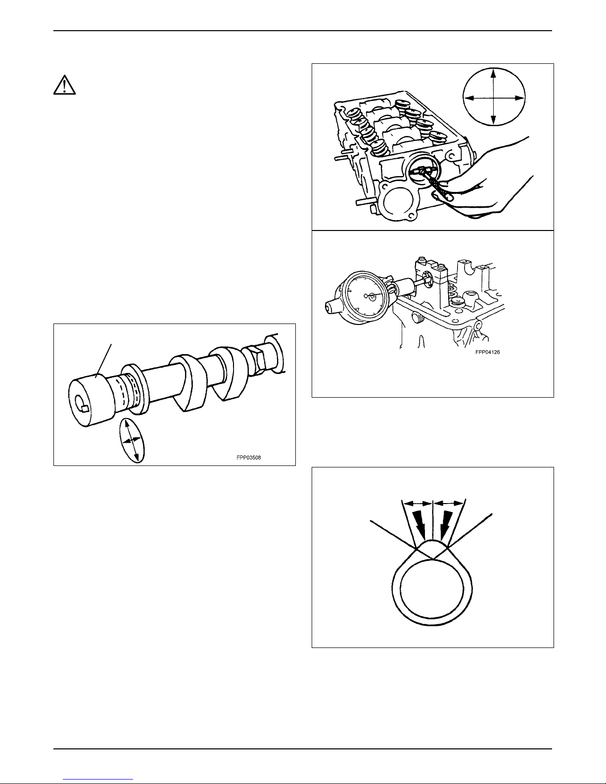
Camshaft Journal Diameter
• Measure each camshaft journal diameter in two
directions.
• If it is out of specification, replace as necessary.
Journal
Camshaft Journal Clearance
NOTE: The camshaft journals must meet specifications
before checking camshaft journal clearance.
• Measure each camshaft bearing in two directions.
• Subtract the camshaft journal diameter from the
camshaft bearing diameter
Camshaft Lobe Surface
• Inspect camshaft lobes for pitting or damage in the
active area. Minor pitting is acceptable outside the
active area
.
Active Area
01-21
DSG-423 GENERAL INFORMATION
Camshaft Lobe Lift
Special Tool(s)
Dial Indicator with Bracketry
TOOL-4201-C or Equivalent
Special Service Tools called for
by the procedures can be
obtained by calling:
1-800-ROTUNDA
(1-800-768-8632)
1. Use the Dial Indicator with Bracketry to measure
camshaft intake lobe lift.
Camshaft Runout
Special Tool(s)
Dial Indicator with Bracketry
TOOL-4201-C or Equivalent
Special Service Tools called for
by the procedures can be
obtained by calling:
1-800-ROTUNDA
(1-800-768-8632)
NOTE: Camshaft journals must be within specifications
before checking runout.
• Use the Dial Indicator with Bracketry to measure the
camshaft runout.
• Rotate the camshaft and subtract the lowest dial
indicator reading from the highest dial indicator
reading.
2. Rotate the camshaft and subtract the lowest dial
indicator reading from the highest dial indicator
reading to figure the camshaft lobe lift.
3. Use the Dial Indicator with Bracketry to measure
camshaft exhaust lobe lift.
4. Rotate the camshaft and subtract the lowest dial
indicator reading from the highest dial indicator
reading to figure the camshaft lobe lift.
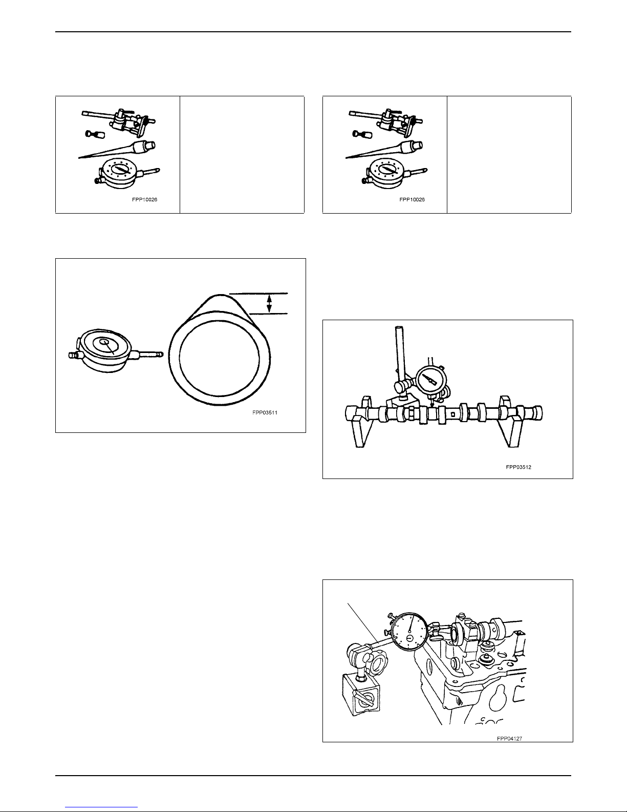
Camshaft End Play
• Move camshaft to the rear.
• Zero dial indicator.
• Move camshaft to the front.
• Compare end play with specifications.
Dial Indicator
01-22
DSG-423 GENERAL INFORMATION
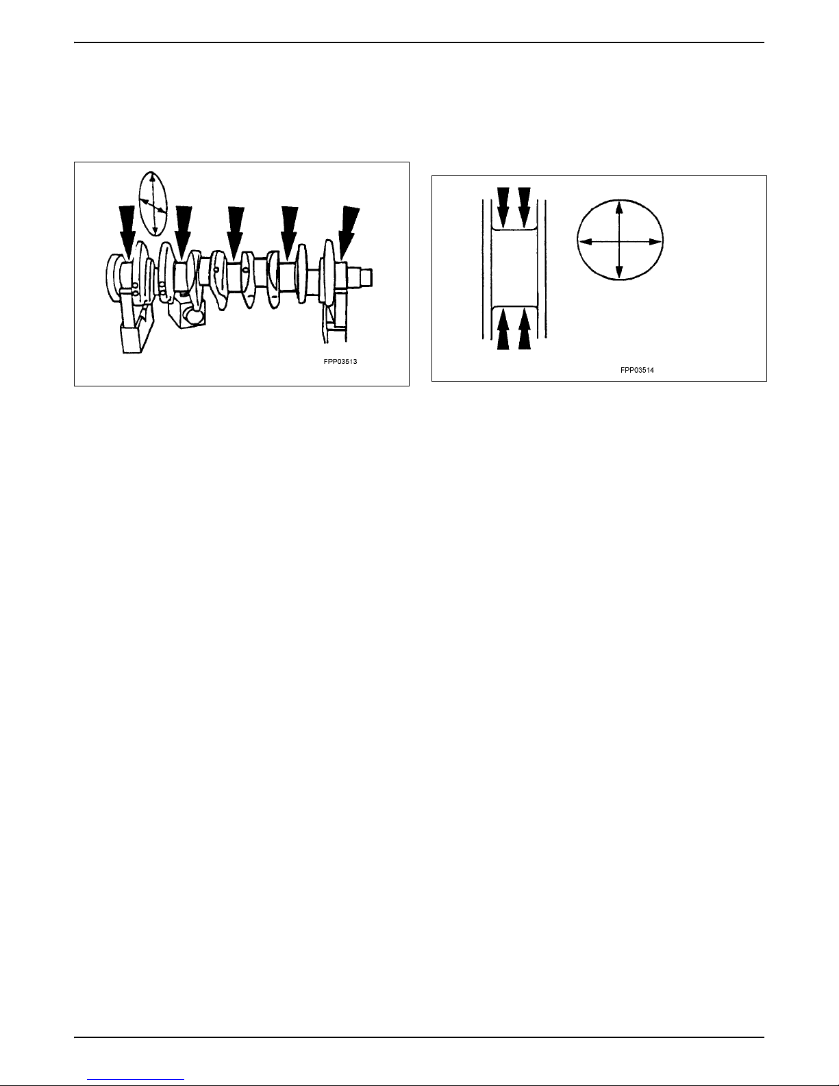
Crankshaft Main Bearing Journal Diameter
• Measure each of the crankshaft main bearing journal
diameters in at least two directions.
• If it is out of specification, replace as necessary.
Crankshaft Main Bearing Journal Taper
• Measure each of the crankshaft main bearing journal
diameters in at least two directions at each end of
the main bearing journal.
• If it is out of specifications, replace as necessary.
01-23
DSG-423 GENERAL INFORMATION
Crankshaft Main Bearing Journal
Clearance
Special Tool(s)
Plastigage®
D81L-6002-B or Equivalent
Special Service Tools called for
by the procedures can be
obtained by calling:
1-800-ROTUNDA
(1-800-768-8632)
NOTE: Crankshaft main bearing journals must be within
specifications before checking journal clearance.
1. Remove the crankshaft main bearing caps and
bearings.
2. Lay a piece of Plastigage® across the face of each
crankshaft main surface.
4. Verify the crankshaft journal clearance.
• If it is out of specification, replace as necessary
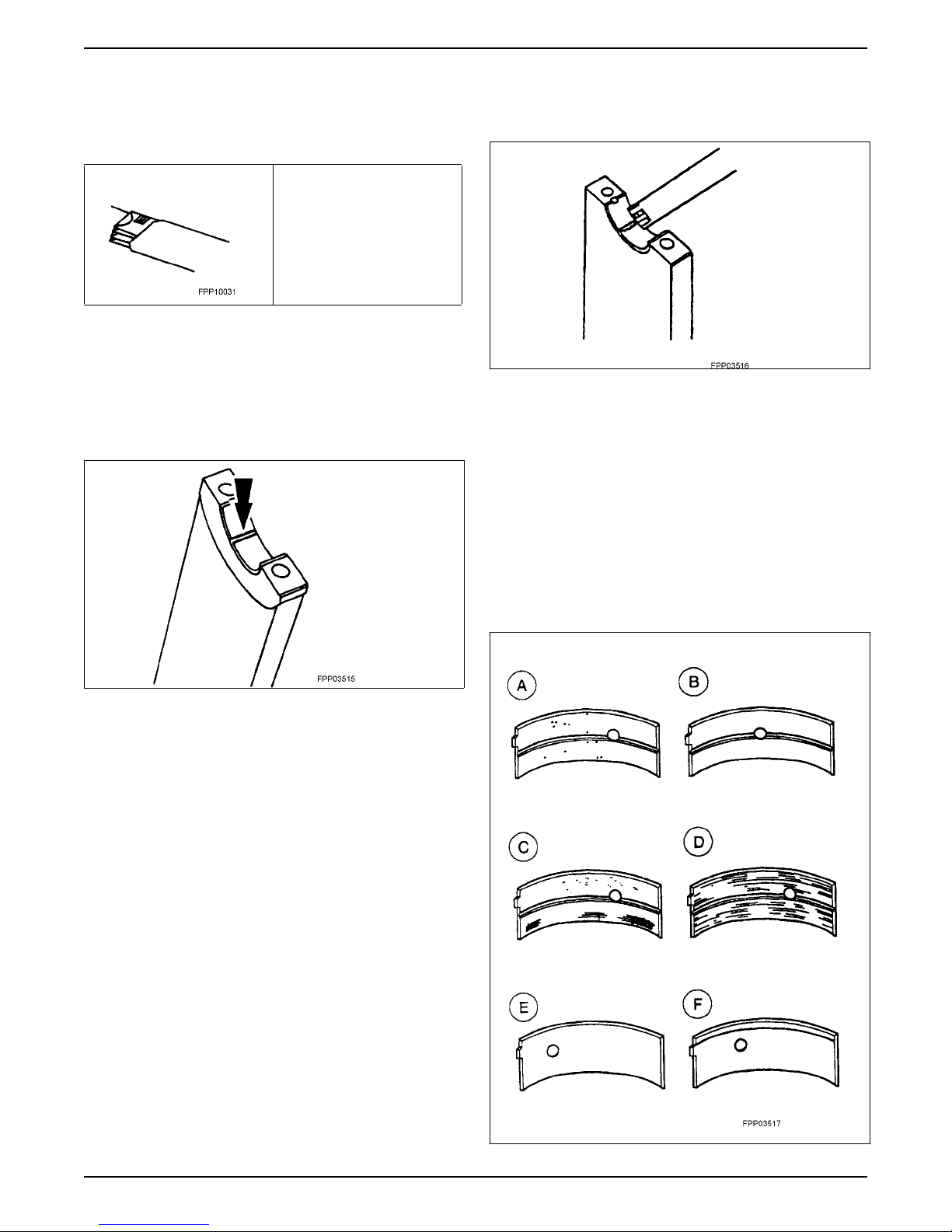
Bearing Inspection
Inspect bearings for the following defects. Possible
causes are shown:
• Cratering – fatigue failure (A)
• Spot polishing – improper seating (B)
• Scratching – dirty (C)
• Base exposed – poor lubrication (D)
• Both edges worn – journal damaged (E)
• One edge worn – journal tapered or bearing not
seated (F)
NOTE: Do not turn the crankshaft while doing this
procedure.
3. Install and remove the crankshaft main bearing cap.
01-24
DSG-423 GENERAL INFORMATION
Crankshaft End Play
Special Tool(s)
Dial Indicator with Bracketry
TOOL-4201-C or Equivalent
Special Service Tools called for
by the procedures can be
obtained by calling:
1-800-ROTUNDA
(1-800-768-8632)
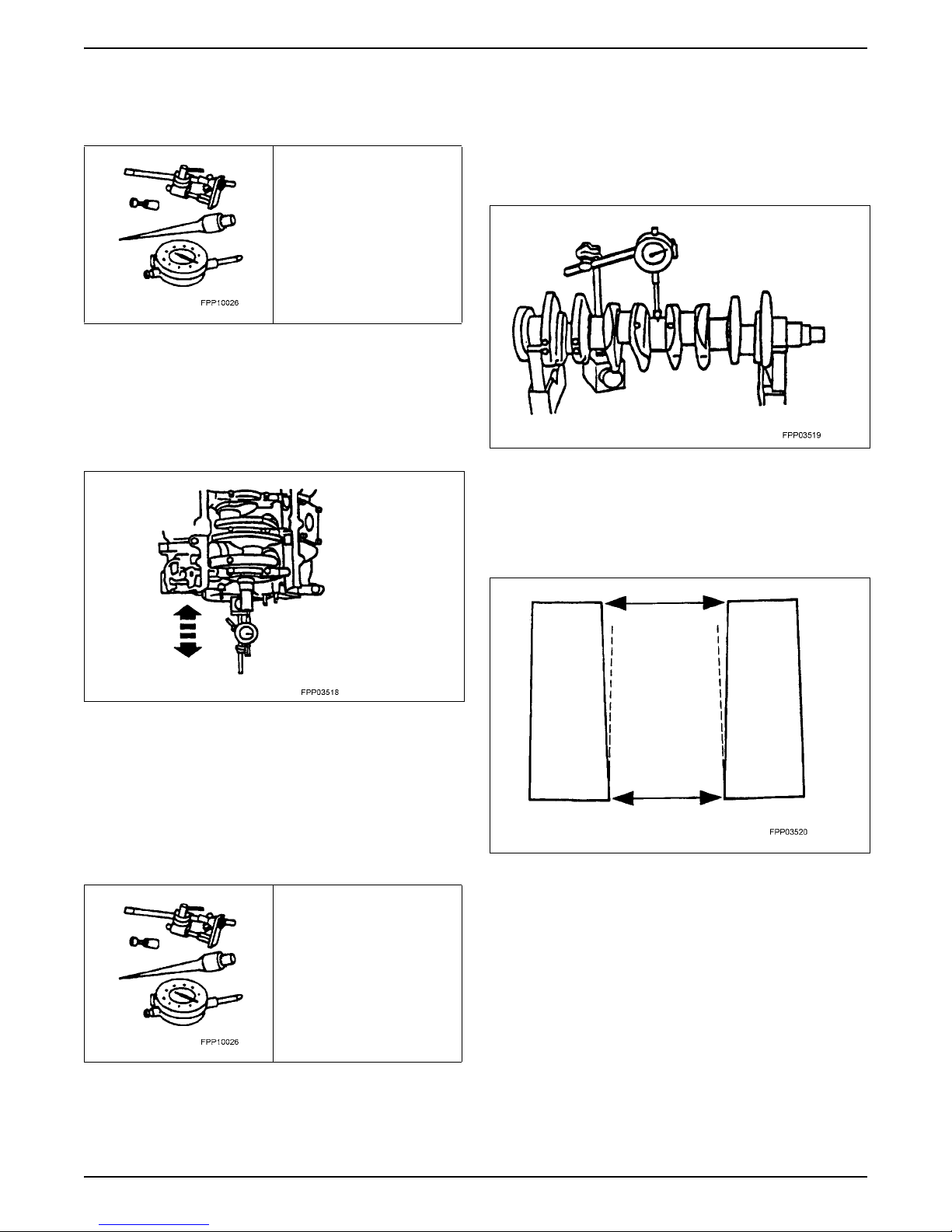
1. Measure the crankshaft end play. Use the Dial
Indicator with Bracketry to measure crankshaft end
play.
2. Position the crankshaft to the rear of the cylinder
block.
3. Zero the Dial Indicator with Bracketry.
Use the Dial Indicator with Bracketry to measure the
crankshaft runout.
• Rotate the crankshaft and subtract the lowest dial
indicator reading from the highest dial indicator
reading to figure the crankshaft runout. If it is out of
specification, replace as necessary.
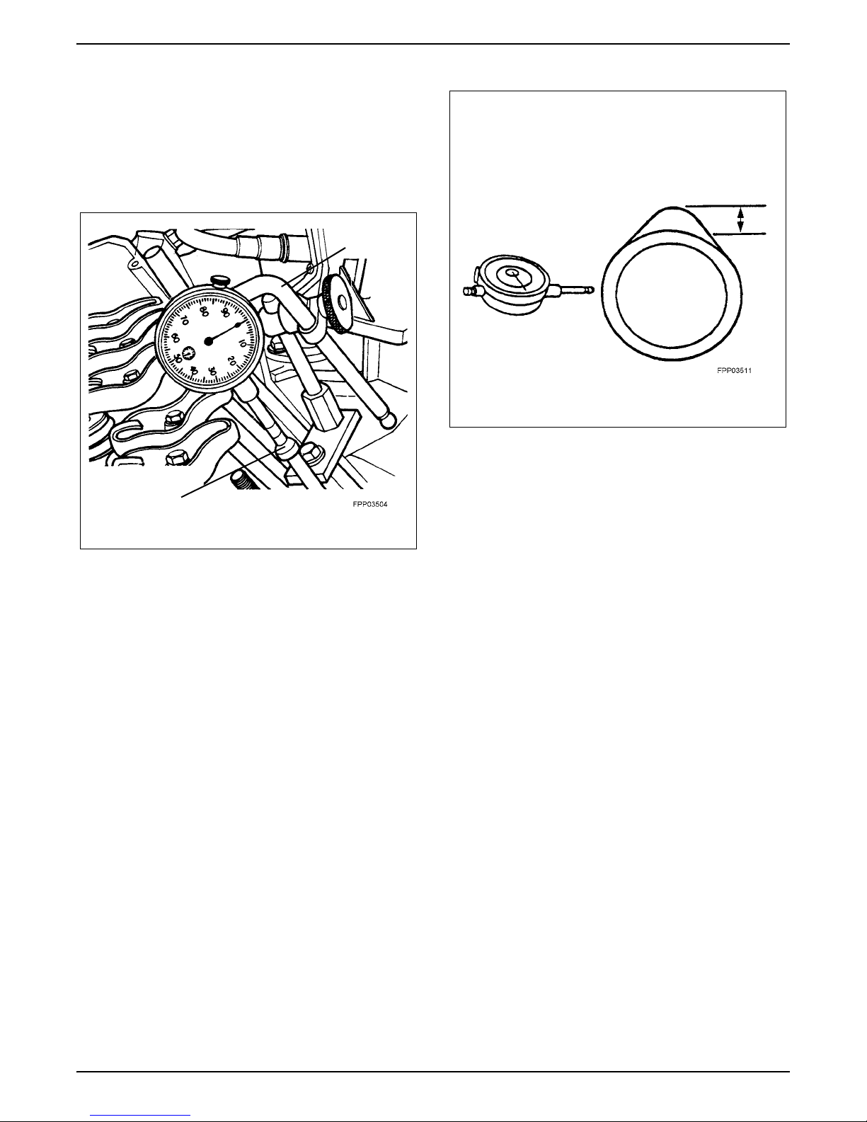
Cylinder Bore Taper
Measure the cylinder bore at the top and bottom. Verify
the cylinder bore is within the wear limit. The difference
indicates the cylinder bore taper. Bore the cylinder to
the next oversize.
4. Move the crankshaft to the front of the cylinder block.
Note and record the camshaft end play.
• If camshaft end play exceeds specifications, re-
place the crankshaft thrust washers or thrust
bearing.
Crankshaft Runout
Special Tool(s)
Dial Indicator with Bracketry
TOOL-4201-C or Equivalent
Special Service Tools called for
by the procedures can be
obtained by calling:
1-800-ROTUNDA
(1-800-768-8632)
NOTE: Crankshaft main bearing journals must be within
specifications before checking runout.
01-25
DSG-423 GENERAL INFORMATION
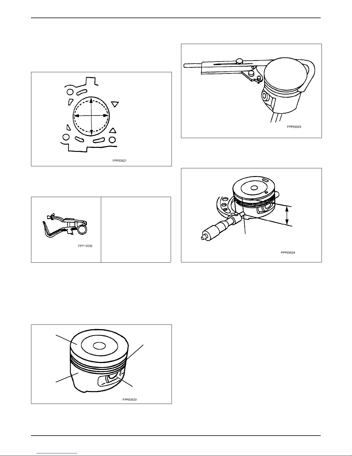
Cylinder Bore Out-of-Round
Measure the cylinder bore in two directions. The
difference is the out-of-round. Verify the out-of-round is
within the wear limit and bore the cylinder to the next
oversize limit.
Piston Inspection
Special Tool(s)
• Make sure the oil ring holes are clean.
Piston Diameter
• Measure the piston skirt diameter.
Piston Ring Groove Cleaner
D81L-6002-D or Equivalent
Special Service Tools called for
by the procedures can be
obtained by calling:
1-800-ROTUNDA
(1-800-768-8632)
CAUTION: Do not use a caustic cleaning solution or
a wire brush to clean the pistons or possible damage can occur.
1. Clean and inspect the ring lands, skirts, pin bosses,
and the tops of the pistons. If wear marks or
polishing is found on the piston skirt, check for a bent
or twisted connecting rod.
Top of Piston
Ring Lands
Piston to Cylinder Bore Clearance
Subtract the piston diameter from the cylinder bore
diameter to find the piston-to-cylinder bore clearance.
Skirts
2. Use the Piston Ring Groove Cleaner to clean the
piston ring grooves.
Pin Bosses
01-26
DSG-423 GENERAL INFORMATION
Piston Selection
NOTE: The cylinder bore must be within the
specifications for taper and out-of-round before fitting a
piston.
1. Select a piston size based on the cylinder bore.
NOTE: For precision fit, new pistons are divided into
three categories within each size range based on their
relative position within the range. A paint spot on the
new pistons indicates the position within the size range.
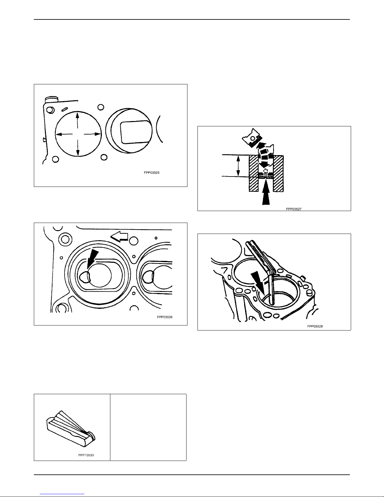
CAUTION: Use care when fitting piston rings to
avoid possible damage to the piston ring or the cylinder bore.
CAUTION: Piston rings should not be transferred
from one piston to another to prevent damage to
cylinder worn or piston.
NOTE: Cylinder bore must be within specification for
taper and out-of-round to fit piston rings.
1. Use a piston without rings to push a piston ring in a
cylinder to the bottom of ring travel.
2. Use a feeler gauge to measure the top piston ring
end gap and the second piston ring end gap.
2. Choose the piston with the proper paint color.
• Red – in the lower third of the size range.
• Blue – in the middle third of the size range.
• Yellow – in the upper third of the size range.
Piston Ring End Gap
Special Tool(s)
Feeler Gauge
D81L-4201-A or Equivalent
Special Service Tools called for
by the procedures can be
obtained by calling:
1-800-ROTUNDA
(1-800-768-8632)
01-27
 Loading...