

Page 1

OPERATION AND MAINTENANCE MANUAL
Backpressure Monitor & Logger
Revision: 7.0 June 2011 Part Number: M18-0017
Page 2

Table of Contents
Symbols used in this Manual ..................................................................................................... 3
Introduction ................................................................................................................................ 4
Parts List .................................................................................................................................... 5
Understanding the BPM Connections ........................................................................................ 6
Understanding the Remote Driver Display ................................................................................ 7
Installation Procedure ................................................................................................................ 8
Using the DPF Utilities Software .............................................................................................. 14
Maintenance............................................................................................................................. 17
BPM Troubleshooting Guide .................................................................................................... 18
2
Page 3
Symbols Used in this Manual
This symbol emphasizes non-compliance with instructions or procedures can re-
WARNING
CAUTION
sult in serious injuries or death to personnel.
This symbol emphasizes non-compliance with instructions or procedures may
cause damage to equipment.
ATTENTION
TECH TIP
This symbol highlights and draws specific attention to important information
This symbol indicates that in this situation, the technician would suggest this
course of action to be done.
3
Page 4

Introduction
A diesel particulate filter (DPF) is used to reduce the exhaust particulate matter emitted by an engine. By
definition, the DPF accumulates the particulate matter (soot) and oxidizes it with a passive, active, or combined
strategy.
Diesel engines are sensitive to backpressure created by any restriction in the exhaust flow. When a DPF
is used, the backpressure varies depending on the soot loading in the filter. The filter will fill up with soot and ash
over time and periodically require cleaning. As a result, a backpressure monitor is used to inform the vehicle operator that the filter needs cleaning.
Monitoring exhaust backpressure is also a useful way to identify the condition of the engine. Increased
soot levels from the engine will cause the filter to load faster. Identifying this trend allows the service technician
to correct engine problems before they become severe. Backpressure monitoring can also indicate DPF overloading and/or slow soot combustion.
Engine Control Systems is pleased to offer a DPF Backpressure Monitor & Logger with features to protect both your engine and your DPF. The Backpressure Monitor & Logger will be referred to as the BPM throughout this manual.
4
Please completely read this manual.
ATTENTION
Page 5

Parts List
The following parts are included in the BPM kit. Please take time to read all installation instructions and setup procedure carefully to ensure proper installation and use of the provided software. Spare parts for older BPM models are
listed at the bottom of this page.
Backpressure Monitor & Logger Part List
(Complete kit - A56-0067)
PART # DESCRIPTION QTY
A56-0066 Backpressure Monitor - Watlow thermocouple & Deutsch connector 1
J35-0269 Remote Driver Display 1
C25-0232 Condensation Trap 1
J16-0021 Fitting – ¼ NPT male - ¼ hose barb 1
J16-0126 Clear plastic tube — 10 ft 1
J16-0313 ¼“ swage to ¼“ swage brass 1
J16-0314 ¼” swage to ¼” NPT brass 2
J16-0316 Synflex tube - 1/4” OD, 6 ft 1
J16-0322 Brass tube insert 2
J19-0161 Stainless steel backpressure tube—1/4” OD 1
J35-0333 Watlow K-Type Thermocouple 1
J35-0334 K-Type thermocouple extension wire 1
J16-0340 Coupling—M14 x 1.5 1
J35-0270 Power cable — 20 ft 1
J35-0271 Remote Driver display cable—20 ft 1
J35-0272 Data cable—3 ft 1
J35-0277 2 amp fuse 1
J35-0278 Fuse holder 1
J16-0005 Coupling-NPT-SS 1/4 - 3/4” OD 1
M18-0017 Backpressure Monitor & Logger Installation & Setup Manual 1
M16-0019 Utility CD 1
M18-0026 BPM Driver’s Display Visor Card 1
Optional Accessories
J35-0273 Remote Driver Display Extension cable—20 ft. 1
J35-0336 Remote Driver Display Extension cable—40 ft. 1
Spare Parts for Old Style BPM with Omega thermocouple
A56-0063 Backpressure Monitor - Omega thermocouple & yellow connector 1
J35-0275 Omega Thermoco uple — 6” K-type 1
J35-0226 Thermocouple wire—15 ft 1
J35-0276 Thermocouple wire strain relief - #PCLM-SMP 1
J16-0285 Thermocouple plug — male 1
J16-0315 1/8” swage to ¼” NPT brass 1
If you are missing any components, contact your ECS representative before continuing
the installation.
ATTENTION
5
Page 6
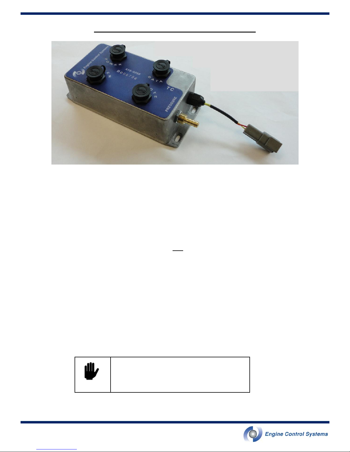
Understanding the BPM Connections
Figure 1 - Backpressure Monitor & logger (BPM)
POWER
Connects to continuous vehicle battery power. The BPM will operate with a 12V or 24V power source.
DATA
Connects to the PC for setup and data downloading.
REGEN
Connects to the junction box on Purifilter Plus systems only. The BPM can monitor the regeneration status when
connected.
REMOTE
Connects to the Remote Driver Display.
TC
Connects to the K-Type thermocouple that measures the exhaust temperature.
PRESSURE
Connects to the pressure line that samples the exhaust stream backpressure
Use caution when plugging in the cables. Make sure
the pins are aligned properly before pushing in the
connector.
CAUTION
6
Page 7

Understanding the Remote Driver Display
Figure 2 - Remote Driver Display
Pink light - SYSTEM ERROR
This pink light flashes when there is a BPM system error. It has two modes of operation: flashing and off.
FLASHING
soon as possible. If the error light stays on in combination with the red alarm light, the BPM and DPF should be
inspected as soon as possible. Refer to the troubleshooting guide for error light causes and m ore information.
OFF:
: A flashing error light indicates that there is a system error and the BPM should be inspected as
The unit is working properly.
Red light - SERVICE DPF NOW
This red light indicates that very high exhaust backpressure exists and the DPF is in need of immediate attention. There are two modes of operation: ON (solidly illuminated) and off.
ON
: When the light is illuminated for longer than 45 seconds, the operator should service the DPF within 24hrs.
If the red light is on in combination with the system error light, the vehicle should be parked in a safe location
immediately. If when parked, the red light and pink light remain on with the vehicle at idle and/or with engine
turned off, do not continue to operate the vehicle. Engine damage may result. Product warranty may be void.
Refer to the troubleshooting guide for more information.
OFF:
The unit is working properly.
Yellow light - SCHEDULE DPF SERVICE
This yellow light indicates that higher than normal exhaust backpressure exists and that there is a need to
schedule the DPF for service. The light has two modes of operation: ON (solidly illuminated) and off.
ON
: It is normal that this light may briefly illuminate when pulling heavy loads up grades. When the light illuminates for periods longer than 45 seconds
should schedule the DPF for service. Delays in servicing may raise the alarm level to “SERVICE DPF NOW”.
Refer to the troubleshooting guide for more information.
OFF:
The DPF is not in need of service
Green light - POWER
This green light indicates that the system is powered and is operational. There are two modes of operation for
this light: ON and OFF.
ON:
When the light is illuminated the system is powered properly. This light remains illuminated even when the
engine is shut off.
OFF
: The system is either not powered or there is a problem with the system. Refer to the troubleshooting guide
for more information..
while the vehicle is in normal use on a level roadway, the operator
7
Page 8

Installation Procedure
Tools and Accessories Required
Power drill with 3/8” drill bit.
Self tapping 3/16” screws
Welding Tools for couplings
Zip ties for fastening cabling to the vehicle
Electrical Connectors
Laptop
Step 1 - Installing the thermocouple and stainless steel backpressure sampling tube
a. Drill two 3/8” holes in the exhaust pipe for the couplings. The couplings should be installed on a
straight section of pipe and not on bends or flex pipe. They should also be located upstream of the
DPF and as close as possible to the DPF inlet.
b. Find the 1/4” NPT coupling and the M14 coupling and weld to the exhaust pipe so that they align with
the drilled holes. The M14 coupling is the larger coupling. The NPT coupling should be upstream of the
M14 coupling.
c. Locate the thermocouple, apply anti-sieve to the threads, and tighten into the M14 coupling as shown
in Figure 3. Keep thermocouple wire away from hot surfaces.
d. Locate the 1/4” swage to 1/4” NPT brass fitting, apply anti-seize to the NPT threads, and tighten into
the NPT coupling.
e. Insert the stainless steel sampling tube into the 1/4” swage hole until it stops. Tighten the compression
nut finger tight and then turn one full turn further with a wrench. The backpressure sampling tube is
shown in Figure 4.
Figure 3 - Installation of the thermocouple sensor at the DPF inlet (pressure tube not installed
yet). Keep thermocouple wire away from hot
surfaces.
If the exhaust inlet diameter is less than 3 inches, an NPT coupling and a ther-
mocouple adaptor will be required to center the thermocouple tip within the
ATTENTION
8
pipe. Please call technical services.
Figure 4 - Installation of the backpressure
sampling tube
Page 9

Installation Procedure (cont’d)
Step 2 - Mounting the BPM
Mount the BPM in a location that is protected from direct water spray, excess heat, and moving parts. Some recommended locations include a battery box or engine compartment. Figure 5 shows recommended locations. If
the BPM cannot be installed in the recommended locations, cover the BPM with a shield or a box to protect it.
Ensure that the BPM is exposed to atmospheric pressure. The following page illustrates acce ptable orientations.
a
Figure 5 - Examples of properly mounted
BPMs; a) in an electrical panel; b) in the engine
compartment; c) in a battery box. BPM shown
may differ from the one supplied.
Do not install the BPM in direct exposure to water spray or rain. Do not
CAUTION
pressure wash the BPM.
Do not install the BPM inside the driver’s compartment. A leak could expose
the driver to exhaust gas.
CAUTION
If the BPM cannot be installed in the recommended locations, cover the BPM
b
c
with a shield or a box to protect it. Ensure that the BPM is exposed to atmos-
ATTENTION
pheric pressure.
The BPM will operate properly up to a maximum temperature of 70°C. Make
sure the BPM is installed in a location that does not exceed this temperature.
ATTENTION
9
Page 10

Installation Procedure (cont’d)
ACCEPTABLE BPM orientations:
a. Vertical surface with tube to the right
b. Vertical surface with tube to the left
c. Vertical surface with tube downward
d. Hanging from a horizontal surface with face downward (not
shown)
a
b
c
UNACCEPTABLE BPM orientations:
a. Vertical surface with tube upward
b. Sitting on a horizontal surface with the face upward
b
a
UNCCEPTABLE mounting locations or orientations will VOID the warranty!
ATTENTION
10
Page 11

Installation Procedure (cont’d)
Step 3 - Assemble the Condensation Trap
Locate the condensation trap, 1/4” NPT to 1/4” barbed fitting, and 1/4” swage to 1/4” NPT brass fitting.
a. Apply anti-seize compound to the NPT threads of each fitting
b. Remove the condensation trap from the box. Be careful not to lose the two small crews in the box that
fasten the bracket to the trap.
c. Thread the barbed fitting into the outlet
d. Thread the swage fitting into the inlet
Step 4 - Mount the Condensation Trap
Mount the condensation trap at a location higher than the exhaust system so that excess condensation drains to
the exhaust. The condensation trap should be installed below the BPM to prevent any moisture from entering the
BPM. Make sure it is away from all moving parts and excessive heat. The flow direction will be marked by an
arrow or small triangle pointing in the direction of flow. The exhaust sample should flow from the exhaust stream
towards the BPM.
a. Remove the condensation trap bracket from the box and use it to mark the holes
b. Drill two mounting holes on the vehicle for the bracket
c. Fasten the bracket to the condensation trap using the two screws provided. Make sure the outlet is
facing the correct direction.
d. Mount the condensation trap to the vehicle using the drilled holes.
e. Measure and cut the appropriate length of clear plastic tube
f. Push the clear plastic tube onto the barbed fittings at the condensation trap and BPM
marked with a square and tighten.
marked with a triangle and tighten.
Figure 6 - Two examples of condensation trap mounting.
The flow direction is marked on the condensation trap by an arrow or small triangle pointing in the
direction of flow. The exhaust sample should flow from the exhaust stream towards the BPM.
ATTENTION
11
Page 12

Installation Procedure (cont’d)
Step 5 - Assemble and route the Synflex backpressure sampling tube
a. Measure and cut the appropriate length of Synflex tube to go from the end of the stainless steel tube to
the condensation trap. Cut the ends square and clean to ensure proper sealing when assembled.
b. Locate the brass tube inserts and press into each end of the synflex tube
c. Locate the 1/4” swage to 1/4” swage fitting
d. Connect one end of the fitting to the stainless steel tube. Tighten compression nut finger tight and then
tighten one full turn with a wrench
e. Slide one end of the synflex tube into the fitting. Tighten compression nut finger tight and then tighten
one full turn with a wrench.
f. Route the synflex tube to the condensation trap and slide the tube into the inlet fitting. Tighten com-
pression nut finger tight and then tighten one full turn with a wrench.
Be careful not to lose the small brass tube inserts.
CAUTION
Step 6 - Route the thermocouple wire
a. Plug the thermocouple extension wire into the thermocouple and route to the BPM. Do not cut the ther-
mocouple extension wire. Plug the thermocouple extension into the BPM.
Do not cut or shorten the thermocouple extension wire.
ATTENTION
ATTENTION
Route wires with existing wire harnesses and keep away from hot surfaces. Wire
loom is recommended but not provided.
12
Page 13

Installation Procedure (cont’d)
Step 7 - Mount the Remote Driver Display
Mount the Remote Driver Display in clear view of the driver as shown in Figure 7. Do not interfere with any driving mechanisms, instruments, or gages. Plug the six pin Remote Driver Display cable into the Remote Driver
Display and route to the BPM. Plug the other end into the “Remote” plug on the BPM.
ARB Verification requires that
the Remote Driver Display is
visible when sitting in the
ATTENTION
driver’s seat.
Use caution when plugging in the cables. Make sure the pins are aligned
properly before pushing in the con-
CAUTION
nector.
Figure 7 - Remote Driver Display mounted to instrument panel
Step 8 - Install the Power Cable
The BPM must be connected to a continuous and unswitched power supply of 12V or 24V. It is strongly recommended to wire directly to ONE
a. Locate the power cable, measure, and cut to the desired length.
b. Strip the outer gray wire to expose 6” of the black and white wire.
c. Connect the provided the fuse holder to the WHITE (positive) wire. Do not insert the fuse yet.
d. Connect the red wire to the positive terminal of the battery
e. Connect the black wire to the negative terminal of the battery. Connect wires to a single battery.
f. Route the power cable to the BPM and plug it into the “Power” connector.
g. Insert the 2 amp fuse into the fuse holder.
battery.
ATTENTION
ATTENTION
In the event of jump starting the
vehicle, remove the BPM fuse.
Failure to do so could result in
BPM damage.
In the event of welding on the
vehicle, remove the BPM fuse.
Failure to do so could result in
BPM damage.
Figure 8 - Installing the power cable
TECH TIP
Connect the BPM directly to only
ONE
battery
13
Page 14

Using the DPF Utilities Software
STEP 1 - Install the DPF Utilities Software
The software required to view and retrieve data from the BPM is provided with your kit.
Computer Requirements
The software requires the minimum system requirements:
Windows XP/2000 System
Pentium 3 Class System or newer
At least 64 MB of RAM
RS-232 Serial port
Serial port to USB adaptor if no serial port is available
Software Installation
Insert the CD containing the ECS Backpressure Monitor & Logger Software into your computer’s CD-ROM drive.
Click install and follow the procedures on screen.
STEP 2: Making the Connection
a. Connect your computer to the BPM using the data cable provided.
b. Double click on the ECS_DPF_Utilites shortcut located on the desktop. This will launch the DPF Alarm
Logger Utilities window shown in Figure 9.
c. Enter the Comm port number and select “OK.”
Figure 9 - Select the Comm port that the data
cable is plugged in to.
TECH TIP
14
Comm port 1 will work for most users. However, if you are
using a USB to serial port adaptor, you may have to change
this number
Page 15

Using the DPF Utilities Software (cont’d)
STEP 3: Viewing Real-time data from the BPM
After clicking “OK,” the Parameter View tab will open as shown in Figure 10. From this tab, you can see real-time
data from the BPM. The flashing blue light next to the word “Update” indicates that the computer is connected to
the BPM. Check to make sure that the thermocouple reading is reasonable. For example, if the thermocouple is
exposed to room temperature, it will read around 20
o
C.
Figure 10 - “Parameter View” tab showing real-time data from the BPM.
TECH TIP
Ensure that you have a good connection by checking the temperature readings. For a cold engine, the thermocouple temperature should read ambient temperature. It is possible to
have a flashing blue light, but and bad connection. If you have
a thermocouple reading of 0.0, you are not connected properly. Try a different Comm port setting.
15
Page 16

Using the DPF Utilities Software (cont’d)
STEP 4: Accessing the data stored in the BPM
Selecting the “Log View” tab will bring up the data transfer area of the utilities program. This is shown in Figure
11. This is where all communications and information can be controlled by the user.
On the right hand side are buttons used for downloading and saving the data stored in the BPM. The “Parameter
Logs” contains the temperature, pressure, regeneration status, and alarm status taken every 12 seconds over
the past 24 hours. The “Histogram Logs” contain frequency data in the form of a histogram from the last 365
days.
Select the desired radio button and click on “Get data.” The data will show up in the white viewing pane on the
left.
When you have selected to read one type of data (Histogram or Parameters) you must clear the screen before
displaying the next time to ensure accurate data display. This can be done with the “Clear Log Display” button in
the upper right hand section of this tab.
Figure 11 - The Log View tab is where the data
transfer takes place.
STEP 5: Saving the BPM data
Once the desired data is shown in the viewing pane, it can be saved to your computer.
Clicking on the “Save for Excel” button will save the data in the viewing pane to a CSV file that can be opened by
most viewing programs.
It is recommended to save all data log files, both Parameter logs and both Histogram logs, at every de-ashing for
future reference. Each log must be brought into the viewing pane individually and saved individually.
TECH TIP
16
Include the date and vehicle information in the filename when saving
the data.
Page 17

Maintenance
Proper maintenance of the BPM system is important for reliable operation. Lack of BPM maintenance may void
DPF warranty. The following service items should be performed:
At every oil change
Empty any water that has collected in the condensation trap. To do this, twist off the metal bowl protec-
tor and remove the bowl. Empty water out of the bowl and reinstall.
Inspect the clear tube that goes from the condensation trap to the BPM. There should be no visible
soot. If there is soot, see troubleshooting guide for further instruction.
Inspect the pressure line going from the DPF to the condensation trap. Make sure that this line is clear.
To clean the line, remove line at the condensation trap and use compressed air to blow out the line.
Serve items as defined by the appropriate Purifilter or Purifilter Plus product manual.
At every Filter de-ashing
All the service items outlined to be performed at every oil change above
Service items as defined by appropriate Purifilter or Purifilter Plus manual
Engine-Out Opacity should be measured. If opacity indicates engine maintenance is required, this
maintenance should be performed prior to re-installation of the filter.
:
:
Download histogram data and parameter data from the BPM and save it. Refer to page 16 for
downloading and saving instructions.
17
Page 18

BPM Troubleshooting Guide
Note: Refer to Purifilter or Purifilter Plus Product Manuals for Additional Troubleshooting information
Event Probable Cause(s) Action
1 Yellow light illuminates continu-
ously for periods longer than 45
seconds in duration
2 Red light illuminates continu-
ously for periods longer than 45
seconds in duration OR red
light stays illuminated at all
times.
Engine exhaust backpressure is
increasing and the DPF should be
scheduled for service within the
next 72 hours.
Engine exhaust backpressure is at
a level where the DPF should be
cleaned within the next 24 hours.
Purifilter systems - download BPM histogram
and parameter files and confirm reported
Yellow Alarm
Confirm duty cycle is acceptable for pas-
sive regeneration.
Remove DPF and clean
Perform all service items defined in the
Maintenance section under this service
Purifilter Plus systems - perform on-board
regeneration.
Purifilter systems - download BPM histogram
and parameter files and confirm reported
Red Alarm
Confirm duty cycle is acceptable for pas-
sive regeneration
Remove DPF and clean
3 Pink system error light flashes
continuously
Backpressure Sensor problem
* The logged parameter data and
user interface will show “-3276.8” in
the pressure column when there is
an abnormal pressure condition.
Thermocouple connection problem
* The logged parameter data will
show “SAT” in the temperature
column and user interface when
the thermocouple is disconnected
High backpressure Error. Backpressure greater than 500 mbar.
This will latch the system error
light.
Perform all service items defined in the
Maintenance section under this service
If red light remains illuminated, contact
your ECS distributor to reset the red light
Purifilter Plus systems - perform on-board
regeneration.
Refer to Purifilter Plus manual if problem is
apparent.
Check the backpressure sensor line for any
breaks or leaks . Check the tubing between the
water trap and exhaust pipe for any blockage
and clear with compressed air blowing toward
the exhaust pipe. Service the condensation
trap and condensation trap filter.
Check thermocouple connections. Check
thermocouple sensor. Make sure the thermocouple polarity is correct. Refer to installation
instructions.
Follow the actions required in item 2 above.
Contact your ECS distributor to reset the
system error light.
4 All lights on the remote driver
display are on continuously
18
Internal problem with the BPM Contact your ECS distributor.
Power supply voltage has been
out of the normal operating range.
The BPM will operate with a supply voltage between 9V and 30V.
Disconnect power to the BPM for 20 seconds
and then reconnect power. This can be done
by removing the fuse or the power connector, whichever is more convenient.
Page 19

BPM Troubleshooting Guide (cont’d)
Event Probable Cause(s) Action
5
DPF requires more frequent
cleanings than usual
6 System Error Light flashes in
combination with Red and/or
Yellow alarm illumination when
vehicle is driven or at idle.
7
System Error Light flashes
shortly after engine shut down
8 When the engine is warming
up, the thermocouple temperature decreases.
Filter is not completely clean Clean filter again with reference to the ap-
plicable ECS product manual.
Engine requires servicing Measure the opacity of the engine out ex-
haust. If it is out of the manufacturers
specification, service engine immediately.
Severe system backpressure
due to engine malfunction or
failure to service filter.
Remove, inspect and clean the DPF on
appropriate cleaning machine. Perform
engine inspection and correct faults found.
Confirm engine opacity prior to reinstallation of cleaned filter. Service BPM
Logger condensation trap and clean sensor line. Contact your ECS distributor to
rest lights.
Engine shut down while excessively hot
The yellow and red wires are
crossed in the thermocouple
connector. This only applies to
the old (yellow) Omega thermo-
Start engine and operate. After two minutes
the System Error light should turn off. If this
error persists, contact your ECS distributor.
Check the connector and ensure that the
YELLOW is connected to the positive terminal and the RED is connected to the
negative terminal.
couple style.
9 Soot in the clear tube between
the condensation trap and the
BPM
10
Remote driver display shows no
lights
High backpressure occurred at
some point.
Download data from the BPM and check
for signs of high backpressure. Service
condensation trap. Clean DPF or regenerate as required.
No power getting to the remote
driver display
Check that power is getting to the Remote
Driver Display. Locate the “Remote” connection at the BPM. Pull out the connector
and check that 5 volts is available at the
center pin. If there is power, the Remote
Driver Display is faulty. If there is no
power, the remote driver display is not getting power from the BPM. See next item for
troubleshooting.
No power getting to the BPM. Inspect BPM fuse and connectors first. If
no troubles found, disconnect the power
connector at the BPM and check for power
from the battery. If there is vehicle battery
voltage, then the BPM could be faulty.
19
Page 20

Engine Control Systems Limited
World Headquarters
83 Commerce Valley Drive East
Thornhill, ON, L3T 7T3
Phone: 905-707-7746
Toll Free: 1-800-661-9963
Fax: 905-707-7686
Engine Control Systems Ltd.
North America—Western
4910 Longley Lane, Suite 103
Reno, Nevada, 89502
Phone: 1-775-827-3400
Fax: 1-775-827-1670
Engine Control Systems Europe AB
European Headquarters
Box 9015, Agnesfridsvagen, 184
SE-200 39 Malmo, Sweden
Phone: 46 (40) 670 1550
Fax: 46 (40) 210 335
Website: www.enginecontrolsystems.com
Email: ecs@enginecontrolsystems.com
Contact Information
20
 Loading...