

Page 1
User Manual
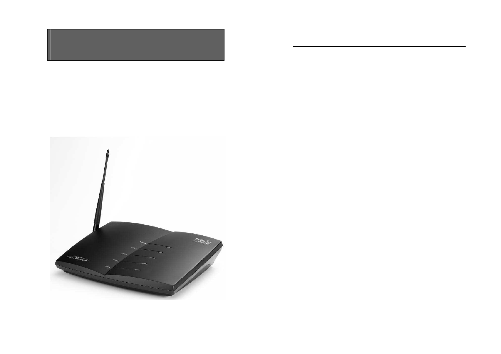
DuraFon PRO
Digital Long Range Cordless
System
2
User Manual
Table of Contents
SAFETY INSTRUCTIONS ............................................................. 3
G
ENERAL SAFETY INSTRUCTIONS
P
RODUCT SAFETY INSTRUCTIONS
REGULATORY INFORMATION .................................................... 6
EQUIPMENT CHECKLIST ........................................................... 11
BASE ILLUSTRATION ................................................................. 12
B
ASIC BASE STATION FEATURES
A
DDITIONAL BASE STATION FEATURES
GETTING STARTED ................................................................... 16
B
ASE STATION INSTALLATION
BASIC OPERATIONS ................................................................. 20
O
PERATION MODES
Base Operation Modes ....................................................... 20
TECHNICAL SPECIFICATIONS ..................................................... 21
.................................................................... 20
...................................................... 3
..................................................... 4
..................................................... 13
............................................. 15
......................................................... 16
Page 2

3
Safety Instructions
Caution
:
Your wireless telephone gives you freedom and flexibility to stay
4
in touch while you move around. However, when using your phone
equipment, safety instructions should be followed to avoid the risks of
fire, electric shock, injury to person, and damage to property.
General Safety Instructions
1. When using your wireless phone, ensure your safety and the safety
of others:
a. Always watch where you are walking and standing.
b. Don’t let a phone call distract you from working safely.
c. If power goes out, it won’t work. Recommend backup power.
2. In an emergency:
a. If an emergency occurs, dial the emergency phone number.
Remember: if you are in an area where your phone does not
have a clear signal from the base, it is highly probable that the
call may not go through. Locate the nearest landline telephone
or other communications device to call for help.
b. Emergency calls may not automatically provide emergency
personnel with your name, phone number or location.
3. Notice to Hearing Aid Users: This phone system is compatible with
inductively coupled hearing aids.
4. Notice to Cardiac Pacemaker Users: Preliminary studies done by the
US FDA and others have shown that, although interference to the
implanted cardiac pacemaker may occur when operating very
closely, wireless telephones “do not seem to pose a significant
problem for pacemaker wearers.” However, until more is known,
FDA suggests that people with pacemakers may want to take
precautions when using or carrying a wireless telephone to ensure
that there is ample distance between the telephone and the
pacemaker. Do not carry the handset in a breast pocket. If you have
any reason to suspect that interference is taking place, turn off your
handset immediately.
Product Safety Instructions
1. Read and understand all instructions.
2. Follow all warnings and instructions including those marked on the
product.
3. Changes or modifications to this product not expressively approved
by the manufacturer will void the warranty and the FCC
authorization to operate the equipment. Use only manufacturer
provided accessories.
4. Do not use the telephone near water. Never spill liquid of any kind
on this product.
5. Unplug the product from the wall telephone jack and power outlet
before cleaning. Do not use liquid or aerosol cleaners. Use damp
cloth for cleaning.
6. Do not place this product on an unstable cart, stand, or table. The
product may fall and cause personal injury or damage to the
product or other property.
7. Power Outage: In the event of a power outage, your handset
charger will not recharge the handset battery, and the base station
will not allow you to make an outgoing call or take an incoming call.
Both the charger and the base station require electricity for
operation. You should have a telephone that does not require
electricity available for use during power outage, or have a
temporary backup power supply.
8. Slots or openings in the product’s housing are provided for
ventilation. These openings must not be blocked or covered.
Placing the product on a bed, carpeting, or other similar surface
may block these openings and should be avoided. This product
should never be placed near or over a radiator or heat register, or in
a built-in installation unless proper ventilation is provided.
9. Never push objects of any kind into this product through housing
slots/openings as they may damage the product, touch dangerous
voltage points or short out parts that could result in fire, electric
shock, or injury.
10. This product should be operated only from the type of power
source indicated on the marking label. If you are not sure of the
type of power supply to your home, consult your dealer or local
power company.
Page 3

5
11. Do not overload wall power outlets and extension cords as this may
6
result in fire or electric shock.
12. To avoid electric shock or burn, do not disassemble this product.
Send this product to an authorized service center when service or
repair work is required. Call Customer Service for locations near you.
Opening or removing covers may expose you to dangerous voltages,
electrical currents or other risks. Incorrect reassembling of the
product may cause electric shock when the product is subsequently
used.
13. Avoid using the product during a storm. There may be a risk of
electric shock from lightning.
14. Do not place the product where persons can step, trip, or fall on it.
15. Do not place conductive objects over or near the antenna.
16. Do not use the product to report a gas leak while in the vicinity of
the leak.
17. Do not install the base station or the handset charger near
microwave ovens, radios, TV sets, speakers, or other electrical
equipment. These appliances may cause interference to the
product or experience interference from the product.
18. Unplug the base station or the charger adaptor from the power
outlet and refer to an authorized service center under the following
conditions:
a. If liquid has been spilled into the product.
b. When the power supply cord or plug is damaged or frayed.
c. If the product has been exposed to rain or water.
d. If the product does not operate normally by following the
operating instructions.
e. If the product has been dropped or housing has been damaged.
f. If the product shows a distinct change in performance.
Regulatory Information
DuraFon PRO
FCC ID: A8J-SP922PROV3
IC: 10103A-SP922PROV3
This device complies with Part 15 of the FCC Rules. Operation is subject to
the following two conditions:
1) this device may not cause harmful interference, and
2) this device must accept any interference received, including
interference that may cause undesired operation.
Privacy of communications may not be ensured when using this phone.
Base Station
Federal Communication Commission Interference Statement
This equipment has been tested and found to comply with the limits for
a Class B digital device, pursuant to Part 15 of the FCC Rules. These limits
are designed to provide reasonable protection against harmful
interference in a residential installation. This equipment generates uses
and can radiate radio frequency energy and, if not installed and used in
accordance with the instructions, may cause harmful interference to
radio communications. However, there is no guarantee that interference
will not occur in a particular installation. If this equipment does cause
harmful interference to radio or television reception, which can be
determined by turning the equipment off and on, the user is encouraged
to try to correct the interference by one of the following measures:
- Reorient or relocate the receiving antenna.
- Increase the separation between the equipment and receiver.
- Connect the equipment into an outlet on a circuit different from that
to which the receiver is connected.
- Consult the dealer or an experienced radio/TV technician for help.
FCC Caution: Any changes or modifications not expressly approved by
the party responsible for compliance could void the user's authority to
operate this equipment.
This device complies with Part 15 of the FCC Rules. Operation is subject
to the following two conditions: (1) This device may not cause harmful
Page 4

7
interference, and (2) this device must accept any interference received,
8
including interference that may cause undesired operation.
IMPORTANT NOTE:
FCC Radiation Exposure Statement:
This equipment complies with FCC radiation exposure limits set forth for
an uncontrolled environment. This equipment should be installed and
operated with minimum distance 20cm between the radiator & your
body.
This transmitter must not be co-located or operating in conjunction with
any other antenna or transmitter.
Industry Canada statement:
This device complies with RSS-210 of the Industry Canada Rules.
Operation is subject to the following two conditions:
(1) This device may not cause harmful interference, and (2) this device
must accept any interference received, including interference that
may cause undesired operation.
Ce dispositif est conforme à la norme CNR-210 d'Industrie Canada
applicable aux appareils radio exempts de licence. Son fonctionnement
est sujet aux deux conditions suivantes: (1) le dispositif ne doit pas
produire de brouillage préjudiciable, et (2) ce dispositif doit accepter
tout brouillage reçu, y compris un brouillage susceptible de provoquer
un fonctionnement indésirable.
IMPORTANT NOTE:
Radiation Exposure Statement:
This equipment complies with IC radiation exposure limits set forth for
an uncontrolled environment. This equipment should be installed and
operated with minimum distance 20cm between the radiator & your
body.
This device has been designed to operate with an antenna having a
maximum gain of 2 dBi. Antenna having a higher gain is strictly
prohibited per regulations of Industry Canada. The required antenna
impedance is 50 ohms.
Déclaration d'exposition aux radiations:
Cet équipement est conforme aux limites d'exposition aux
rayonnements IC établies pour un environnement non contrôlé. Cet
équipement doit être installé et utilisé avec un minimum de 20cm de
distance entre la source de rayonnement et votre corps.
Ce dispositif a été conçu pour fonctionner avec une antenne ayant un
gain maximal de dB 2. Une antenne à gain plus élevé est strictement
interdite par les règlements d'Industrie Canada. L'impédance d'antenne
requise est de 50 ohms.
Telecom
This equipment complies with Part 68 of the FCC rules and the
requirements adopted by the ACTA. On the EUT of this equipment is a
label that contains, among other information, a product identifier in the
format US: SNIW401B-SP922PROV3. If requested, this number must be
provided to the telephone company.
The REN is used to determine the number of devices that may be
connected to a telephone line. Excessive RENs on a telephone line may
result in the devices not ringing in response to an incoming call. In most
but not all areas, the sum of RENs should not exceed five (5.0). To be
certain of the number of devices that may be connected to a line, as
determined by the total RENs, contact the local telephone company. For
products approved after July 23, 2001, the REN for this product is part of
the product identifier that has the format US: SNIW401B-SP922PROV3.
The digits represented by 01 are the REN without a decimal point (e.g.,
03 is a REN of 0.3). For earlier products, the REN is separately shown on
the label.
If your equipment causes harm to the telephone network, the
telephone company may discontinue your service temporarily. If
possible, they will notify you in advance. But if advance notice is not
practical, you will be notified as soon as possible. You will be informed of
your right to file a complaint with the FCC. Your telephone company may
make changes in its facilities, equipment, operations or procedures that
could affect the proper functioning of your equipment. If they do, you
will be notified in advance to give you an opportunity to maintain
uninterrupted telephone service.
If you experience trouble with this telephone equipment, please
contact the following address and phone number for information on
obtaining service or repairs.
The telephone company may ask that you disconnect this equipment
from the network until the problem has been corrected or until you are
sure that the equipment is not malfunctioning.
Page 5

9
This equipment may not be used on coin service provided by the
10
telephone company. Connection to party lines is subject to state tariffs.
Company: EnGenius Technologies
Address: 1580 Scenic Avenue, Costa Mesa, CA92626
Tel no.: 888.735.7888 ext. 827
A plug and jack used to connect this equipment to the premises
wiring and telephone network must comply with the applicable FCC Part
68 rules and requirements adopted by the ACTA. A compliant telephone
cord and modular plug is provided with this product. It is designed to be
connected to a compatible modular jack that is also compliant. See
installation instructions for details.
''NOTICE: This equipment meets the applicable Industry Canada Terminal
Equipment Technical Specifications. This is confirmed by the registration
number. The abbreviation, IC, before the registration number signifies
that registration was performed based on a Declaration of Conformity
indicating that Industry Canada technical specifications were met. It
does not imply that Industry Canada approved the equipment.”
''NOTICE: The Ringer Equivalence Number (REN) for this terminal
equipment is 0.1. The REN assigned to each terminal equipment
provides an indication of the maximum number of terminals allowed to
be connected to a telephone interface. The termination on an interface
may consist of any combination of devices subject only to the
requirement that the sum of the Ringer Equivalence Numbers of all the
devices does not exceed five.''
« AVIS : Le présent matériel est conforme aux spécifications techniques
d’Industrie Canadaapplicables au matériel terminal. Cette conformité est
confirmée par le numérod'enregistrement. Le sigle IC, placé devant le
numéro d'enregistrement, signifie quel’enregistrement s’est effectué
conformément à une déclaration de conformité et indique queles
spécifications techniques d'Industrie Canada ont été respectées. Il
n’implique pasqu’Industrie Canada a approuvé le matériel. »
« AVIS : L'indice d'équivalence de la sonnerie (IES) du présent matériel
est de 0.1. L'IESassigné à chaque dispositif terminal indique le nombre
maximal de terminaux qui peuvent êtreraccordés à une interface
téléphonique. La terminaison d'une interface peut consister en
unecombinaison quelconque de dispositifs, à la seule condition que la
somme d'indicesd'équivalence de la sonnerie de tous les dispositifs
n'excède pas 5. »
Page 6

11
Equipment Checklist
In a Base package(DuraFon PRO BU), please find the following
Base Antenna x 1
Base AC/DC Adaptor x 1
W
arranty Card
Audio
-
in Cable x 1
Grounding wire x 1
a. Outdoor Antenna Kit (including antenna and cable)
b.
Lightning Protection Kit (including cable)
c.
Antenna Splitter (including cable)
12
Power LED
Line Status
Reset Button
REG Button
Antenna
Line 1 ~ 4
AUDIO IN
DC IN
CONSOLE
GROUNDING JACK
1.
components:
a.
b.
c.
d.
e.
f.
g.
2. Optional Accessories
Base Station x 1
Telephone Cord x 4
Base Illustration
Base Features
LEDs
Page 7

13
1. Antenna
conn
ector
.
path.
2. Audio
-
in Jack
(3.5mm)
3. Line Status LED
Indicates an active telephone line.
4. Power
LED
Indicates base station has power.
5. L1 – L4
Standard RJ
-
11C/CA
-
11A connector t
o plug in the telephone line
6.
DC In
Jack (f
or AC power adapt
er)
non-compatible AC, in case any damage or safety issue.
7.
Registration
Key (REG)
Enters registration mode along with handset, assigns handset ID (10
-
8.
Reset Button
a.
Restores base station to factory settings
b.
Reset button is indented to p
revent accidental system reset.
need to be re
-
registered after a base station reset.
9. Grounding jack
Connecting with grounding
wire
10. Console jack
Jack for firmware upgrad
e (Type
-
B USB connector)
14
upgrade.
Basic Base Station Features
a. The antenna port has a reverse thread connector; to remove
antenna or cable, turn clockwise; to install, turn
counterclockwise. Improper installation may damage the
b. When using an outdoor antenna, locate the antenna (not the
base station itself) as high as possible for a clear transmission
Re:The AC power adapter is 100~240VAC/12VDC, do not use other
Re: Please consult with EnGenius Tech support about the firmware
90).
c. All handsets (including administrator) and additional base(s)
Page 8

15
Additional Base Station Features
4-channel Auto
-
Attendant
4 Auto
-
Attendant can be active at the same time in case
of 4
Per line AA enable/disable by administrator. When disabled for a
Up to 12
0 seconds customizable main greeting message.
Default of 4 lines AA is OFF.
Optional Outdoor Antenna Kit with cable
.
16
computer, stereo, fax machine, answer machine, cordless phone, etc.)
1. Install base station antenna.
clockwise. Improper installation may damage the connector.
jack on the back of the base station.
DC In jack.
should be plugged into a surge protector with phone line protection.
phone jacks in random order.
Connect an external telephone answering device
by following the
mm) end into the MOH jack on back of the base.
6. To ground the grounding wire
b.
Insert the grounding wire
(enclosed in the box)
.
c.
Tighten the screw.
d. Connect the grounding wire to the ground.
1.
a.
simultaneous incoming calls.
Getting Started
Base Station Installation
For best performance, maintain a distance of at least 1 meter (about 3
feet) between the base station and other electronic devices (e.g., TV,
b. Allows private paging to a single handset (with individual
Handset ID) or group paging to a group of handsets (with Group
ID).
c.
line, the administrator can set all handsets to ring with an
incoming call on that line, or a particular Handset/Group ID
(either one; not simultaneously) can be assigned to have both
incoming and outgoing call privileges on that line. See AA
Configuration by Administrator
d.
e.
2.
The base station’s antenna port has a reverse-thread connector; to
install antenna or cable, turn counter-clockwise; to remove, turn
2. Plug the transformer end of the base station AC/DC adaptor into a
standard AC electrical power outlet, plug the other end into the “DC In”
a. The base adaptor’s DC plug is larger in dimension than the charger’s
DC plug. The charger adaptor’s DC plug will not fit into the base’s
b. The base station’s power supply (DC Adaptor) and telephone line
3. Plug one end of the phone cord into one of the 4 phone jacks marked L1
~ L4 and plug the other end into the telephone outlet. Since DuraFon
PRO has the built-in “line detection” feature, it is okay to plug in the
4.
instructions that come with the answering device. An exemplary
configuration: install the external answering device in-between the wall
phone jack(s) and the Base Station. Either a multiple of single-line
answering devices or a multiple-line answering device can be used.
5. To use the Music/Message-On-Hold feature: Connect one end of a
standard audio cable into a radio or audio player, and plug the other (3.5
a.
Loosen the screw of grounding jack ( ) on the rear of base.
Page 9

17
Re: Proper grounding is very important to protect the base station from
event of a lightning strike.
Notes:
Multi
-
base setups
:
capacity.
(about 30 feet) between any
two base
stations.
Expanding coverage
:
call, as long as the handsets are in the coverage of base1~3.
Legacy
1
Base-2 Base-3
2 3 4 1 2 3
4 1 2 3 4
18
setting mode
registration process)
c. Repeat, as needed, to add handsets
adding additional base units.
2. Establishing additional Base Units:
a.
Press REG button on new Base.
b.
Use Handset 10 or 11 to Add base :
Press
M
ENU 8 1
c.
Enter 01~07 (base ID)
d.
Repeat, as needed, to add base units
Notes:
Expanding capacity
User capacity can be
increased by adding
additional base units.
10
10
CANCEL
Legacy
PBX
1
2 3 4
4
the external noise and to reduce the risk of electrocution in the
1. Handset Registration.
a. Press REG button on Base 00(default), four LEDs will light up in
Recommended phone line features from the local phone company:
Multiple phone lines “hunt group” is a useful feature and works well with
this phone system. This feature “ties” multiple phone lines to a single
phone number. When an outside caller calls this common phone number,
the phone company automatically finds a free line. In a hunt group, the
Call Waiting and the Caller ID with Call Waiting (or called Type II Caller ID)
features are unnecessary because a 2nd call will come in on a separate line,
rather than on the same line. For a 2nd call coming in on a separate line,
the phone system’s built-in Call Waiting feature will alert the user and
allow the user to toggle between 2 lines.
EnGenius DuraFon PRO has the capability to expand the coverage or
Re: For best performance, maintain a distance of at least 10 meters
Parallel connects all L1/L2/L3/L4 in each base as below schematic(up
to 8 bases), the use coverage will be several times increased.
Note: Telephone calls cannot be handed off between base units.
PBX
Base-1
Re : when a call is coming in from L1, all handsets can pick up the
b. Handset operation: Press MENU 6 1 . (It will complete the
Note: Additional handsets should be added to the system before
Select Mode:
1. Add Base
Added Base
Number : **
1. Only Handset 10, 11 can assign Base ID.
2. Base 00 is a primary base. All handsets must register only on Base 00.
Up to 8 base units can be supported.
1 2 3
1 2 3 4
Base-1
Base-2 Base-3
Page 10

19
Re : Handsets can answer calls from any port or line, unless port is
s
etting mode
registration process)
c. Repeat, as needed, to add handsets
2.
Establishing additional Base Units:
a.
Press REG button on new Base.
b.
Use Handset 10 or 11 to Add base
:
Press
M
ENU 8 1
Enter 01~07 (base ID)
c. Repeat, as needed, to add base units
Notes:
10
10
CANCEL
20
volume keys are active in IDLE mode.
and “Broadcast” LED will light up respectively.
Registration
mode.
dedicated to a specific handset or group.
1. Handset Registration.
a. Press REG button on Base 00(default), four LEDs will light up in
b. Handset operation: Press MENU 6 1 . (It will complete the
Basic Operations
Operation Modes
The base station has levels of operation at which time only certain
procedures of functions can be performed.
Base Operation Modes
1. IDLE mode- this is the default mode. The intercom, broadcast, and
Select Mode:
1. Add Base
Added Base
Number : **
1. Only Handset 10, 11 can assign Base ID.
2. Base 00 is a primary base. All handset must register only on Base 00.
3. To avoid interference, the interval between any two bases should be
at least 10 meters.
2. TALK mode- the base operates in this mode during a phone call,
intercom use, and broadcast operation. The “In Use”, “Intercom”,
3. REGISTRATION mode- the base enters this mode by pressing the
REG button for three seconds. There are no active base unit keys
once this mode has been entered. Four LEDs will light up in
Page 11

21
Technical Specifications
Frequency
902-928 MHz
RF Power
Peak: 708 mW
Average: 304 mW
Channel
Spacing
200 kHz
Number of Channels
128
Modulation
MSK
Multiple Access
Frequency Hopping TDMA
Frequency Hopping Rate
100 per second
TDMA Frame Length
10 ms
Number of Slots/Frame
8
Number of Users/Carrier
4
Receiver Sensitivity
< -
108 dBm (@ BER 10
-
2
)
Antenna Connector
Reverse TNC
Antenna Gain
2 dBi
TX Power Control Range
NA
Telephone Interface
RJ11 x 4
Speech Coding
8 kbps G.729A
Transmission Data Rate
170.667
kbps
User Data Rate
128 kbps duplex
D
uplex Time Division Duplex (TDD)
Voice Quality
TIA/EIA
-
470B
No. of System ID
65,536
Ring Signal
20-50 Hz, 1
5-90 Vrms
Auto-Attendant Coding
8 kbps G.729
Flash Time
100-900 ms programmable
Charger Current
NA
Charge Time
NA
Regulation Compliance
FCC Part 15, Part 68
Operating Temperature
Storage Temperature
-
10 –
70 °C
Humidity
20 –
75 %
Dimension without antenna
280 x 215 x 53 mm
8.5” x 11.0” x 2.1”
Weight
32 ounces
22
Electrical Specifications
Base Station
A
Index
I
Channel Coding
Power Source
Notes:
8 kbps Convolutional + CRC
100~240V/12V AC/DC Adapter
0 – 50 °C
1. NA = Not Applicable.
2. The manufacturer reserves the right to change designs and
specifications without notice.
Audio-in Jack, 10
B
Base Station Features, 10, 11
Base Station Installation, 12
C
Call Waiting, 13
Caller ID, 13
D
DC In: Jack, 10
E
Equipment Checklist, 8
Expanding coverage, 13
external telephone answering
device, 12
F
FCC, 6, 17
H
Handset Registration, 14, 15
IC, 6
IDLE mode, 16
interference, 6, 15
M
Multi-base setups, 13
O
outdoor antenna, 10
R
Registration, 10, 16
Registration Key, 10
REGISTRATION mode, 16
Regulatory Information, 6
Reset Button, 10
Restores base station to
factory settings, 10
reverse thread connector, 10
T
TALK mode, 16
Technical Specifications, 17
transformer, 12
 Loading...