

Page 1
Dual Radio Concurrent AP/CB
EOA7530
User Manual
Version : 1.0
Page 2

Table of Contents
1 PRODUCT OVERVIEW ........................................................................................................................................................... 3
1.1 B
ENEFITS
........................................................................................................................................................................ 3
1.2 F
EATURE
......................................................................................................................................................................... 5
1.3 P
ACKAGE CONTENTS
1.4 S
YSTEM REQUIREMENT
1.5 H
ARDWARE OVERVIEW
2 EOA7530 MULTI-FUNCTION INSTRUCTION GUIDE .............................................................................................................. 7
2.1 A
CCESS POINT
2.2 C
LIENT BRIDGE
2.3 C
LIENT ROUTER
3 COMPUTER CONFIGURATION INSTRUCTION ....................................................................................................................... 9
3.1 O
BTAIN AN IP AUTOMATICALLY
3.2 L
OGGING METHOD
4 WIRELESS CONFIGURATION ............................................................................................................................................... 11
......................................................................................................................................................... 6
..................................................................................................................................................... 6
..................................................................................................................................................... 6
................................................................................................................................................................. 7
................................................................................................................................................................ 7
............................................................................................................................................................... 8
........................................................................................................................................... 9
......................................................................................................................................................... 10
4.1 S
WITCHING OPERATION MODE
4.1.1 Separate Mode .................................................................................................................................................11
4.1.2 Dual Mode ...................................................................................................................................................... 12
4.2 W
IRELESS SETTINGS
4.2.1 Access Point Mode (Dual Mode) ..................................................................................................................... 13
4.2.2 Access Point Mode (5G) .................................................................................................................................. 14
4.2.3 Access Point Mode (2.4G) ............................................................................................................................... 15
4.2.4 Client Bridge Mode/Client Router Mode (Dual Mode) .................................................................................... 16
4.2.5 Client Bridge Mode/Client Router Mode (5G) ................................................................................................. 17
4.2.6 Client Bridge Mode/Client Router Mode (2.4G) .............................................................................................. 17
4.3 S
ITE SURVEY
4.4 AP S
4.5 W
CAN LIST
IRELESS SECURITY SETTINGS
4.5.1 WEP (Access Point) .......................................................................................................................................... 19
4.5.2 WEP (Client Bridge / Client Router) ................................................................................................................. 20
4.5.3 WPA pre-shared Key (Access Point) ................................................................................................................. 21
4.5.4 WPA pre-shared Key (Client Bridge / Client Router) ........................................................................................ 22
....................................................................................................................................................... 12
.................................................................................................................................................................. 18
(5G /
2.4G) .............................................................................................................................................. 18
......................................................................................................................................... 11
.......................................................................................................................................... 18
4.5.5 Radius (Access Point Only) .............................................................................................................................. 23
4.6 W
IRELESS ADVANCED SETTINGS
4.6.1 Advanced Settings (Access Point) .................................................................................................................... 24
4.6.2 Advanced Settings (Client Bridge / Client Router) ........................................................................................... 25
4.7 W
IRELESS ACCESS CONTROL LIST
........................................................................................................................................ 24
...................................................................................................................................... 26
1
Page 3

5 LAN SETUP .......................................................................................................................................................................... 26
5.1 LAN S
5.2 DHCP I
5.3 SNMP S
6 INTERNET SETTINGS ........................................................................................................................................................... 30
6.1 DHCP (D
6.2 S
6.3 PPPOE (P
6.4 PPTP (P
7 INFORMATION STATUS ....................................................................................................................................................... 34
7.1 S
7.2 W
7.3 S
7.4 I
8 MANAGEMENT SETTINGS .................................................................................................................................................. 37
8.1 P
ETTINGS
.............................................................................................................................................................. 27
NFO
.................................................................................................................................................................. 28
ETTINGS
........................................................................................................................................................... 29
YNAMIC
IP) ..................................................................................................................................................... 30
TATIC
IP ...................................................................................................................................................................... 30
OINT-TO-POINT PROTOCOL OVER ETHERNET
OINT-TO-POINT TUNNELING PROTOCOL
TATUS
......................................................................................................................................................................... 34
IRELESS CLIENT LIST
YSTEM LOG
NTERNET STATUS
ASSWORD SETTINGS
................................................................................................................................................................. 35
..................................................................................................................................................... 35
........................................................................................................................................................... 36
...................................................................................................................................................... 37
) ......................................................................................................... 31
) ................................................................................................................. 32
8.2 T
IME ZONE SETTINGS
8.3 D
IAGNOSIS
8.4 R
EMOTE CONTROL
8.5 U
PGRADE FIRMWARE
8.6 S
AVE/RELOAD SETTINGS
9 NETWORK CONFIGURATION EXAMPLE .............................................................................................................................. 41
9.1 A
CCESS POINT MODE + CLIENT BRIDGE MODE
9.2 C
LIENT ROUTER MODE
APPENDIX A – FCC INTERFERENCE STATEMENT .................................................................................................................... 43
.................................................................................................................................................................... 38
...................................................................................................................................................... 37
......................................................................................................................................................... 39
...................................................................................................................................................... 39
.................................................................................................................................................. 39
.................................................................................................................... 41
................................................................................................................................................... 42
2
Page 4

1 Product Overview
Thank you for using EOA7530. EOA7530 is a dual core wireless outdoor Access Point/Client Bridge. It
is a powerful, enhanced, enterprise scale product with 3 multi-functions Access Point, Client Bridge,
and Client Router in both 2.4G and 5G operation mode. EOA7530 can help with reducing costs with
wired internet/intranet and even constructing wireless environment.
EOA7530 is easily to install almost anywhere by wall mount. It supports Power over Ethernet for
quick outdoor installation. External N-type antenna provides better wireless signal quality and the
antenna is upgradeable.
EOA7530 can manage power level control, Wireless Access Control, WMM and Real-time RSSI
indicator. EOA7530 is fully support of security encryption including Wi-Fi Protected Access
(WPA-PSK/WPA2-PSK), 64/128/152-bit WEP Encryption and IEEE 802.1x Radius encryption.
1.1 Benefits
The following list describes the design of the EOA7530 made possible through the power and
flexibility of wireless LANs:
a) Difficult-to-wire environments
There are many situations where wires cannot be laid easily. Historic buildings, older
buildings, open areas and across busy streets make the installation of LANs either
impossible or very expensive.
b) Temporary workgroups
Consider situations in parks, athletic arenas, exhibition centers, disaster-recovery,
temporary offices and construction sites where one wants a temporary WLAN established
and removed.
c) The ability to access real-time information
Doctors/nurses, point-of-sale employees, and warehouse workers can access real-time
information while dealing with patients, serving customers and processing information.
d) Frequently changed environments
Show rooms, meeting rooms, retail stores, and manufacturing sites where frequently
rearrange the workplace.
Wireless extensions to Ethernet networks
e)
3
Page 5

Network managers in dynamic environments can minimize the overhead caused by moves,
Benefits
Network
28 dBm
Compliant
devic
es.
IEEE 802.11a
Fully Interoperable with IEEE 802.11a compliant devices.
Weatherproof
environment.
mounting kit support
environment.
3 Multi
-
Function
Users can use different mode in various environment.
Wireless Connectivity
Support RSSI Indicator
Access Point will show the signal quality for each client.
the adapter provided in the package.
mode
manager.
802.1x support
AP mode
Management
support (N
-
Type)
extensions to networks, and other changes with wireless LANs.
f) Wired LAN backup
Network managers implement wireless LANs to provide backup for mission-critical
applications running on wired networks.
g) Training/Educational facilities
Training sites at corporations and students at universities use wireless connectivity to ease
access to information, information exchanges, and learning.
Dual Core Wireless
High Output Power up to
IEEE 802.11b/g
Watertight and
Wall mount and mast
Internal smart antenna
Point-to-point,
Point-to-multipoint
Power-over-Ethernet
Capable of functioning both 2.4G and 5G network at the same time.
Extended excellent Range and Coverage.
Fully Interoperable with IEEE 802.11b/IEEE 802.11g compliant
Avoid water invaded and weather corroded for outdoor
Building on indoor environment easily.
Diversity antenna gives better coverage of wireless signal for indoor
Let users transfer data between two buildings or multiple buildings.
Flexible Access Point locations and cost savings. EOA7530 must uses
Support Multi-SSID
function (4 SSID) in AP
WPA2/WPA/ WEP/ IEEE
MAC address filtering in
SNMP Remote
Configuration
Allow clients to access different networks through a single access
point and assign different policies and functions for each SSID by
Fully support all types of security types.
Ensures secure network connection.
Help administrators to remotely configure or manage the Access
Point easily.
QoS (WMM) support Enhance user performance and density.
Detachable antenna
Collocate with any antenna for user’s environment
4
Page 6

PPPoE/PPTP function
support (CR mode)
Easy to access internet via ISP service authentication
1.2 Feature
Dual Mode Use this feature to configure 2.4G and 5G at the same time. Both 2.4G
and 5G are functioning in the Access Point mode and it can save much
time of configuration.
Separate Mode Use this feature to configure 2.4G and 5G separately. 2.4G and 5G can
function with different operation modes and it gives flexible choice of
the wireless network.
Access Point Mode Use this feature to setup the access point’s configuration information.
It has support adjusting transmit power and channel. Client can access
the network with different regulatory settings and automatically
change to the local regulations.
Client Bridge Mode Use this feature to connect to an Access Point and enjoy the great
speed of surfing internet
Client Router Mode Client Router Mode has the same abilities as Client Bridge Mode but it
also supports WAN type of internet connection.
Multiple SSIDs EOA7530 supports up to 4 SSIDs on your access point. The following
options can be set to each SSID:
- SSID for public or private network
- Each SSID can be suppressed.
- Authentication is fully supported
- VLAN identifier
VLAN Specify a VLAN number for each SSID to separate the services among
clients.
WMM Use this feature to limit the incoming or outgoing throughput.
Wi-Fi Protect Access Wi-Fi Protect Access is a standard-based interoperable security
enhancement that increases the level of data protection and access
control for existing and future wireless LAN system. It is compatible
with IEEE 802.11i standard WPA leverages TKIP and 802.1X for
authenticated key management.
5
Page 7

1.3 Package Contents
Open the package carefully, and make sure that none of the items listed below are missing. Do not
discard the packing materials, in case of return; the unit must be shipped in its original package.
1* EnGenius Dual Concurrent Wireless Outdoor Access Point / Client Bridge (EOA7530)
1* 48V/0.375A Power Adapter
1* Mounting kit
1* QIG
1* CD (User Manual)
2*Dipole Antennas
Auction: Using other Power Adapter than the one included with EOA7530 may cause damage of the
device.
1.4 System Requirement
The following conditions are the minimum system requirement.
A computer with an Ethernet interface and operating under Windows XP, Vista, 7 or Linux.
Internet Browser that supports HTTP and JavaScript.
1.5 Hardware Overview
MCU Atheros AR7161
RF Atheros AR5413 (Radio1) + Atheros AR5413 (Radio2)
Memory 64MB SDRAM
Flash 8MB
Physical Interface One 10/100 Ethernet RJ-45
One Reset Button
Power Requirements Power over Ethernet, 48V DC IN
6
Page 8
2 EOA7530 Multi-Function Instruction Guide
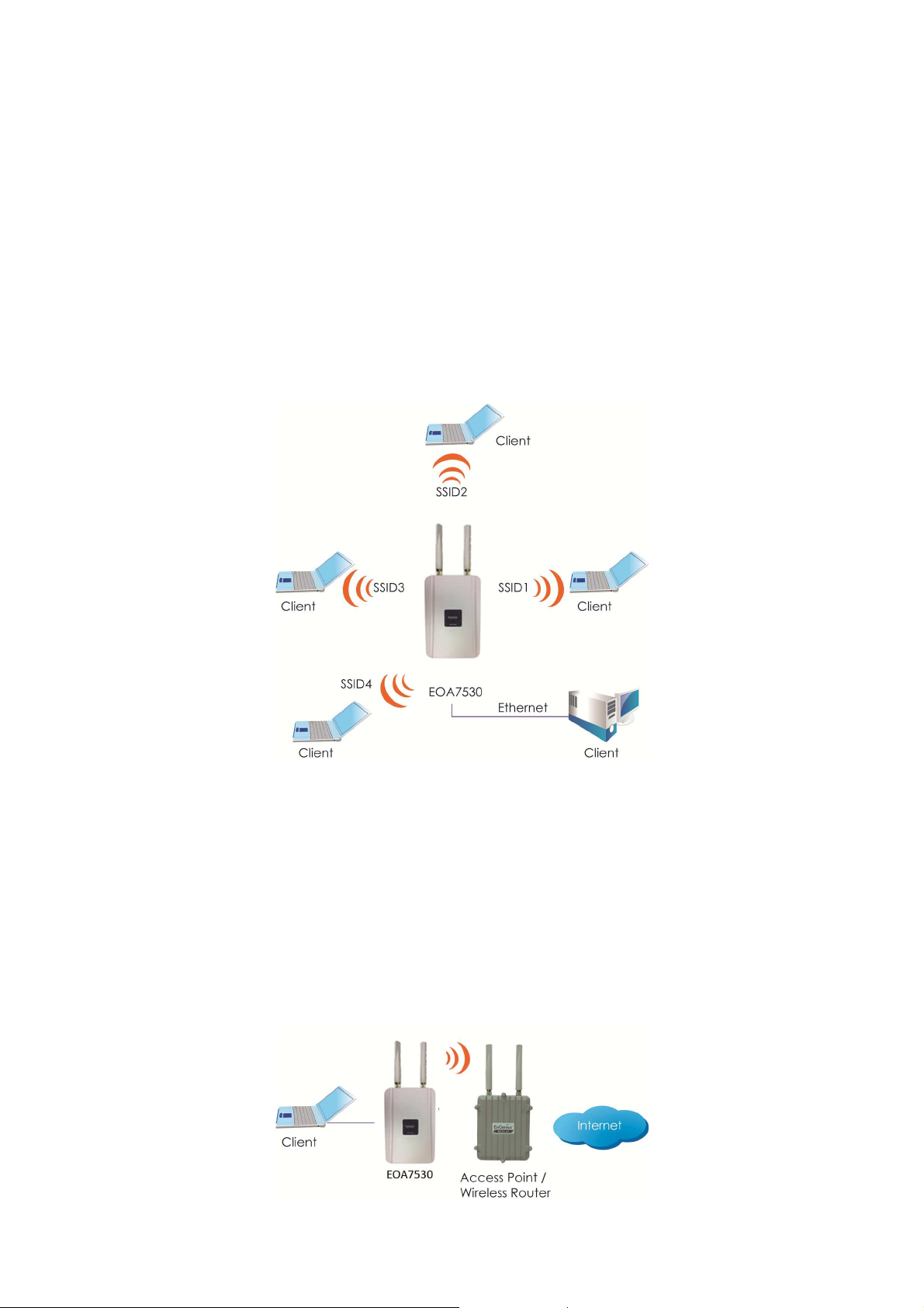
2.1 Access Point
In the Access Point Mode with WDS Function, EOA7530 function likes a central connection for any
stations or clients that support IEEE 802.11b/g network. Stations and Client must configure the same
SSID and Security Password to associate within the range. EOA7530 supports 4 different SSIDs to
separate different clients at the same time.
2.2 Client Bridge
In the Client Bridge Mode, the EOA7530 function likes a wireless dongle. Connected to an Access
Point wirelessly and surf internet whenever you want. Using Site Survey to scan all the Access Point
within the range and configure its SSID and Security Password to associate with it. Connect your
station to the LAN port of the EOA7530 via Ethernet.
7
Page 9
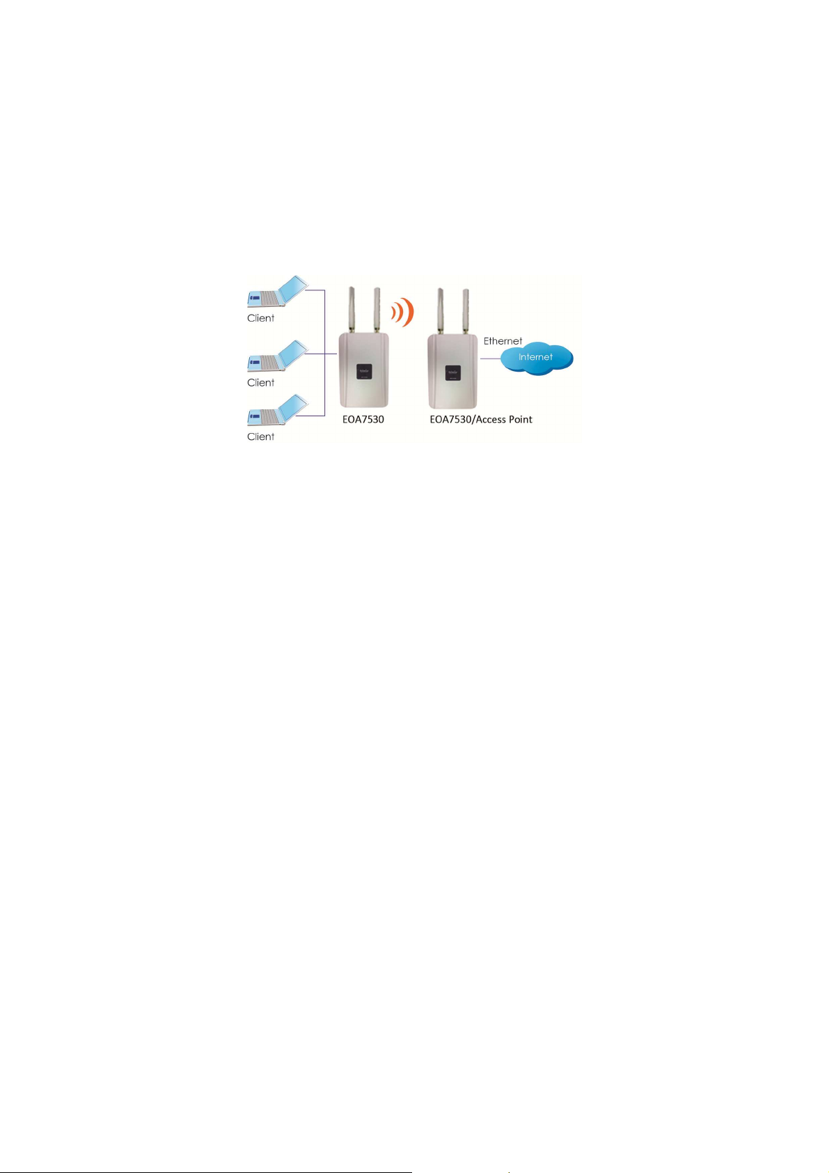
2.3 Client Router
In the Client Router Mode, the EOA7530 has DHCP Server build inside that allows many LANs
automatically generate an IP address to share the same Internet. Connect an AP/WISP Wirelessly and
connect to LANs via wired. Client Router Mode is act completely opposite to the AP Router Mode.
8
Page 10
3 Computer Configuration Instruction
3.1 Obtain an IP Automatically
In order to configure EOA7530, please follow the instruction below:
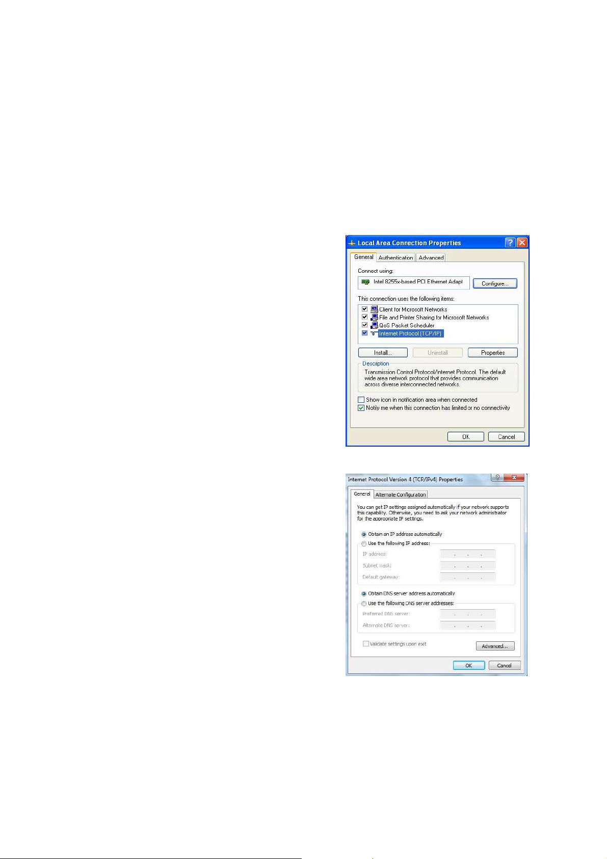
1. In the Control Panel, double click Network
Connections and then double click on the connection of
your Network Interface Card (NIC). You will then see the
following screen.
2. Select Internet Protocol (TCP/IP) and then click on the
Properties button. This will allow you to configure the
TCP/IP settings of your PC/Notebook
3. Select Obtain an IP Address automatically radio
button and then enter the IP address and subnet mask.
Ensure that the IP address and subnet mask are on the
same subnet as the device.
4. Click on the OK button to close this window, and then
close LAN properties window.
Auction: EOA7530 has provided DHCP server in the default setting. You should automatically retrieve
an IP address otherwise use an IP address which is in the same subnet as the device.
9
Page 11
3.2 Logging Method
After complete the IP settings from last section, you can now access the web-based configuration
menu.
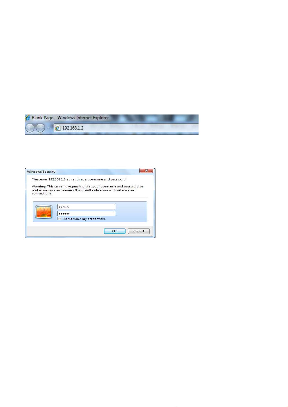
1. Open web browser
2. Enter IP 192.168.1.2 into you address filter.
Auction: If you have changed the EOA7530 LAN IP address, make sure you enter the correct IP
Address.
3. After connected to the EOA7530 successfully, browser will pop out a Windows Security window.
Please enter the correct Username and Password.
4. The default Username and Password are both admin.
Auction: If you have changed the Password, please enter your own Password. The Username cannot
be changed.
10
Page 12
4 Wireless Configuration
4.1 Switching Operation Mode
The EOA7530 supports 3 different operation modes: Access Point, Client Bridge, and Client Router.
Each mode can be used in both 2.4G and 5G wireless network at the same time or separately.
Click Operation Mode under Management Section to begin.
.
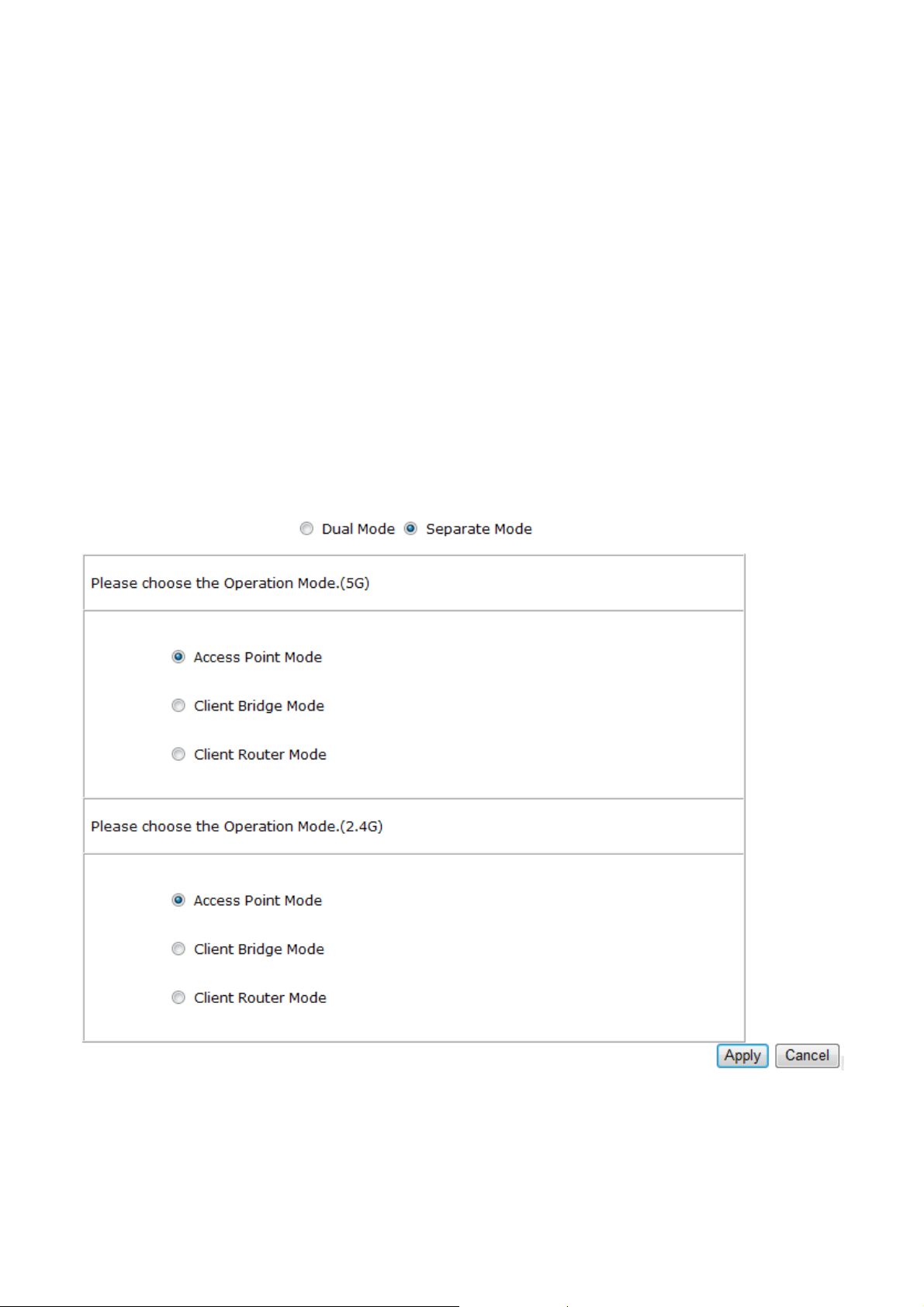
4.1.1 Separate Mode
5G’s and 2.4G’s networks can operate separately by selecting Separate Mode’s radio button.
Operation Mode (5G): Select which operation modes you would like to use in 5G network.
Operation Mode (2.4G): Select which operation modes you would like to use in 2.4G network.
Apply / Cancel: Press Apply to save the changes or Cancel to return previous settings.
Auction: Client Bridge Mode and Client Router Mode can not be used at the same time.
11
Page 13
Note: If you would like to use the Access Point mode in both 5G and 2.4G network, please check next
section for details.
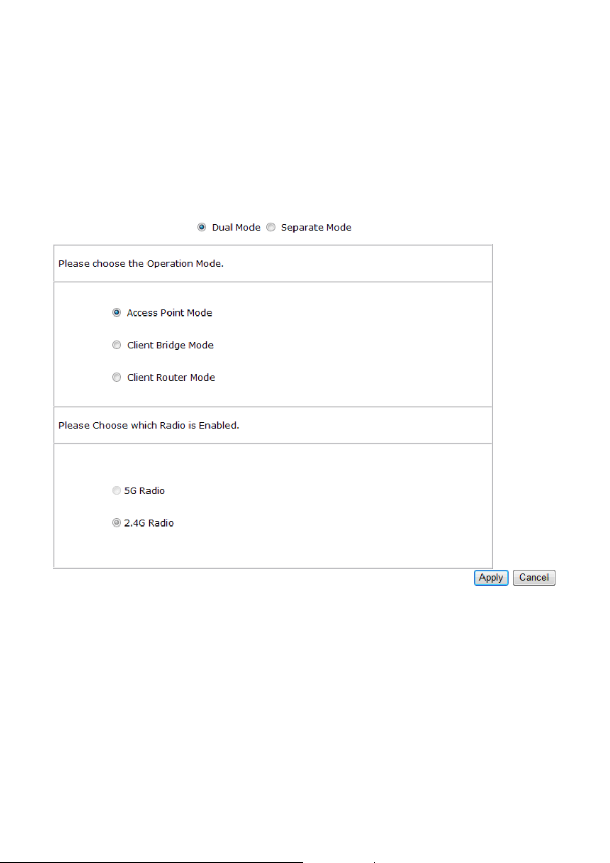
4.1.2 Dual Mode
Only Access Point Mode can operate 2.4G and 5G at the same time. However, Client Bridge/Client
Router can still select 2.4G and 5G network in the wireless basic settings. Please select the Dual
Mode’s radio button to begin.
Operation Mode: Only Access Point mode can be worked in 5G and 2.4G at the same time.
5G / 2.4G Radio Button: In the Access Point mode, the radio buttons will be locked because both
bands can work at the same time. Select the 5G or 2.4G radio button to access the wireless network.
You can still change bands in the wireless basic settings.
Apply / Cancel: Press Apply to save the changes or Cancel to return previous settings.
4.2 Wireless Settings
Configuration is under Wireless Section on the left-hand-side menu.
12
Page 14
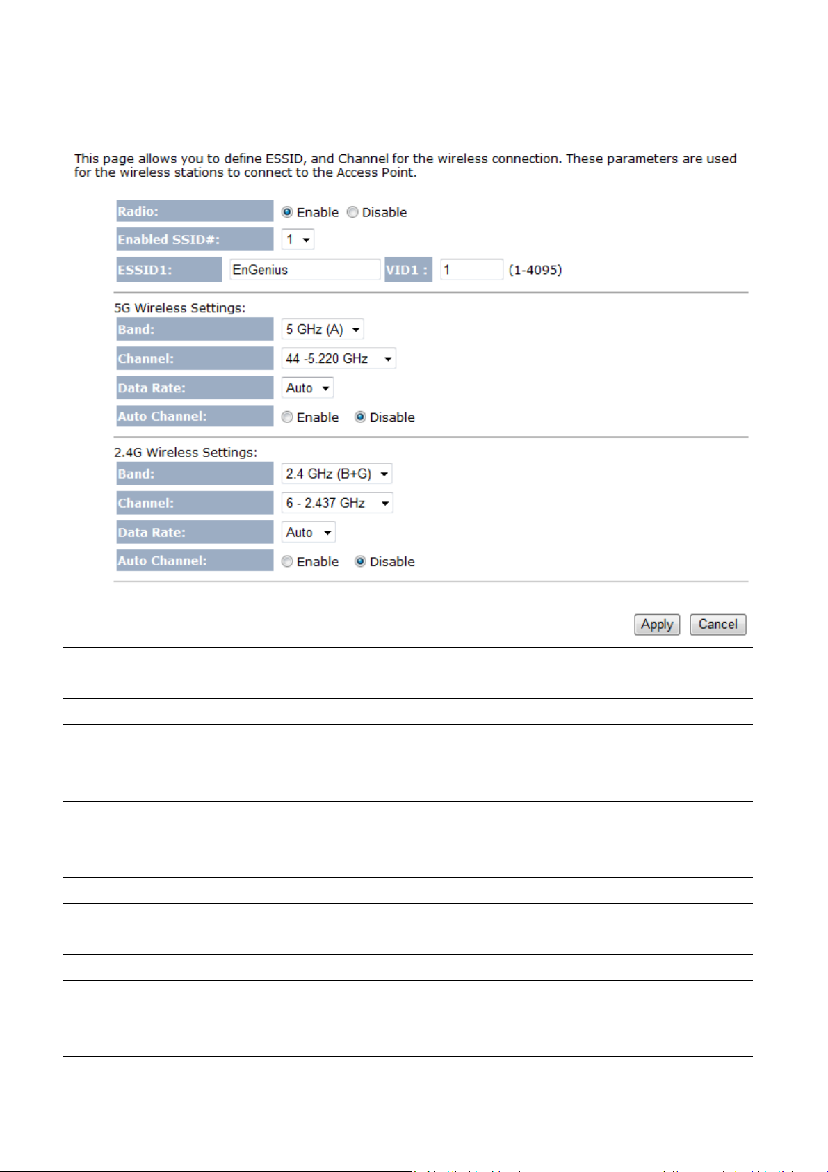
4.2.1 Access Point Mode (Dual Mode)
Radio
Enable SSID#
ESSID
5G Wireless Settings
Band
Channel
Data Rate
Auto Channel
2.4G Wireless Settings
Band
Channel
Data Rate
Select the radio button to enable or disable wireless function.
EOA7530 can support up to 4 different SSID with different VLAN tag.
Specify the broadcast SSID and VLAN ID for each ESSID.
Standard IEEE 802.11a band.
Select a channel from drop down menu.
Select the data rate from drop down menu. Data rate will affect the efficiency of the
throughput. If the data rate is set to a small number, the lower through will get but it
can transmit to longer distance.
Select the radio button to enable auto channel function.
Standard IEEE 802.11b and 802.11g band.
Select a channel from drop down menu.
Select the data rate from drop down menu. Data rate will affect the efficiency of the
throughput. If the data rate is set to a small number, the lower through will get but it
Auto Channel
can transmit to longer distance.
Select the radio button to enable auto channel function.
13
Page 15

Apply / Cancel
Press Apply to apply the changes or Cancel to return previous settings.
Auction: Both 5G and 2.4G bands are using the same SSID.
4.2.2 Access Point Mode (5G)
Radio
Enable SSID#
ESSID
Select the radio button to enable or disable wireless function.
EOA7530 can support up to 4 different SSID with different VLAN tag.
Specify the broadcast SSID and VLAN ID for each ESSID.
5G Wireless Settings
Band
Channel
Data Rate
Auto Channel
Apply / Cancel
Standard IEEE 802.11a band.
Select a channel from drop down menu.
Select the data rate from drop down menu. Data rate will affect the efficiency of the
throughput. If the data rate is set to a small number, the lower through will get but it
can transmit to longer distance.
Select the radio button to enable auto channel function.
Press Apply to apply the changes or Cancel to return previous settings.
Auction: If you do not have experience of data rate setting, please remain as default setting.
14
Page 16

4.2.3 Access Point Mode (2.4G)
Radio
Enable SSID#
ESSID
Select the radio button to enable or disable wireless function.
EOA7530 can support up to 4 different SSID with different VLAN tag.
Specify the broadcast SSID and VLAN ID for each ESSID.
2.4G Wireless Settings
Band
Channel
Data Rate
Auto Channel
Apply / Cancel
Standard IEEE 802.11b and 802.11g band.
Select a channel from drop down menu.
Select the data rate from drop down menu. Data rate will affect the efficiency of the
throughput. If the data rate is set to a small number, the lower through will get but it
can transmit to longer distance.
Select the radio button to enable auto channel function.
Press Apply to apply the changes or Cancel to return previous settings.
Auction: If you do not have experience of data rate setting, please remain as default setting.
15
Page 17

4.2.4 Client Bridge Mode/Client Router Mode (Dual Mode)
ESSID
Preferred BSSID
5G Wireless Setting
2.4G Wireless Setting
Apply / Cancel
Specify the SSID is given by Access Point if known. Otherwise, you may use Site
Survey to scan nearby Access Point.
Specify the MAC address from the Access Point that you would like to associate with.
Select the radio button to use 5G network as your default wireless network.
Select the radio button to use 2.4G network as your default wireless network.
Press Apply to apply the changes or Cancel to return previous settings.
Auction: EOA7530 can not operate Client Bridge in 5G and 2.4G at the same time.
Note: For more details of Site Survey, please refer to the Site Survey section.
16
Page 18

4.2.5 Client Bridge Mode/Client Router Mode (5G)
ESSID
Preferred BSSID
5G Wireless Setting
Apply / Cancel
Specify the SSID is given by Access Point if known. Otherwise, you may use Site
Survey to scan nearby Access Point.
Specify the MAC address from the Access Point that you would like to associate with.
Standard IEEE 802.11a wireless band.
Press Apply to apply the changes or Cancel to return previous settings.
Note: For more details of Site Survey, please refer to the Site Survey section.
4.2.6 Client Bridge Mode/Client Router Mode (2.4G)
ESSID
Preferred BSSID
2.4G Wireless Setting
Apply / Cancel
Specify the SSID is given by Access Point if known. Otherwise, you may use Site
Survey to scan nearby Access Point.
Specify the MAC address from the Access Point that you would like to associate with.
Standard IEEE 802.11b and IEEE 802.11g wireless band.
Press Apply to apply the changes or Cancel to return previous settings.
17
Page 19

Note: For more details of Site Survey, please refer to the Site Survey section.
4.3 Site Survey
Use this feature to scan nearby Access Point.
No
Select
Channel
SSID
BSSID
Encryption
Signal(dBm)
Refresh
Connect
Numbers of Access Points have been found in the site survey.
Select the Access Point you would like to associate with via select the radio button.
Access Point is currently uses which channel.
Access Point is broadcast the SSID.
Access Point’s wireless MAC address.
Access Point is currently uses which security type.
Signal strength from Access Point to your station.
Press Refresh to rescan nearby Access Point.
After you selected the radio button, press Connect to process the connection.
Auction: If you select 5G as your default wireless network, you can not scan the Access Point which is
operated in 2.4G band.
4.4 AP Scan List (5G / 2.4G)
This feature can help you to select the Access Point Channel by scan nearby Access Point status.
Refresh
Press Refresh to scan again.
4.5 Wireless Security Settings
Wireless Security Settings section will guide you to the entire Security modes configuration: WEP,
WPA(TKIP), WPA2(AES), WPA2-Mixed, and Radius. WPA(TKIP), WPA2(AES), and WPA2-Mixed are all
under WPA pre-shared key section.
18
Page 20

We are strongly recommended that uses WPA2-PSK AES as your security settings.
4.5.1 WEP (Access Point)
ESSID Selection
Hidden SSID
WMM
Encryption
Authentication Type
Key Length
Key Type
Default Key
Key1
Key2
Key3
Key4
EOA7530 supports up to 4 different SSIDs. Each SSID can be set to different
authentication type.
Select Enable or Disable broadcast SSID.
Select Enable or Disable WMM function. WMM is based on the four Access
Categories: voice, video, best effort and background. WMM function is not used to
guarantee transmission speed.
Select WEP from the drop down list to begin the configuration.
Select Open System or Shared Key as your authentication type.
Select Key Length in 64/128bit password length.
Select Input Type in Hex or ASCII.
Select the default index key for wireless security.
Specify password for security key index No.1.
Specify password for security key index No.2.
Specify password for security key index No.3.
Specify password for security key index No.4.
Apply / Cancel
Press Apply to save the changes or Cancel to return previous settings.
19
Page 21

4.5.2 WEP (Client Bridge / Client Router)
Network Name (SSID)
Encryption
Authentication Type
Key Length
Key Type
Default Key
Key1
Key2
Key3
Key4
Apply
Specify the Access Point’s SSID that you would like to associate with.
Select WEP from the drop down list to begin the configuration.
Select Open System or Shared Key as your authentication type.
Select Key Length in 64/128bit password length.
Select Input Type in Hex or ASCII.
Select the default index key for wireless security.
Specify password for security key index No.1.
Specify password for security key index No.2.
Specify password for security key index No.3.
Specify password for security key index No.4.
Press Apply to save the changes.
20
Page 22

4.5.3 WPA pre-shared Key (Access Point)
ESSID Selection
EOA7530 supports up to 4 different SSIDs. Each SSID can be set to different
authentication type.
Hidden SSID
WMM
Encryption
WPA Type
Pre-shared Key Type
Pre-shared Key
Apply / Cancel
Select Enable or Disable broadcast SSID.
Select Enable or Disable WMM function. WMM is based on the four Access
Categories: voice, video, best effort and background. WMM function is not used to
guarantee transmission speed.
Select WPA pre-shared Key from the drop down list to begin the configuration.
Select WPA(TKIP), WPA2(AES), or WPA2 Mixed as your authentication type.
Select Passphrase or Hex (64 characters) as your key type.
Specify password for security key.
Press Apply to save the changes or Cancel to return previous settings.
Auction: Hex key type does not allow special characters in the password.
21
Page 23

4.5.4 WPA pre-shared Key (Client Bridge / Client Router)
Network Name (SSID)
Encryption
WPA Type
Pre-shared Key Type
Pre-shared Key
Apply
Specify the Access Point’s SSID that you would like to associate with.
Select WPA pre-shared key from the drop down list to begin the configuration.
Select WPA(TKIP), or WPA2(AES) as your authentication type.
Select Passphrase or Hex (64 characters) as your key type.
Specify password for security key.
Press Apply to save the changes.
Auction: Hex key type does not allow special characters in the password.
22
Page 24

4.5.5 Radius (Access Point Only)
Radius authentication type is only available in Access Point Mode. Use this feature if you have Radius
Server. It also supports WPA(TKIP), WPA2(AES) and WPA2 Mixed encryption types.
ESSID Selection
Hidden SSID
WMM
Encryption
WPA Type
RADIUS Server IP Address
RADIUS Server Port
RADIUS Server Password
Apply / Cancel
EOA7530 supports up to 4 different SSIDs. Each SSID can be set to different
authentication type.
Select Enable or Disable broadcast SSID.
Select Enable or Disable WMM function. WMM is based on the four Access
Categories: voice, video, best effort and background. WMM function is not used to
guarantee transmission speed.
Select WPA RADIUS from the drop down list to begin the configuration.
Select WPA(TKIP), WPA2(AES), or WPA2 Mixed as your encryption type.
Specify your Radius Server’s IP address.
Specify your Radius Server Port number.
Specify the Radius Server’s password that used to negotiate with Radius server
authentication.
Press Apply to save the changes or Cancel to return previous settings.
23
Page 25

4.6 Wireless Advanced Settings
If you do not have experience with Wireless Advanced Settings, we suggest remain all settings to
default. Any modifies may cause insufficient wireless connection quality.
4.6.1 Advanced Settings (Access Point)
Fragment Threshold
RTS Threshold
Beacon Interval
DTIM Period
Preamble Type
Specify package size during transmission. If large amount of client are accessing to
the network, specify small number of the fragment length in order to avoid collision.
Specify Threshold package size for Request To Send (RTS). Using small number of the
threshold will cause RTS packets to be sent more often to consuming more of the
available bandwidth. In addition, if the heavy load traffic occurs, the wireless
network can be recovered easily from interferences or collisions.
Specify the time of Beacon Interval. Beacon is used to let wireless client scan the
wireless AP is available. Site Survey scans the Beacon to verify which AP is in the
nearby area.
Delivery Traffic Indication Map (DTIM) is for the Power Saving purpose. Access Point
sends the packet with beacon frame in the period of time. If the DTIM sets larger
number, the wireless client may affect the latency throughput but save more power.
Select the Radio button to choose Long Preamble or Short Preamble. Long Preamble
can increase the capability of wireless network and wireless signal range. Short
Preamble can increase the efficiency of the wireless network.
Tx Power
Select Tx Power to increase or decrease Transmit Power. Higher transmit power will
24
Page 26

sometimes cause unable to connect to the network. On the other hand, the lower
transmit power will cause client unable to connect to the device.
Distance
Layer 2 Isolation
Specify distance rage between AP and Clients. Longer distance may lose high
connection speed.
Select the Radio button to enable or disable Layer 2 Isolation. Layer 2 isolation
prevents communication between wireless stations associated to different APs
4.6.2 Advanced Settings (Client Bridge / Client Router)
Fragment Threshold
RTS Threshold
Preamble Type
802.11g Protection
Tx Power
Specify package size during transmission. If large amount of client are accessing to
the network, specify small number of the fragment length in order to avoid collision.
Specify Threshold package size for Request To Send (RTS). Using small number of the
threshold will cause RTS packets to be sent more often to consuming more of the
available bandwidth. In addition, if the heavy load traffic occurs, the wireless
network can be recovered easily from interferences or collisions.
Select the Radio button to choose Long Preamble or Short Preamble. Long Preamble
can increase the capability of wireless network and wireless signal range. Short
Preamble can increase the efficiency of the wireless network.
Select the Radio button to Protect types. When enable the protection mode, every
time the packet is transmitted, it has to wait the CTS is received. In addition,
Protection mode can prevent the collision but it will slow the wireless transmission
speed.
Select Tx Power to increase or decrease Transmit Power. Higher transmit power will
sometimes cause unable to connect to the network. On the other hand, the lower
transmit power will cause client unable to connect to the device.
Distance
Specify distance rage between AP and Clients. Longer distance may lose high
connection speed.
25
Page 27

4.7 Wireless Access Control List
Wireless Access Control List is used to Allow or Deny wireless clients by their MAC addresses,
accessing the Network. You can manually add a MAC address to restrict the permission to access
EOA7530.
Enable Wireless Access
Control
Description
MAC Address
Add
Reset
MAC Address Filtering
Table
Delete Selected
Delete All
Reset
Apply / Cancel
5 LAN Setup
Place a Check to enable Wireless Access Control.
Specify the description for the MAC address you about to add.
Specify the MAC Address.
Press Add to add the MAC address.
Press Reset to cancel the condition of description and MAC Address.
Check all the conditions you had added.
Place a Check at Select section, and then press Delete Selected to delete the option.
Press Delete All to erase all options in the table.
Press Reset to cancel the selection.
Press Apply to save the changes or Cancel to return previous settings.
This section will guide you to the Local Area Network (LAN) settings
26
Page 28

5.1 LAN Settings
Auction: Changing LAN IP Address will change LAN Interface IP address. Webpage will automatically
redirect to the new IP address after Apply.
LAN IP
IP Address
IP Subnet Mask
Default Gateway
802.1d Spanning Tree
Specify LAN port IP address.
Specify Subnet Mask.
Specify Default Gateway
Select the drop down menu to enable or disable Spanning Tree.
DHCP Server
DHCP Server
Lease Time
Start IP
End IP
Domain Name
Apply / Cancel
Select the drop down menu to enable or disable DHCP server.
Specify the expiring time of IP address given by DHCP server.
Specify IP Pool’s first IP.
Specify IP Pool’s last IP.
Specify the Domain Name of the device.
Press Apply to apply the changes or Cancel to return previous settings.
Auction: If you have disabled the DHCP Server, you must configure your PC’s local IP in order to
access the web-based interface. Start IP and End IP must at the same subnet.
27
Page 29

5.2 DHCP Info
Click on the DHCP Info link under the TCP/IP section. This page displays the list of Clients that are
associated to the EOA3630 through DHCP. You can also assign an IP address for certain MAC
Address.
The IP Address, MAC Address and Expiration Time for each IP Address are displayed. Click on the
Refresh button to refresh the client list.
Enable Static DHCP IP
IP Address
MAC Address
Add
Reset
Current Static DHCP Table
Delete Selected
Delete All
Reset
Apply / Cancel
Place a Check to enable Static DHCP IP.
Specify the IP Address for the MAC address you about to add.
Specify the MAC Address.
Press Add to add the MAC address.
Press Reset to cancel the condition of description and MAC Address.
Check all the conditions you had added.
Place a Check at Select section, and then press Delete Selected to delete the option.
Press Delete All to erase all options in the table.
Press Reset to cancel the selection.
Press Apply to save the changes or Cancel to return previous settings.
28
Page 30

5.3 SNMP Settings
SNMP Enable
Select the Radio button to enable SNMP feature.
SNMP Disable
Apply / Cancel
Select the Radio button to disable SNMP feature.
Press Apply to apply the changes or Cancel to return previous settings.
29
Page 31

6 Internet Settings
6.1 DHCP (Dynamic IP)
Select Dynamic IP as your WAN connection type to obtain your IP address automatically. You will
need to enter Hostname
Hostname
Apply / Cancel
Specify the Hostname is given by your Internet Service Provider.
Press Apply to apply the changes or Cancel to return previous settings.
6.2 Static IP
Select Static IP in WAN connection if your ISP gives all the information about IP address, Subnet Mask,
Default Gateway, Primary DNS and Secondary DNS.
IP Address
IP Subnet Mask
Gateway IP Address
Primary DNS
Secondary DNS
Apply / Cancel
Specify WAN port IP address.
Specify WAN IP Subnet Mask.
Specify WAN Gateway IP address.
Specify Primary DNS IP.
Specify Secondary DNS IP.
Press Apply to apply the changes or Cancel to return previous settings.
30
Page 32

6.3 PPPoE (Point-to-Point Protocol over Ethernet)
Select PPPoE as your WAN connection type if your ISP provides Username and Password. PPPoE is a
DSL service and please remove your PPPoE software from your computer, the software is not worked
in EOA3630.
Login
Password
Service Name
MTU
Authentication Type
Type
Idle Timeout
Apply / Cancel
Specify the Username that is given by your ISP.
Specify the Password that is given by your ISP.
Specify the Service Name that is given by your ISP.
Specify the Maximum Transmit Unit size. Suggest remain in Auto.
Select the PAP, CHAP, or Auto as your encryption type from drop down menu.
Select Connection Type from drop down menu.
Keep Connection: Device is connected to internet automatically.
Automatic Connection: Device is automatically connected to internet when the
traffic goes through internet but it will disconnect when a period of idle time
Manual Connection: Connect to internet manually.
Specify the maximum idle time for Automatic Connection.
Press Apply to apply the changes or Cancel to return previous settings.
Auction: If the router's MTU is set too high, packets will be fragmented downstream. If the router's
MTU is set too low, the router will fragment packets unnecessarily and in extreme cases may be
unable to establish some connections. In either case, network performance can suffer.
31
Page 33

6.4 PPTP (Point-to-Point Tunneling Protocol)
Select PPTP as your WAN connection type if your ISP provides information about IP Address, Subnet
Mask, Default Gateway (Optional), DNS (Optional), Server IP, Login Username, and Login Password.
There are two types of PPTP connection: Dynamic IP Address and Static IP Address.
Dynamic IP Address
WAN Interface Type
Hostname
Static IP Address
WAN Interface Type
IP Address
IP Subnet Mask
Gateway IP Address
Select Dynamic IP Address as your WAN Interface.
Specify the Hostname is given by your Internet Service Provider.
Select Static IP Address as your WAN Interface.
Specify WAN port IP address.
Specify WAN IP Subnet Mask.
Specify WAN Gateway IP address.
32
Page 34

Login
Password
Service IP Address
Connection ID
MTU
Type
Idle Timeout
Enable PPTP pass through
on VPN Connection
Enable IPSec pass through
on VPN Connection
Enable L2TP pass through
Specify the Username that is given by your ISP.
Specify the Password that is given by your ISP.
Specify the Service IP Address that is given by your ISP.
Specify the Connection ID that is given by your ISP.
Specify the Maximum Transmit Unit size. Suggest remain in Auto.
Select Connection Type from drop down menu.
Keep Connection: Device is connected to internet automatically.
Automatic Connection: Device is automatically connected to internet when the
traffic goes through internet but it will disconnect when a period of idle time
Manual Connection: Connect to internet manually.
Specify the maximum idle time for Automatic Connection.
Place a Check to enable PPTP pass through on VPN Connection. If this feature
disabled, it will cause unable to connect to internet via PPTP.
Place a Check to enable IPSec pass through on VPN Connection. If this feature
disabled, it will cause unable to transmit IPSec Protocol.
Place a Check to enable L2TP pass through on VPN Connection. If this feature
on VPN Connection
Apply / Cancel
disabled, it will cause unable to connect to internet via L2TP.
Press Apply to apply the changes or Cancel to return previous settings.
Auction: If the router's MTU is set too high, packets will be fragmented downstream. If the router's
MTU is set too low, the router will fragment packets unnecessarily and in extreme cases may be
unable to establish some connections. In either case, network performance can suffer.
33
Page 35

7 Information Status
Status section is used to check the status of device information such as System up time, Firmware
version, Wireless Client List, and Internet Status.
7.1 Status
Click on the Status link under the Management section. This page display information of the device
such as Current Time, Hardware Version, Kernel Version, and Application version are displayed in the
‘System’ section. LAN IP address, Subnet Mask, DHCP Status, and MAC address are displayed in the
‘LAN Settings’ section. Access Point, Client Bridge and Client Router’s basic settings are displayed in
the “Wireless Information” section.
34
Page 36

7.2 Wireless Client List
Click on the Client List link under the 5G/2.4G Wireless section. This page displays the list of Clients
that are associated to the EOA7530.
The MAC addresses, signal strength, and Idle Time for each client is displayed. Click on the Refresh
button to refresh the client list
7.3 System Log
Click on the Log link under the Management section. The device automatically logs (records) events
of possible interest in its internal memory. If there is not enough internal memory for all events, logs
of older events are deleted, but logs of the latest events are retained. You can Save your current
system operation information to a text file or clear all logs.
35
Page 37

7.4 Internet Status
Click on the Status link under the Internet section. This page displays the current connection type
status of the network, including network type, SSID, BSSID, connection status, wireless mode,
current channel, security, data rate, noise level and signal strength.
Note: If your internet connection type is PPPoE or PPTP with Manual Connection, you can connect to
internet at this page.
36
Page 38

8 Management Settings
Management section is on the navigation drop-down menu. This section can help you to manage
your device and adjust system settings such as Password, Time Zone, Diagnosis, Remote Control,
Upgrade Firmware, Save/Load Settings. Each option is described below.
8.1 Password Settings
Click on the Password link under the Management section. This option allows you to change
password for the device. By default, the default password is admin. For security reasons it is highly
recommended that you create a new password.
Old Password
New Password
Repeat New Password
Apply / Cancel
Enter the current password.
Specify a new Password for login
Re-enter the new Password for confirmation.
Press Apply to apply the changes or Cancel to return previous settings.
8.2 Time Zone Settings
Click on the Time Zone link under the Management menu. This page allows you to configure the
time on the device.
Time Zone
Select your Country or Region from the drop down list.
37
Page 39

NTP Time Server
Specify the NTP Server’s Domain name or IP Address.
Daylight Saving
Apply / Cancel
Place a Check to enable Daylight Saving feature. Configure the starting date and
ending date.
Press Apply to save the changes or Cancel to return previous settings.
8.3 Diagnosis
Click on the Diagnostics link under the Management menu. This function allows you to detect
connection quality and trace the routing table to the target.
Address to Ping
Start
Count
Ping Result
Specify the IP address you would like to Ping.
Press Start to begin.
Specify numbers of time to ping.
Display Ping result.
38
Page 40

8.4 Remote Control
Host Address
Specify the IP Address you would like to use as your remote controller.
Port
Enable
Apply/Reset
Specify the Port number.
Place a Check to enable Remote management.
Press Apply to save the changes or Reset to return previous settings.
8.5 Upgrade Firmware
Click on the Upgrade Firmware link under the Management menu. This page is used to upgrade the
firmware of the device. Make sure that downloaded the appropriate firmware from your vendor.
Auction: Upgrade process may take few minutes, please do not power off the device and it may cause
the device crashed or unusable. EOA7530 will restart automatically once the upgrade is completed.
8.6 Save/Reload Settings
Click on the Save/Reload Setting link under the Management menu. This option is used to save the
current settings of the device in a file to your local disk or load settings to the device from your local
disk. This feature is very handy for administrators who have several devices that need to be
configured with the same settings.
39
Page 41

Restore to Factory
Default Settings
Click on Reset button to reset all the settings to the default values.
Backup Settings
Restore Settings
Restart
Click on Save to save current configured settings.
EOA7530 can restore a previous setting that has been saved. Click on Browse to
select the file and Upload.
Press Restart to reboot the device.
Auction: If you choose to Restore to Factory Default, all the settings will be erased. It is strongly
suggested to save current settings before your process.
40
Page 42

9 Network Configuration Example
This chapter describes the role of the EOA7530 with three different modes. The Access Point mode’s
default configuration is a central unit of the wireless network or as a root device of the wired
environment. Repeater mode and Mesh network mode need future configuration.
9.1 Access Point Mode + Client Bridge Mode
Access Point
Step1 Login to the web-based configuration interface with default IP 192.168.1.2
Step2 Select 802.11b/g mixed and/or 802.11a as your wireless mode.
Step3 Use AP Scan to scan channels that have been used in nearby area.
Step4 Select channel with less interferences.
Step5
Step6 Verify VLAN identifier to separate services among clients
Step7 Setup the authentication settings.
Step8 Press Apply to save all changes.
Auction: Dual mode uses the same SSID on 5G and 2.4G wireless network.
Note: For more advanced settings, please refer to the previous chapters.
Specify the SSID for your broadcast SSID and you can also configure multiple SSID at
the same time.
Client Bridge
Step1 Login to the web-based configuration interface with default IP 192.168.1.2
Step2 Change operation mode to Client Bridge.
41
Page 43

Step3 Select 5G or 2.4G as your wireless mode.
Step4
Step5 Select correct authentication type and then enter password.
Auction: Wireless Client IP address must configure manually at the same subnet in Local Area Network or enable DHCP
server of EOA7530 to retrieve IP automatically.
Use site survey to scan nearby Access Point and select the certain AP you would like
to connect with or enter SSID manually.
9.2 Client Router Mode
Please refer to last section for the configuration of Access Point.
Step1 Login to the web-based configuration interface with default IP 192.168.1.2
Step2 Change operation mode to Client Router.
Step3 Select 5G or 2.4G as your wireless mode.
Step4 Use site survey to scan nearby Access Point and select the certain AP you would like
to connect with or enter SSID manually.
Step5 Select correct authentication type and then enter password.
Step6 Select your internet connection type base on your Internet Service Provider.
Note: For more details of Internet Connection Settings, Please refer to the Internet chapter.
42
Page 44

Appendix A – FCC Interference Statement
Federal Communication Commission Interference Statement
This equipment has been tested and found to comply with the limits for a Class B digital device, pursuant to Part 15
of the FCC Rules. These limits are designed to provide reasonable protection against harmful interference in a
residential installation. This equipment generates, uses and can radiate radio frequency energy and, if not installed
and used in accordance with the instructions, may cause harmful interference to radio communications. However,
there is no guarantee that interference will not occur in a particular installation. If this equipment does cause
harmful interference to radio or television reception, which can be determined by turning the equipment off and on,
the user is encouraged to try to correct the interference by one of the following measures:
- Reorient or relocate the receiving antenna.
- Increase the separation between the equipment and receiver.
- Connect the equipment into an outlet on a circuit different from that
to which the receiver is connected.
- Consult the dealer or an experienced radio/TV technician for help.
FCC Caution: Any changes or modifications not expressly approved by the party responsible for compliance could
void the user's authority to operate this equipment.
This device complies with Part 15 of the FCC Rules. Operation is subject to the following two conditions: (1) This
device may not cause harmful interference, and (2) this device must accept any interference received, including
interference that may cause undesired operation.
IMPORTANT NOTE:
FCC Radiation Exposure Statement:
This equipment complies with FCC radiation exposure limits set forth for an uncontrolled environment. This
equipment should be installed and operated with minimum distance 20cm between the radiator & your body.
This transmitter must not be co-located or operating in conjunction with any other antenna or transmitter.
43
 Loading...