

Page 1
User Manual
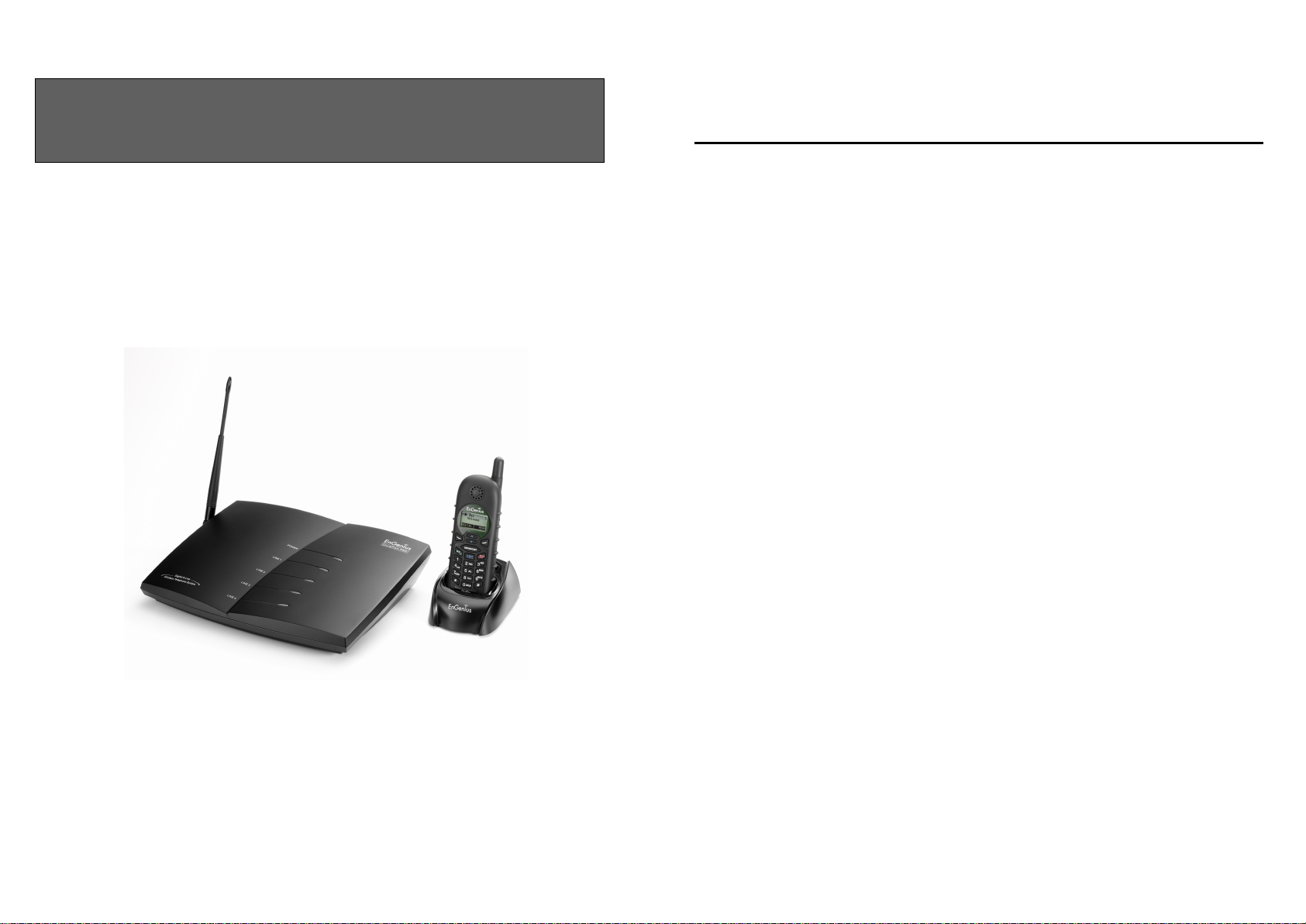
DuraFon PRO
Table of Contents
User Manual
Digital Long Range Industrial Cordless System
SAFETY INSTRUCTIONS ..................................................................................... 4
GENERAL SAFETY INSTRUCTIONS .................................................................................... 4
PRODUCT SAFETY INSTRUCTIONS .................................................................................... 4
BATTERY SAFETY INSTRUCTIONS ..................................................................................... 6
REGULATORY INFORMATION ......................................................................... 7
EQUIPMENT CHECKLIST ................................................................................ 11
HANDSET ILLUSTRATION ............................................................................... 13
HANDSET FEATURES ........................................................................................ 13
BASIC HANDSET FEATURES ............................................................................................ 14
ADDITIONAL HANDSET FEATURES ................................................................................. 16
BASE ILLUSTRATION ........................................................................................ 20
BASIC BASE STATION FEATURES .................................................................................... 21
ADDITIONAL BASE STATION FEATURES .......................................................................... 22
ADMINISTRATOR FEATURES ........................................................................................... 22
CHARGER ILLUSTRATION .............................................................................. 23
CHARGER FEATURES ....................................................................................... 24
OPTIONAL DURAFON PRO PLATFORM PRODUCTS ................................ 25
1. DURAWALKIE HANDSET ............................................................................................ 25
2. DURAFON UHF HANDSET .......................................................................................... 25
3. DURAFON PSL ........................................................................................................... 25
BASE STATION INSTALLATION ...................................................................... 27
HANDSET AND CHARGER INSTALLATION ................................................. 30
BASIC OPERATIONS .......................................................................................... 32
OPERATION MODES ........................................................................................................ 32
A. Base Operation Modes ......................................................................................... 32
2
Page 2

B. Handset Operation Modes .................................................................................... 32
MENU TREE ................................................................................................................... 33
MAKING A TELEPHONE CALL (FOR DURAFON PRO ONLY) ............................................ 35
MAKING A 2-WAY/ INTERCOM CALL .............................................................................. 35
Handset to Handset Calls .......................................................................................... 35
MAKING A BROADCAST ................................................................................................. 36
REDIAL (FOR DURAFON PRO ONLY) ............................................................................. 37
RECEIVING A TELEPHONE CALL (FOR DURAFON PRO ONLY) ........................................ 37
RECEIVING AN INTERCOM CALL .................................................................................... 38
ENDING A CALL.............................................................................................................. 38
ADJUSTING RECEIVER (EARPIECE) VOICE VOLUME ....................................................... 38
PLACING A CALL ON HOLD (FOR DURAFON PRO ONLY) ............................................... 39
MUTE ............................................................................................................................. 39
DO NOT DISTURB (SILENT RING) ................................................................................... 40
KEY GUARD ................................................................................................................... 40
TO VIEW MISSED CALL(S) (FOR DURAFON PRO ONLY) ................................................ 40
TO CALL BACK FROM CALL LOG (FOR DURAFON PRO ONLY) ....................................... 40
BATTERY RECHARGE AND REPLACEMENT ...................................................................... 41
ADVANCED OPERATIONS ................................................................................ 42
HANDSET REGISTRATION ............................................................................................... 42
ADVANCED REGISTRATION: ........................................................................................... 43
HANDSET GROUP SUBSCRIPTION ................................................................................... 44
CALL TRANSFER (FOR DURAFON PRO ONLY) ............................................................... 45
3-WAY CONFERENCING (FOR DURAFON PRO) .............................................................. 45
BASE SELECT (FOR DURAFON PRO ONLY) .................................................................... 46
CALL WAITING (FOR DURAFON PRO ONLY) .................................................................. 47
VISUAL MESSAGE WAITING INDICATOR (VMWI) .......................................................... 48
AUTO ATTENDANT (AA) ................................................................................................ 48
AA CONFIGURATION BY ADMINISTRATOR ...................................................................... 50
CHANGE AA PARAMETERS ............................................................................................. 50
LINE DEDICATION .......................................................................................................... 51
LINE SELECTION (FOR DURAFON PRO ONLY) ............................................................... 52
CHANGE SYSTEM AND LINE SETTINGS BY ADMINISTRATOR ........................................... 52
PHONEBOOK OPERATIONS .............................................................................................. 53
BROADCAST THROUGH PBX .......................................................................................... 57
REPEATER OPERATION ................................................................................................... 58
MENU OPERATIONS .......................................................................................... 60
TECHNICAL SPECIFICATIONS .......................................................................................... 69
Safety Instructions
Caution: Your wireless telephone gives you freedom and flexibility to stay
in touch while you move around. However, when using your phone
equipment, safety instructions should be followed to avoid the risks of
fire, electric shock, injury to person, and damage to property.
General Safety Instructions
1. When using your wireless phone, ensure your safety and the safety of others:
a. Always watch where you are walking and standing.
b. Don’t let a phone call distract you from working safely.
c. If power goes out, it won’t work. Recommend backup power.
2. In an emergency:
a. If an emergency occurs, dial the emergency phone number. Remember: if you
are in an area where your phone does not have a clear signal from the base, it is
highly probable that the call may not go through. Locate the nearest landline
telephone or other communications device to call for help.
b. Emergency calls may not automatically provide emergency personnel with your
name, phone number or location.
3. Notice to Hearing Aid Users: This phone system is compatible with inductively
coupled hearing aids.
4. Notice to Cardiac Pacemaker Users: Preliminary studies done by the US FDA and
others have shown that, although interference to the implanted cardiac pacemaker
may occur when operating very closely, wireless telephones “do not seem to pose a
significant problem for pacemaker wearers.” However, until more is known, FDA
suggests that people with pacemakers may want to take precautions when using or
carrying a wireless telephone to ensure that there is ample distance between the
telephone and the pacemaker. Do not carry the handset in a breast pocket. If you
have any reason to suspect that interference is taking place, turn off your handset
immediately.
Product Safety Instructions
1. Read and understand all instructions.
2. Follow all warnings and instructions including those marked on the product.
3
4
Page 3

3. Changes or modifications to this product not expressively approved by the
manufacturer will void the warranty and the FCC authorization to operate the
equipment. Use only manufacturer provided accessories.
4. Do not use the telephone near water. Never spill liquid of any kind on this product.
5. Unplug the product from the wall telephone jack and power outlet before cleaning.
Do not use liquid or aerosol cleaners. Use damp cloth for cleaning.
6. Do not place this product on an unstable cart, stand, or table. The product may fall
and cause personal injury or damage to the product or other property.
7. Power Outage: In the event of a power outage, your handset charger will not
recharge the handset battery, and the base station will not allow you to make an
outgoing call or take an incoming call. Both the charger and the base station require
electricity for operation. You should have a telephone that does not require
electricity available for use during power outage, or have a temporary backup power
supply.
8. Slots or openings in the product’s housing are provided for ventilation. These
openings must not be blocked or covered. Placing the product on a bed, carpeting,
or other similar surface may block these openings and should be avoided. This
product should never be placed near or over a radiator or heat register, or in a builtin installation unless proper ventilation is provided.
9. Never push objects of any kind into this product through housing slots/openings as
they may damage the product, touch dangerous voltage points or short out parts
that could result in fire, electric shock, or injury.
10. This product should be operated only from the type of power source indicated on the
marking label. If you are not sure of the type of power supply to your home, consult
your dealer or local power company.
11. Do not overload wall power outlets and extension cords as this may result in fire or
electric shock.
12. To avoid electric shock or burn, do not disassemble this product. Send this product
to an authorized service center when service or repair work is required. Call
Customer Service for locations near you. Opening or removing covers may expose
you to dangerous voltages, electrical currents or other risks. Incorrect reassembling
of the product may cause electric shock when the product is subsequently used.
13. Avoid using the product during a storm. There may be a risk of electric shock from
lightning.
14. Do not place the product where persons can step, trip, or fall on it.
15. Do not place conductive objects over or near the antenna.
16. Do not use the product to report a gas leak while in the vicinity of the leak.
17. Do not install the base station or the handset charger near microwave ovens, radios,
TV sets, speakers, or other electrical equipment. These appliances may cause
interference to the product or experience interference from the product.
18. Unplug the base station or the charger adaptor from the power outlet and refer to an
authorized service center under the following conditions:
a. If liquid has been spilled into the product.
b. When the power supply cord or plug is damaged or frayed.
c. If the product has been exposed to rain or water.
d. If the product does not operate normally by following the operating instructions.
e. If the product has been dropped or housing has been damaged.
f. If the product shows a distinct change in performance.
Battery Safety Instructions
1. Use only manufacturer approved Li-ion rechargeable batteries and charger. Do not
use other types of rechargeable batteries or non-rechargeable batteries. The
batteries could short-circuit, and the battery enclosure may be damaged causing a
hazardous condition.
2. Follow the charging instruction in this manual and instruction labels and markings in
the handset and charger compartments.
3. Battery must be recycled or disposed of properly. Do not dispose the battery in a fire.
The cells may explode.
4. Do not dispose of the battery in municipal waste. Check with local codes for disposal
instructions.
5. Exercise care in handling the batteries in order not to short-circuit the battery with
conductive materials such as rings, bracelets, keys, pocketknife, and coins. The
battery or conductive material may overheat and cause burn or fire.
6. Do not expose batteries to rain or water.
7. Do not open or mutilate the battery. Released electrolyte is corrosive and may cause
injury to eyes or skin. The electrolyte may be toxic if swallowed.
8. During charging, the battery heats up. This is normal and is not dangerous.
5
6
Page 4

Regulatory Information
DuraFon PRO & DuraWalkie
FCC ID: A8J-SP922PROV3
IC: 10103A-SP922PROV3
This device complies with Part 15 of the FCC Rules. Operation is subject to
the following two conditions:
1) this device may not cause harmful interference, and
2) this device must accept any interference received, including
interference that may cause undesired operation.
Privacy of communications may not be ensured when using this phone.
Base Station
Federal Communication Commission Interference Statement
This equipment has been tested and found to comply with the limits for a Class B
digital device, pursuant to Part 15 of the FCC Rules. These limits are designed to
provide reasonable protection against harmful interference in a residential
installation. This equipment generates uses and can radiate radio frequency energy
and, if not installed and used in accordance with the instructions, may cause harmful
interference to radio communications. However, there is no guarantee that
interference will not occur in a particular installation. If this equipment does cause
harmful interference to radio or television reception, which can be determined by
turning the equipment off and on, the user is encouraged to try to correct the
interference by one of the following measures:
- Reorient or relocate the receiving antenna.
- Increase the separation between the equipment and receiver.
- Connect the equipment into an outlet on a circuit different from that to which the
receiver is connected.
- Consult the dealer or an experienced radio/TV technician for help.
FCC Caution: Any changes or modifications not expressly approved by the party
responsible for compliance could void the user's authority to operate this equipment.
This device complies with Part 15 of the FCC Rules. Operation is subject to the
following two conditions: (1) This device may not cause harmful interference, and (2)
this device must accept any interference received, including interference that may
cause undesired operation.
IMPORTANT NOTE:
FCC Radiation Exposure Statement:
This equipment complies with FCC radiation exposure limits set forth for an
uncontrolled environment. This equipment should be installed and operated with
minimum distance 20cm between the radiator & your body.
This transmitter must not be co-located or operating in conjunction with any other
antenna or transmitter.
Industry Canada statement:
This device complies with RSS-210 of the Industry Canada Rules. Operation is subject
to the following two conditions:
(1) This device may not cause harmful interference, and (2) this device must accept
any interference received, including interference that may cause undesired operation.
IMPORTANT NOTE:
Radiation Exposure Statement:
This equipment complies with IC radiation exposure limits set forth for an
uncontrolled environment. This equipment should be installed and operated with
minimum distance 20cm between the radiator & your body.
This device has been designed to operate with an antenna having a maximum gain of
2 dBi. Antenna having a higher gain is strictly prohibited per regulations of Industry
Canada. The required antenna impedance is 50 ohms.
Portable Handset
Federal Communication Commission Interference Statement
This equipment has been tested and found to comply with the limits for a Class B
digital device, pursuant to Part 15 of the FCC Rules. These limits are designed to
provide reasonable protection against harmful interference in a residential
installation. This equipment generates, uses and can radiate radio frequency energy
and, if not installed and used in accordance with the instructions, may cause harmful
interference to radio communications. However, there is no guarantee that
interference will not occur in a particular installation. If this equipment does cause
harmful interference to radio or television reception, which can be determined by
turning the equipment off and on, the user is encouraged to try to correct the
interference by one of the following measures:
7
8
Page 5

- Reorient or relocate the receiving antenna.
- Increase the separation between the equipment and receiver.
- Connect the equipment into an outlet on a circuit different from that to which the
receiver is connected.
- Consult the dealer or an experienced radio/TV technician for help.
FCC Caution: Any changes or modifications not expressly approved by the party
responsible for compliance could void the user's authority to operate this equipment.
This device complies with Part 15 of the FCC Rules. Operation is subject to the
following two conditions: (1) This device may not cause harmful interference, and (2)
this device must accept any interference received, including interference that may
cause undesired operation.
IMPORTANT NOTE:
Radiation Exposure Statement:
This equipment complies with FCC radiation exposure limits set forth for an
uncontrolled environment. End users must follow the specific operating instructions
for satisfying RF exposure compliance. To maintain compliance with FCC RF exposure
compliance requirements, please follow operation instruction as documented in this
manual.
This transmitter must not be co-located or operating in conjunction with any other
antenna or transmitter.
Industry Canada statement:
This device complies with RSS-210 of the Industry Canada Rules. Operation is subject
to the following two conditions: (1) This device may not cause harmful interference,
and (2) this device must accept any interference received, including interference that
may cause undesired operation.
IMPORTANT NOTE:
Radiation Exposure Statement:
This equipment complies with IC radiation exposure limits set forth for an
uncontrolled environment. End users must follow the specific operating instructions
for satisfying RF exposure compliance. To maintain compliance with IC RF exposure
compliance requirements, please follow operation instruction as documented in this
manual.
This device has been designed to operate with an antenna having a maximum gain of
2.5dBi. Antenna having a higher gain is strictly prohibited per regulations of Industry
Canada. The required antenna impedance is 50 ohms.
9
10
Page 6

Equipment Checklist
a. Base Station x 1
b. Base Antenna x 1
c. Base AC/DC Adaptor x 1
d. Handset x 1
e. Low Profile Handset Antenna x 1
f. Optimal Performance Handset Antenna x 1
g. 1700mA Li
-
ion Battery Pack x 1
h.
Charger x 1
i. Charger AC/DC Adapto
r x 1 j.
Telephone Cord x 4
k. Audio
-
in Cable x 1
l. Belt Clip x 1
m. Quick Guide and Warranty Card
n. Grounding
W
ire x 1
a.
Handset x 1
b. Low
Profile Handset Antenna x 1
c. Optimal Performance Handset Antenna x 1
d. 1700mA Li
-
ion Battery Pack x 1
e. Charger x 1
f.
Charger AC/DC Adaptor x 1
g. Belt Clip x 1
h. Quick Guide, and Warranty Card
a. Outdoor Antenna Kit
(including antenna and cable)
b. Lightning Protection Kit (including cable)
c. DuraPouch
d. Belt Clip
e. Spare Battery
f. Low Profile Handset Antenna
g. Optimal Performance Handset Antenna
h. Headset
i. Antenna Splitter (including cable)
a. DuraWalkie
b. DuraFon UHF
-HC
1. In a Base + Handset package(DuraFon PRO), please find the
following components:
2. In a Handset package(DuraFon PRO HC or DuraWalkie), please find
the following components:
4. Optional Accessories
5. Optional Handsets
3. In a Base package(DuraFon PRO BU), please find the following
a.
b.
c.
d.
e.
f.
g.
components:
Base Station x 1
Base Antenna x 1
Base AC/DC Adaptor x 1
Telephone Cord x 4
Warranty Card
Audio-in Cable x 1
Grounding Wire x 1
11
12
Page 7
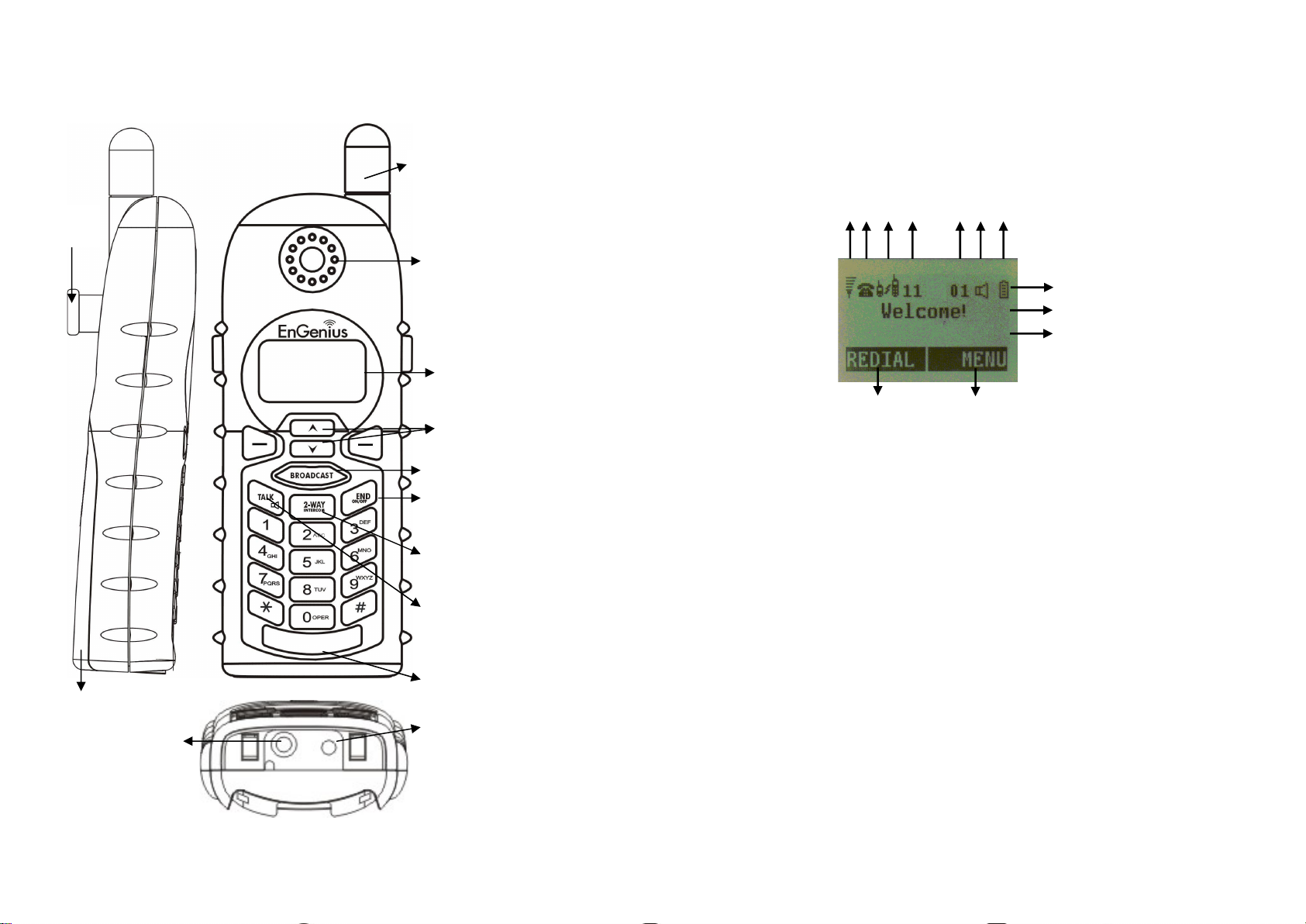
Handset Illustration
Antenna
Travel charger jack
Battery
cover
4-line LCD
TALK/FLASH/
Microphone
KEYLOCK/
1. 4-line LCD (Liquid Crystal Display)
a.
The L
CD display has LED (Light Emitting Diode) for backlighting.
b. The 1
st
line of LCD consists of icons.
c. Icons explanation from left to right
radio signal strength received.
Indicates if phone line mode is active
Indicates if Intercom mode is active
Displays a handset icon and a 2
-
digit Handset ID
logs , text messages or phonebook
handset.
Indicates if speaker phone is active
(1) (2) (3) (4) (5,6) (7)
(8)
e
e
d
d
b,c
Handset Features
Basic Handset Features
Belt Clip
Holder
Receiver
Volume control /
Scrolling
Broadcast key
END & Power
ON/OFF key
2-WAY/ INTERCOM
(For PRO)
(For Walkie)
(1)
◎ (2) Call in-progress (ON/OFF-Hook)
(3)
(4)
◎ (5)
RSSI (Receive Signal Strength Indicator)
During a call, the number of bars is proportional to the
Intercom in-progress
Handset ID
Two-Digit Address Index
Shows address index when viewing contents of the call
Headset jack
(2.5mm)
13
◎ (6)
(7)
(8)
Line Indicator
Indicates the number of the line being accessed by the
Speaker phone
Battery Strength
Number of bars is proportional to the amount of battery
time remaining.
14
Page 8

Indicates charging when in charger cradle.
alphanumerical characters.
e. The last line displays the left and right soft keys.
Re: There is only right soft key in idle mode of DuraWalkie.
Not
e:”◎”means only shown on DuraFon PRO handset.
2. Ringer
a. Rings to an incoming call.
b. Distinctive alert sounds indicating va
rious events:
(1) Single Beep: successful key entry
indicates power on/off
low battery
warning
indicates a call is on
-
hold
a.
Places or answers a telephone or intercom call
local phone companies during a call.
speakerphone
a.
In Idle mode, press to
lock up the keypad
a.
Places an intercom call to another handset ID or a group ID.
without the assistance from the base.
Half duplex broadcasting to handsets for immediate announcement
Make menu selection.
a.
Scroll through records and menu selections.
b.
Adjust receiver voice volume when in Talk mode.
b.
Leaves current menu opera
tion, up one level.
c. Press for 3 seconds to off the power
1. Multiple handsets registration
as greeting message and other base administrative functions.
DuraWalkie handsets.
2.
Ringer / Vibrator
vibrate
-
and-ring/ off)
3.
Caller ID
(For DuraFon PRO
only
)
Caller ID
service from local telephone company)
d. The 2nd and 3rd lines of the LCD, maximum 14 characters each,
display status, message, menu selections, or user-editable
6.
BROADCAST(
7.
Left/Right Soft Keys(
8.
Up( ) /Down( ) Scrolling Keys
)
)
(2) Double beep: failed operation or invalid key entry, also
(3) Periodic 1-Long-2-Short Beep (repeat every 10 seconds):
(4) Periodic 1-Long-2-Short Beeps (repeat every 30 seconds):
3.
TALK/FLASH/( )(For DuraFon PRO only)
b. Sends a Flash signal to phone line to retrieve a dial tone after
the call ends, or to perform the call waiting feature provided by
c. Press and hold the key for one second to enable/disable
4.
KEYLOCK/( )(For DuraWalkie only)
b.
5.
b. Intercom calls are digital, full duplex, and are conducted
In 2-Way/Intercom mode, press and hold key to
enable/disable speakerphone.
2-WAY/INTERCOM(
)
9.
END; On/Off Key(
a.
Ends a call.
)
Additional Handset Features
a.
b. ID 10 and 11 are the first two ID’s assigned by the base and are
Note: Unless necessary, it is better not to assign ID 10 and 11 to
c.
a. Six ringer volume selections (high/ medium/ low/ vibrate/
b.
Up to 90 handsets.
designated “administrators” who can change base settings such
ID 01-07: Group IDs. Handsets can “subscribe” from the
handset menu to group(s) and be paged when a landline caller
or an intercom caller enters a Group ID.
Four ringer type selections
c.
Press and hold key for one second to enable/disable
speakerphone.
15
Displays incoming call phone number and name on the LCD (needs
16
Page 9

Re:
through the analog ports
. 4.
Call Waiting
with Caller ID
(For DuraFon PRO
only
)
local telephone company)
through the analog ports
.
5.
Name Tagging
with Caller ID
(For DuraFon PRO
only
)
telephone company)
through the analog ports
. 6.
DND (Do Not Disturb, i.e., Silent Ring)
Silences the incoming call ring for current call only.
7. Three Ca
ll Logs
(For DuraFon PRO
only
)
numbers.
local telephone company.
local teleph
one company.
in display.
through the analog ports
. 8. Key-
guard
9. Dialing Prefix
(For DuraFon PRO
only
)
dialing.
10. Call Hold
(For DuraFon PRO
only
) a.
Places call on hold
b. Battery Hot Swap: Change battery
while call is on hold.
11. Mute
12. Phonebook
28-digit) and name (up to14
-
character)
b. Alphabetically sorted display and searched by letter
c. Dial from display
e.
Phone book transfer via air
registered handsets
handsets
Re:For DuraWalkie, it can only store 2
-
digit hands
et ID(or Group ID).
13. Key Tone
a. Three key
-
tone volume selections (high/low/off)
b. Four key
-
tone type selections
14. Call Timer
(For DuraFon PRO
only
)
immediate
ly after the call
without announcement.
Displays 2nd incoming call information on the same phone line when
If behind a PBX or Key system, Caller ID information will only
be recognized if the PBX or Key system passes that information
1st call is in progress (needs Call Waiting with Caller ID service from
Up to 14 digits, including pause(s), one access code can be pre-
programmed to be added automatically in front of the dialed
number when dialing from call logs, phonebook, and dial-and-send
Re:
Matches the Caller ID with the phone book entries; once matched,
Re:
a. Called Log: Stores 10 phone numbers (up to 28 digits each)
b. Received Call Log: 10 entries (14-digit phone number, 14-
c. Missed Call Log: 10 entries (14-digit phone number, 14-
If behind a PBX or Key system, Caller ID information will only
be recognized if the PBX or Key system passes that information
the LCD screen will display the name or nickname instead of pure
Caller ID info (needs Call Waiting with Caller ID service from local
If behind a PBX or Key system, Caller ID information will only
be recognized if the PBX or Key system passes that information
dialed most recently. Can perform last-number redial on all 10
character names, and time stamp), needs Caller ID service from
character names, and time stamp), needs Caller ID service from
a. 90 entries, each stores a phone number or handset ID (up to
d.
i. Transfer specific phonebook to one handset or all
ii. Transfer all phonebooks to one handset or all registered
a. Display call time duration for current call during and
During the stand-by mode, you can enter the phonebook by
pressing or scrolling key
d. Phone numbers and names can be saved into phonebook while
Re:
If behind a PBX or Key system, Caller ID information will only
be recognized if the PBX or Key system passes that information
17
Call Transfer
15.
a. Direct Transfer: transfer a telephone call to another handset
b.
Announced Transfer: speak to the destination handset before
transferring a telephone call.
18
Page 10
16.
19.
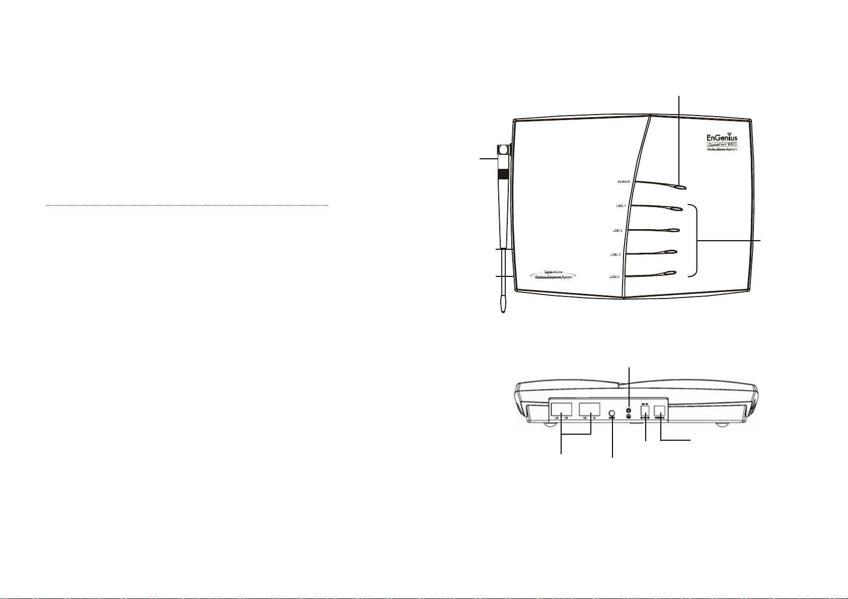
Power LED
Line Status
Reset Button
REG Button
Antenna
Line 1 ~ 4
AUDIO IN
DC IN
CONSOLE
GROUNDING
SCREW
Call Conferencing(For DuraFon PRO only)
a.
2-handset and 1-line conferencing (Applied for DuraWalkie
too).
b.
17.
1-handset and 2-line conferencing.
Line Selection (For DuraFon PRO only)
When enabled from the handset menu, a handset user will be
prompted to select from a list of available lines before making an
outgoing call.
18.
a.
b.
PBX option transfer(For DuraFon PRO only)
PBX transfer via air
Transfer specific PBX option to one handset or all registered
handsets
c.
Transfer all PBX options to one handset or all registered
handsets
Base Selection(For DuraFon PRO only)
When enable from the handset menu, a handset user can manually
select the base which is the nearest one with user before making an
outgoing call.
Repeater Operation
20.
In order to get better range performance for handset to handset
calls(intercom and broadcast), install a repeater and make the calls
via repeater is able to extend the range of handset to handset calls.
Base Illustration
Base Features
LEDs
19
20
Page 11

1. Antenna
installation may damage the connector
station itself) as high as possible for a clear transmission path.
2. Audio
-
in Jack
(3.5mm)
3. Line Status LED
Indicates an active telephone line.
4. Power
LED
Indicates base station has power.
5.
L1 – L4 Standard RJ
-
11C/CA
-
11A connector to plug in the telephone line
6. DC In
Jack
Jack for AC power adapt
er
compatible AC, in case any damage or safety issue.
7. Registration
Key (REG)
8.
Reset Button
a. Restores base station to factory settings
b. Reset button is indented to prevent accidental system reset.
re-registered after a base station reset.
9. Grounding
screw
Connecting with grounding
wire
10. Console jack
Jack for firmware upgrade (Type
-
B USB connector)
Re: Please consult with EnGenius Tech support
about the firmware upgrade.
simultaneous incoming calls.
group paging to a group of handsets (with Group ID).
d.
1. Supports both DTMF and Pulse dialing(For DuraFon PRO
only)
enter base ID(00
–
07)- 1 to select Tone or Pulse dialing mode.
b. Default is
Tone dialing.
2. Administrator programmable Flash key timing(For DuraFon PRO
only)
select flash key timing
b. 9-level (100 ms
- 900 ms) timing selections, default=
6
00 ms
.
the new value will work.
3.
Call Transfer
to PBX Extension(For DuraFon PRO
only)
program the feature code of call transfer function.
b. Need to adjust the Flash time to match your PBX setting.
reset (reset the base and re
-
register all handsets).
Basic Base Station Features
a. The antenna port has a reverse thread connector; to remove antenna or
cable, turn clockwise; to install, turn counterclockwise. Improper
Additional Base Station Features
4-channel Auto-Attendant
1.
a.
b. Allows private paging to a single handset (with individual Handset ID) or
4 Auto-Attendant can be active at the same time in case of 4
b. When using an outdoor antenna, locate the antenna (not the base
Re:The AC power adapter is 100~240VAC/12VDC, do not use other non-
Enters registration mode along with handset, assigns handset ID (10-90).
c. All handsets (including administrator) and additional base(s) need to be
c.
e.
2.
Per line AA enable/disable by administrator. When disabled for a line,
the administrator can set all handsets to ring with an incoming call on
that line, or a particular Handset/Group ID (either one; not
simultaneously) can be assigned to have incoming call privileges on that
line. See AA Configuration by Administrator
Up to 120 seconds customizable main greeting message.
Default of 4 lines AA is OFF.
Optional Outdoor Antenna Kit with cable.
Administrator Features
Handsets 10 and 11 are designated administrators. Both have the same authority to
perform base station administrative functions from their handset menu selections. No
password is required.
a. From an administrator handset (Handset 10 or 11 ), press MENU- 9 – 1 –
a. From an administrator handset (Handset 10 or 11), press MENU- 9 -1-2 to
c. The default value (600 ms) works in most areas. Changing this setting may
result in Flash function not working. Change only when you are certain
21
a. When the DuraFon PRO is installed behind a PBX system, you can pre-
Re: If loosing administrator handsets (handset 10 and 11), all settings must be
22
Page 12
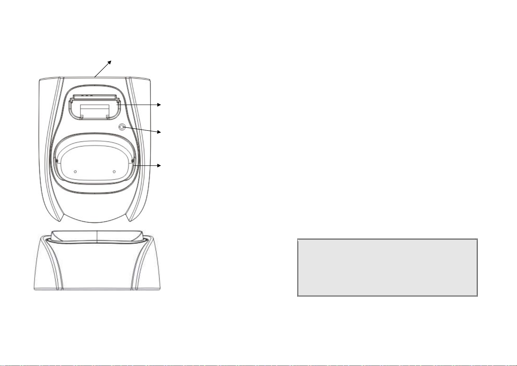
Charger Illustration
DC In
Handset Charging Slot
1. DC In
Connects to Charger AC Adaptor.
2. Handset Charging Slot
a. Charge
handset battery
when handset is placed in cradle.
b. Refer to the handset LCD for charging status
(1) Charging: LCD screen showed “Charging”
woul
d display “Fully Charged”
screen would display “Charge Fail”
3. Spare Battery Charging Slot
a. Charge spare battery
when batt
ery is placed in slot.
b. LED as the spare battery
charging indicator
(1) Slot is empty and the power is on: LED is Green light
(2) Charging: LED is Orange light
(3) Fully Charged: LED returns to Green light
4. It is impos
sible to overcharge the battery
using this charger.
on the LCD display.
Charger Features
Spare Battery Charging
Slot
Spare Battery Charging
Indicator
(2) Fully Charged: battery status bar stands still and the LCD screen
(3) Charge Fail: Should an error occur during charging mode, the LCD
5. The adaptor for charging station can be used as travel charger as well.
However, you cannot turn off the power while charging with the travel
charger. A Warning message: “Unplug Travel Chgr then OFF” will be shown
Notes:
I. Fully charge battery packs before first use.
II. Both handset and spare batteries can be charged at the same time.
III. Handset will be “power on” automatically when placing on the
charging slot.
IV. However, if you run down the battery, it will take around one
minute for handset to auto power on.
23
24
Page 13

Optional DuraFon PRO Platform Products
1. DuraWalkie handset
EnGenius DuraWalkie is an optional digital two-way radio
only handset compatible with DuraFon PRO, it can be
registered to PRO base as an optional handset. The
DuraWalkie handset can broadcast, intercom and even
receive a call transferred to it by a PRO full-featured handset.
Please contact EnGenius for the detail specifications and
features.
2. DuraFon UHF handset
EnGenius DuraFon UHF is an optional dual-mode handset
compatible with DuraFon PRO and can be registered to
PRO base. The DuraFon UHF handset offer telephone,
digital 900 MHz two-way radio as-well-as analog UHF twoway functions. Please contact with EnGenius for the detail
specifications and features of the DuraFon UHF handset.
3. DuraFon PSL
4.DuraFon USL
EnGenius DuraFon USL is an optional single-line
system compatible with DuraFon PRO, it can be
registered to PRO base as a slave single line
extension. Please contact with EnGenius for the
detail specifications and features of the
DuraFon PSL.
EnGenius DuraFon PSL is an optional single-line
system compatible with DuraFon PRO, it can be
registered to PRO base as a slave single line
extension. Please contact with EnGenius for the
detail specifications and features of the DuraFon
PSL.
25
26
Page 14

fax machine, answer machine, cordless phone, etc.)
1. Install base station antenna.
clockwise. Improper installation may damage the connector.
jack on the back of the base station.
DC In jack.
should be plugged into a surge protector with phone line protection.
phone jacks in random order.
mm) end into the MOH jack on back of the base.
6.
To ground the grounding wi
re
b.
Insert the grounding wire
(enclosed in the box)
. c.
Tighten the screw.
d. Connect the grounding wire to the ground.
event of a lightning strike.
Multi
-
base setups
:
capacity.
(about 30 feet) between any
two base
stations.
Expanding coverage
:
Re : when a call is coming in from L1, all handsets can pick up the
Legacy
Base-1 Base-2 Base-3
4
Base Station Installation
For best performance, maintain a distance of at least 1 meter (about 3 feet)
between the base station and other electronic devices (e.g., TV, computer, stereo,
The base station’s antenna port has a reverse-thread connector; to
install antenna or cable, turn counter-clockwise; to remove, turn
2. Plug the transformer end of the base station AC/DC adaptor into a
standard AC electrical power outlet, plug the other end into the “DC In”
a. The base adaptor’s DC plug is larger in dimension than the charger’s
DC plug. The charger adaptor’s DC plug will not fit into the base’s
b. The base station’s power supply (DC Adaptor) and telephone line
Re: Proper grounding is very important to protect the base station from
the external noise and to reduce the risk of electrocution in the
Notes:
Recommended phone line features from the local phone company:
Multiple phone lines “hunt group” is a useful feature and works well with
this phone system. This feature “ties” multiple phone lines to a single
phone number. When an outside caller calls this common phone number,
the phone company automatically finds a free line. In a hunt group, the
Call Waiting and the Caller ID with Call Waiting (or called Type II Caller ID)
features are unnecessary because a 2nd call will come in on a separate line,
rather than on the same line. For a 2nd call coming in on a separate line,
the phone system’s built-in Call Waiting feature will alert the user and
allow the user to toggle between 2 lines.
EnGenius DuraFon PRO has the capability to expand the coverage or
Re: For best performance, maintain a distance of at least 10 meters
3. Plug one end of the phone cord into one of the 4 phone jacks marked L1
~ L4 and plug the other end into the telephone outlet. Since DuraFon
PRO has the built-in “line detection” feature, it is okay to plug in the
Connect an external telephone answering device by following the
4.
instructions that come with the answering device. An exemplary
configuration: install the external answering device in-between the wall
phone jack(s) and the Base Station. Either a multiple of single-line
answering devices or a multiple-line answering device can be used.
5. To use the Music/Message-On-Hold feature: Connect one end of a
standard audio cable into a radio or audio player, and plug the other (3.5
a.
Loosen the screw of grounding jack ( ) on the rear of base.
27
Parallel connects all L1/L2/L3/L4 in each base as below schematic(up
to 8 bases), the use coverage will be several times increased.
Note: Telephone calls cannot be handed off between base units.
PBX
1
2 3 4
1 2 3
1 2 3 4
28
Page 15

call, as long as the handsets are in the coverage of base1~3.
setting mode
registration process)
c. Repeat, as needed, to add handsets
adding additional base units.
2. Establishing additional Base Units:
a. Press REG button on new Base.
b. Use Handset 10 or 11 to Add base :
Press
M
ENU 8 1 c.
Enter 01~07 (base ID)
d. Repeat, as needed,
to add base units
Expanding capacity
CANCEL
PBX
Base-2 Base-3
4
setting mode
registration process)
c. Repeat, as needed, to add handsets
2.
Establishing additional Base Units:
a. Press REG button on new Base.
b. Use Handset
10 or 11 to Add base :
Press
M
ENU 8 1 Enter 01~07 (base ID)
c.
Repeat, as needed, to add base units
the Charger.
2. Install battery
pack onto the handset.
3. Install handset antenna.
4. Place handset onto the charger front slot.
CANCEL
1. Handset Registration.
a. Press REG button on Base 00(default), four LEDs will light up in
b. Handset operation: Press MENU 6 1 . (It will complete the
Re : Handsets can answer calls from any port or line, unless port is dedicated to
a specific handset or group.
1. Handset Registration.
a. Press REG button on Base 00(default), four LEDs will light up in
Note: Additional handsets should be added to the system before
10
Select Mode:
1. Add Base
10
Added Base
Number : **
Notes:
1. Only Handset 10, 11 can assign Base ID.
2. Base 00 is a primary base. All handsets must register only on Base 00.
User capacity can be increased by adding additional base units.
Up to 8 base units can be supported.
Legacy
1
2 3 4
1 2 3
1 2 3 4
Base-1
b. Handset operation: Press MENU 6 1 . (It will complete the
10
Select Mode:
1. Add Base
10
Added Base
Number : **
Notes:
1. Only Handset 10, 11 can assign Base ID.
2. Base 00 is a primary base. All handset must register only on Base 00.
3. To avoid interference, the interval between any two bases should be
at least 10 meters.
Handset and Charger Installation
1. Plug the transformer end of the Charger AC/DC adaptor into a standard AC
electric power outlet, plug the other end into the “DC In” jack on the back of
29
30
Page 16

5. The phone system is now ready to perform basic functions such as making and
programming is needed for basic operations.
not included, but can be purchased from a local home center.
keys are active in IDLE mode.
light up respectively.
entered. Four LEDs will light up in Registration
mode.
1. IDLE mode
- this is the default mode.
into SLEEP/IDLE mode
to save battery
power.
END key for 3 seconds.
c. The idle screen display (custom name) can be edited.
d. The 2
-
digit number represents the handset ID.
2. M
ENU mode
a. Press the Right soft function key to
activate MENU mode
.
contained in memory can be changed.
covered in greater detail from page 52.
d. T
he MENU structure display as below:
receiving phone calls and intercom calls. No base station or handset
6. Charging cradle may be wall mounted, but an “L” bracket should be used for
support under the cradle to avoid breaking mounting slots. An “L” bracket is
Note:
1. The handset packaged along with a Base Station is preregistered at the factory. If you have a new handset, you will
need to register the handset with the base station in order to
be recognized as a member handset by the base and by other
handsets. See Handset Registration.
2. Fully charge battery packs before the first usage.
Basic Operations
Operation Modes
Both the base station and handset have levels of operation at which time only certain
procedures of functions can be performed.
Re:The main difference between DuraFon PRO and DuraWalkie is the handset of DuraFon
PRO has the capability to make telephone calls, and the handset of DuraWalkie does
not.
A. Base Operation Modes
1. IDLE mode- this is the default mode. The intercom, broadcast, and volume
2. TALK mode- the base operates in this mode during a phone call, intercom use,
and broadcast operation. The “In Use”, “Intercom”, and “Broadcast” LED will
3. REGISTRATION mode- the base enters this mode by pressing the REG button
for three seconds. There are no active base unit keys once this mode has been
B. Handset Operation Modes
31
a. If there is no on-going activity, the handset automatically goes
b. The handset can be turned off completely by holding down the
b. In MENU mode, the handset settings and information
c. The functions available through the MENU selection are
32
Page 17

1.KeyGuard
2.PhoneBook
1.Diale
d
1.Ring Volume
1.Dial Prefix
6.Registration
7.BC/INT Type
5.Settings
4.Sound
3.Call Logs
9.Admin
8.Multi
-Base
Select Mode:
Admin:
1.
Register
P2P Mode
Main menu
Sub-menu
1.KeyGuard
2.PhoneBook
1.Ring Volume
1.Group Select
5.
Settings
6.
Registration
4.Sound
3.
Unused
9
.Admin
7.BC/INT Type
Select Mode:
Admin:
8.Multi
-Base
1.
Register
P2P Mode
Menu Tree
DuraFon PRO
Main menu Sub-menu
2.Received
3.Missed
2.Ring Tone
3.Key Volume
4.Key Tone
2.Group Select
3.Base Select
4.Clear
5.Naming
6.Contrast
7.Backlight
8.Line Select
9.PBX Options
0.Language
#.PA On/Off
*.Name Tag
DuraWalkie
2.Ring Tone
3.Key Volume
4.Key Tone
2.Clear
3.Naming
4.Contrast
5.Backlight
6.Language
#.PA On/Off
33
2.Deregister
3.Remote REG
Repeater Mode
1.Add Base
1.System
2.Line Setting
3.Auto Attndnt
2.Deregister
3.Remote REG
Repeater Mode
1.Add Base
1.System
2.Line Setting
3.Auto Attndnt
34
Page 18

Making a Telephone Call (For DuraFon PRO only)
“Clear” erases the entire line but remains in the dialing mode.
3. Speed dial
by access the entries in the phone book
1. Broadcasting all handsets
to all handsets within communication coverage
c.
Begin speaking after the series of beeps has ended.
2. Broadcasting a group of handsets
all handsets within communication coverage
c. Begin speaking after the series of beeps has ended.
3. Broadcasting an individual handset
all handsets within communication coverage
c. Begin speaking after the series of beeps has ended.
1.
Press , wait for dial tone, and then enter phone number.
2.
Alternatively, you can enter phone number first then press key.
When using this method, you can use the CLEAR (Left) and DELETE (Right) soft
keys to edit the number entered. “Delete” erases the last digit entered.
a.
b.
4.
Press or scrolling key to enter the phone book
Press to dial the number.
To abort dialing, press key.
2.
Press key to end the call.
3.
During the call, press and hold the key, the speakerphone is
active.
Notes:
1. Intercom calls can be made regardless if the Base Station is present.
2. If a Group ID is entered, the first handset (belonging to that group)
that answers will establish a link with the caller. See Handset Group
Subscription.
3. If a link cannot be established, the LCD shows “No Connection” after
a 12-second time out.
Making a Broadcast
5.
During the call, press and hold the key to activate the
speakerphone.
Notes:
1. After a link is established, the Base ID will appear on the upper-right
corner. If no Base ID shows up, it implies that you are approaching the
boundary of the coverage.
2. If the line is occupied, the LCD shows “No Line Available” and handset
returns to standby mode.
3. If a link cannot be established, the LCD will show “No Base” after a 12-
second time out.
4. A call duration timer will start displaying the length of the call after link is
established.
Making a 2-Way/ Intercom Call
The EnGenius Industrial Cordless Phone System offers private, Intercom/ 2-way radio calls
independent of the base station. Intercom/ 2-way communication can be placed from
handset to handset.
Handset to Handset Calls
1.
Press key followed by a two-digit handset ID or Group ID.
35
a.
b. A series of beeps will indicate initiation of handset broadcast
d.
a.
b. A series of beeps will indicate initiation of handset broadcast to
d.
a.
b. A series of beeps will indicate initiation of handset broadcast to
d.
Press & hold key from one handset
Release key to end the broadcasting
Enter the Group ID and then press & hold key
Release key to end the broadcasting
Enter the Handset ID and then press & hold key
Release key to end the broadcasting
36
Page 19

Notes:
1. Press
REDIAL
(Left) soft key.
has been turned off.
1. Voice volume can only be adjusted during a call.
1. You need to continuously press key when doing broadcast. The
broadcast will be over once user release the key.
2. You need to notice that there is no bi-bi-beep sound when receiving a
broadcast.
3. You can press the SILENT (Left) soft key if you choose to ignore the call. The
SILENT key operation is valid only for the current call. You can silent all
broadcast by turning off the ringer to set auto-silence from the handset menu.
Redial (For DuraFon PRO only)
The LCD shows the last phone number dialed. To dial this number, press DIAL
2.
(Left) soft key.
3.
Use or Key to scroll through the last 10 phone numbers dialed.
Select and press DIAL key.
Note: Intercom numbers (Handset ID) are not stored in the last 10 numbers
dialed log.
Receiving a Telephone Call (For DuraFon PRO only)
1. When an incoming call arrives, the handset will ring or vibrate unless the ringer
2. If the handset is on the charger cradle (ringer will be temporarily switched to
“Ring” if it has been set to “Vibrate”), lift the handset then press the key
to start the conversation.
3.
If the handset is not on the cradle, press any key (except , and the SILENT
soft key) to answer.
4.
During the call, press and hold the key, the speakerphone is active.
Notes:
1. You can press SILENT (Left) soft key if you choose to ignore the call.
Unlike turning off the ringer (from the handset menu), the SILENT
key operation is valid only for the current call.
2. If Caller ID service is available, the LCD will display the incoming call
information. If the LCD shows “Private” or “Unknown”, the caller’s
information may have been blocked by the caller or the originating
phone company.
Receiving an Intercom Call
When an intercom call arrives, the handset will ring or vibrate unless
1.
the ringer has been turned off. Press to answer the intercom
call.
If the handset is on the charger cradle (ringer will be temporarily
2.
switched to “Ring” if it has been set to “Vibrate”), lift the handset
and press key to answer intercom call.
3.
If the handset is not on the cradle, press
4.
During the call, press and hold the key, the speakerphone is
active.
Notes:
1. The LCD displays the caller’s Handset ID.
2. You can press the SILENT if you choose to ignore the call. Unlike
turning off the ringer the SILENT key operation is valid only for
the current call.
key to answer.
Ending a Call
To end a telephone or intercom call, press key or place handset into
charging cradle.
Adjusting Receiver (Earpiece) Voice Volume
37
38
Page 20

There are 6 levels of volume selections. Default as volume 3. Use
3.
The new setting remains effective for all future calls until changed.
HOLD
(Right) soft key.
press
0 to mute the handset microphone.
When mute is active, the other party will
you can still hear the other party.
unmute the handset microphone.
Re: If established an intercom call, when
end the mute, press
UNMUTE
(Left) soft key.
the ringer until it is
turned
on again from the menu
.
locked. No key entry is accepted except the power on/off key.
3.
Key Guard
is in effect until un
locked or powered off.
soft key to enter the call logs information.
2.
and scrolling key to adjust.
Placing a Call On Hold (For DuraFon PRO only)
1. When a call is in progress, it can be put on hold by pressing the
To return to the conversation, press “UNHOLD”
2.
Notes:
1. The call being placed on hold can only be removed from HOLD by the
handset that puts it on hold.
2. Handset LCD displays a call is being on hold. An alert tone (double
beep) every 30 seconds will remind the handset that a call is being on
hold.
3. If the operation (e.g., call transfer) after putting a call on-hold fails, the
held call may be dropped.
4. You can power off the handset (e.g., change battery) while call is on
hold. After power on again, you can continue the call by pressing
UNHOLD (Left) soft key or select “3” from the Option menu to
terminate the hold state.
5. You can only unhold the call when within the coverage area of the
base. Once you’re out of the base coverage, you can return to standby using “Clear hold” function in the OPTION list item #3.
Mute
1. After a link is established, you can press OPTION (Left) soft key and
2.
3. To end the mute, press OPTION (Left) soft key and press 0 to
not hear your voice, but
Do Not Disturb (Silent Ring)
1. Enter the key sequence MENU 4.Sounds 1.Ring Volume, then
select “Off”. Press SAVE to confirm your choice. This will turn off
For temporary silencing the ringer when an incoming call arrives,
2.
press SILENT (Left) soft key.
Key Guard
1. To prevent accidental dialing, you can press MENU (Right) soft key,
then press 1 to select KeyGuard option. The handset keypad is
To unlock the keypad, press UNLOCK (Left) soft key, then, within 2
2.
seconds, press the digit “1” to unlock.
To View Missed Call(s) (For DuraFon PRO only)
1. Whenever you have missed incoming call(s), you can press VIEW
You need to subscribe the caller ID service from local telephone
2.
company to retrieve this data.
To Call back from Call Log (For DuraFon PRO only)
When you review missed incoming call(s), you can directly call back
1.
by pressing key.
39
40
Page 21

2. The displayed CID number in most cases will be a 10-digit number
follow below rule to adjust the calling back number:
a. Press
FORMA
T key once, the 3
-
digit area code will be removed.
displayed number.
displayed number.
digit
–
> 11-digit
–
> 10-digit in
circle.
1. Charge the battery
when one or several of the following happen:
a. Phone beeps twice every two seconds.
b. Battery icon is empty.
c. Phone does not respond when a key is pressed.
d. LCD and backlighting become dim.
e. A decrease in coverage is experienced.
manufacturer provided battery
and charger!
with the base station at the factory.
same Handset ID.
3. Registrat
ion: a. Press MENU
-
6 to enter the registration mode
indicating successful registration.
d. Repeat above steps for all additional handsets.
which gives them administrator privileges.
Re : Base 00 is a primary base. All handse
ts m
ust register
to Base
00.
4. De-registration
:
for future registration.
handsets.
menu.
LED come on
f. Press the handset number key
2 , this completes the de
-
registration
with the 3-digit area code followed by the 7-digit telephone
number. If the area code is unnecessary for calling back, you can
b. Press FORMAT key twice, “1” will be added in front of the
Advanced Operations
Handset Registration
1. If your handset is purchased as part of a system, it has been pre-registered
c. Press FORMAT key three times, it will loop back original
Re:The CID default is 10 digits, when press FORMAT key, it will be 7-
3.
After the displayed number chosen, press the key to call back.
Battery Recharge and Replacement
You can replace the handset battery after placing the call-in-progress on hold.
2.
3. Battery talk time and standby time vary depending on the talk/standby pattern
and the operating distance. Returning the handset back to the charging cradle
as often as possible is recommended for best performance. Use only
2. If the Handset ID reads “00,” that means it is a new handset or the ID has been
erased. You need to register the handset with the base station. In certain
situations, you may want to change a handset’s ID. For example, you want to
change a particular handset from a user to an administrator (ID 10 or 11), or
vice versa. Or in some rare occasions, you find another handset having the
b.
c. Press handset key “1”, this completes the registration process.
e. The first two handsets registered will be given ID 10 and 11,
a. You can de-register a handset from a base. De-registration will reset the
b. After deregistration, the handset will not be able to use the base to make
Press and hold the base’s Registration (REG) button for 2
seconds until the L1, L2, L3, and L4 LED come on.
The base station will assign a handset ID between 10 and 99.
The assigned ID will be displayed on the handset LCD,
Handset ID to 00, erase the system security code, and free up the old ID
or receive phone calls, nor can it use the intercom to reach other
41
c.
d. Press the handset number key 6 , this will enter the handset registration
e. Press and hold the base’s REG button for 2 seconds until L1, L2, L3, and L4
Press handset MENU (Right) soft key.
42
Page 22

process. Upon successful de
-
registration, the handset will show ID “00”.
handsets (ID 10 and 11) only.
range o
f the base station.
b. Press administrator handset
MENU
(Right) soft key
menu.
d. Press number
1
, handset enters system setting menu.
cleared.
otherwise it will show “Message not received, try again”.
next ID assignment should be.
menu.
d. Press number
1
, handset enters system setting menu.
assigned next by the base.
otherwise it will show “Message not received, try again.”
vacate by de
-
registering with the base.
another handset.
can perform remote registration
. b.
Press administrator handset
MENU
(Right) soft key
c. Press the number
6 ,
this will enter registration mode
.
on. e. Proceeding the handset registration process for new handsets.
which group(s) they want to be in.
calls. Then handset 11 will need to “subscribe” to Group 2 and Group 3.
3. Group Selections:
a. Press handset
M
ENU 5 to enter the handset setting me
nu b.
Press number
2 , handset enters group select menu.
Notes:
1. The base has a 30 second registration timeout starting from pressing
the REG button. The handset has a 12 second registration timeout
starting from the time registration or de-registration option has been
selected. The base and handset will automatically exit registration
mode after timeout.
2. Repeat registration or de-registration process if unsuccessful.
Advanced Registration:
1. Advanced registration functions can be performed by administrator
f. Upon successful operation, the handset LCD will display “Done,”
g. If the handset ID is already in use by another handset, the
administrator will be alerted. In that case, the administrator can
choose another ID or asks the handset having the desired ID to
h. Perform registration immediately afterward for the handset
desiring a specific ID to ensure that the ID is not taken by
Remotely register Handset :
5.
a. If base install in ceil or higher location, administrator handsets
Administrator handsets can perform advanced registration function
2.
as long as it is within range with the base station. The base station
does not need to be in registration mode.
De-register a Handset ID by administrator:
3.
a. Make sure that the administrator handset is within the coverage
c. Press the number 9 , this will enter the handset administration
e. Press number 4 , and enter the two-digit Handset ID to be
f. Upon successful operation, the handset LCD will display “Done”,
Obtain a Specific Handset ID:
4.
a. If a particular Handset ID is preferred over sequentially assigned
ID, the administrator can “tell” the base in advance what the
b.
c. Press the number 9 , this will enter the handset administration
Press administrator handset MENU (Right) soft key.
d. Press number 3 , this will replace the procedures to press &
hold the base REG button until the L1, L2, L3 and L4 LED come
Notes:
1. De-registration by the administrator will disable a handset’s ability to use the base
station to make or receive phone calls. This also frees up the ID for future
registration.
2. Handsets de-registered by the administrator can still perform intercom to other
handsets.
Handset Group Subscription
1. Up to nine handset groups (01-07) can be defined and handsets can decide
2. For example, Group 1 represents the Customer Service Group, Group 2
represents the Sales Group, and Group 3 is the Marketing Group. Suppose that
Handset 11 wants to receive incoming rings for all Sales and Marketing related
e. Press number 5 , and enter the two-digit Handset ID to be
43
44
Page 23

c. Press ADD soft key and enter two-digit group number (01~07)
to add membership in a group.
d. Repeat for all desired groups.
enter group number.
transfer the call.
2. Press
HOLD
soft key to put call on hold.
3.
Press
OPTION
soft key to enter feature list for selection.
handset extension.
a. Un-
announced Call Transfer
:
automatically transferred to the destination h
andset.
b.
Announced Call Transfer
:
conference.
another handset extension.
key.
connected.
5.
phone line.
b. After the second line answers, press the
CONF
(Left) soft key.
simultaneously.
1.
e. Delete group selections by pressing DELETE (Right) soft key and
Notes:
1. The handset can change group affiliations at any time.
2. The base (administrator) is not responsible for group assignments.
Consequently, it cannot unsubscribe a handset from a group.
Call Transfer (For DuraFon PRO only)
1. While a telephone call is in progress, you can place the call on hold and
4. Press number 2 and enter a two-digit Handset ID to call another
1. While a telephone call is in progress, you can place call on hold
and bring in another phone line or another handset for a 3-way
Press HOLD (Right) soft key to put the current call on hold.
2.
Press OPTION (Right) soft key to enter selection menu.
3.
3-Way Conferencing with a Second Handset:
4.
a. Press number 2 and enter a two-digit Handset ID to call
b. After the second handset answers, press the CONF (Left) soft
c. Two handsets and one phone line can now talk
simultaneously. Any one party can drop out of the 3-way
conferencing, leaving the remaining two parties still
3-Way Conferencing with a Second Phone Line:
a. Press number 1 and enter a phone number to call another
Press END before the destination handset answers, the call is
(1) Speak to the destination handset.
(2) Press XFER soft key or the END to end announcement. The call is
transferred to the destination handset.
Notes:
1. If the destination handset does not answer after handset paging
timeout, the call is routed back to the originating handset.
2. Above described “Call Transfer” is for DuraFon PRO handset-to handset
call transfers.
3-Way Conferencing (For DuraFon PRO)
45
c. One handset and two phone lines can now talk
Notes:
1. 3-way conferencing between 3 handsets is not supported.
2. Unlike 3-way conferencing provided by the phone company, 3-way conferencing
I. If one phone line hangs up, the handset continues
talking to the remaining phone line.
II. If the handset presses key, the 2nd phone line will
be dropped. The handset and the first phone line
continue conversation.
involving 2 phone lines will take up two physical lines, leaving only two lines left
available for other handsets. The handset must have access to a second line.
Base Select (For DuraFon PRO only)
A handset can manually select the desired base station before
46
Page 24

access outbound line.
greet a telephone line incoming call.
extension number (Handset ID) or press for operator
designated as the operator is also user programmabl
e.
number or press for the operator”
b. Default operator: Handset 10
.
Press handset MENU (Right) soft key.
2.
Press the number 5 , this will enter the handset setting menu.
3.
Press number 3 , handset enters Base Select setting mode.
4.
5
Use or arrow to scroll up and down the selection
on/Off.
Make a selection (default =off), and press SAVE (Left soft key).
6.
Re: When turns on the Base Select, you must enter 2-digit Base ID
after press key.
Notes:
1. Because this setting allows handset manually select the base station, the handset
must be in range with the direct base station.
Call Waiting (For DuraFon PRO only)
1. A handset, while talking on one phone line, can be informed of the arrival of a new
incoming phone call.
2. For example, suppose that Handset 15 is talking on Line 1. When a new call comes in
on, Line 4, and the caller enters extension number “15” when prompted by the AA,
or if the call is set to be routed to Handset 15 when AA is disabled.
3. The base station recognizes that Handset 15 is busy. Instead of announcing to Line 4
that Handset 15 is busy, the base sends an alert to Handset 15.
4. Upon receiving the alert, the handset sounds an audible double beep alert and LCD
displays “New call on Line 4”.
5. Handset 15 can:
a. Ignore the new call; continue talking to Line 1.
b. Press Switch key to switch to Line 4.
c. Subsequent pressing of FLASH key will toggle between Line 1 and Line 4.
d. Press key while talking to a line will terminate that particular call and
automatically switch back to talking to the remaining line.
Notes:
1. This built-in call waiting is separate from the Call Waiting feature available from the
local phone company. The phone company provided Call Waiting functions on the
same phone line, while the DuraFon Call Waiting functions on two separate phone
lines.
2. This feature only works for 2 lines, if a 3rd phone call comes for the same handset, the
call will not be routed to the handset.
3. It is recommended to order from the local phone company Hunt Group feature for all
your lines and not subscribe to the Call Waiting feature.
Visual Message Waiting Indicator (VMWI)
VMWI feature is supported via FSK message signaling when received from the phone
company telephone line or PBX system; It will activate a message icon on the handset
display and flash the VOICE MESSAGE LED on the base.
Notes:
1. A subscription to the telephone company voice mail service is required.
2. If the handset still indicates the icon even after you have listened to all messages,
turn it off by pressing and holding the “Caller ID” key on the handset.
Auto Attendant (AA)
1. When enabled by the administrator, an automated attendant would
2. The caller will be prompted by the greeting message to enter a two-digit
The greeting message is user programmable. The Handset ID that is
3.
a. Default greeting message (Main OGM): “Please enter the extension
47
48
Page 25

AA will ask for another handset ID if the first entry is invalid (no
for the operator”
.
a.
Record/playback new main greeting message.
b. Set number of rings before AA picks up a call.
c. Turn on/off the AA line
-by-
line.
calling group (Group ID 01
-
07)
prompted
(Right
soft key
). b.
Press number
9
, this will enter adminis
tration menu
c. Press
3
, handset enters AA setting menu.
4.
registered handset with that ID) with the announcement (OGM2): “The
extension you entered is invalid, please try another extension or press
If there is no entry time out, AA will announce (OGM3): “Please hold,
5.
your call is being transferred to the operator”. And automatically ring the
operator handset.
If the destination handset does not answer (busy, power off, or out of
6.
range) after handset paging time out, the AA prompts the caller for
another extension number by announcing (OGM5): “The extension
you’ve entered is busy or not available. Please enter another extension
number or press for the operator”
If the 2 nd try is still not successful, AA will announce (OGM4): “Sorry,
7.
nobody can answer your call right now. Please try again later, goodby”.
Then drops the call.
When the DURAFON PRO base station is connected to wired PBX
8.
extension lines, calls addressed/routed to the AA operator can be sent
back to the operator of the wired PBX system. From an administrator
handset, up to 10 keys/digits are allowed to program a specific code in
order to transfer the calls back to the wired PBX. This feature can only be
enabled and pre-programmed by an administrator handset (Handset ID
10 or 11). Consult with the wired PBX manual for operation instructions
and correct key sequence for transfer calls to the operator from an
extension
Notes:
1. Intercom calls are not routed by Auto-Attendant.
2. Routing messages OGM2,3,4 and 5 are not user programmable.
3. The timeout is 5 seconds for entering extension number.
4. The calls can be routed to either a Handset ID or an extension number of the
wired PBX system, There can be only one operator for the AA, which is either
an DURAFON PRO handset or the wired PBX operator.
5. Call routing is at most 2 hops. That is, if both the 1st and the 2nd handsets do
not answer, the call will be terminated if the operator does not answer.
nced Operations
AA Configuration by Administrator
Administrator can change the following AA settings:
1.
d.
e. Designate an operator, the handset which would answer un-
Set Designated Handset ID for AA disabled line(s). Either the
Designated Handset ID or the Group ID can use that particular line
for incoming and outgoing calls. Which means this specific line(s)
will be dedicated to a particular handset (Handset ID 10-99) or a
routable calls or when the caller chooses “Operator” when
Change AA Parameters
a.
From an administrator handset (Handset 10 or 11), press MENU
i. Press 1 and follow instruction to record new greeting message.
ii. Press 2 to playback the current greeting message.
iii. Press 3 to set number of rings before the AA picks up a call. Use
Up/Down arrow to choose between 2 and 9 rings.
iv.Press 4 to turn AA On/Off. This can be done separately for each
phone line by using or to scroll through Line 1 to
Line 4, and press On or Off soft key to turn AA On/Off.If turning
off the AA may be useful when:
- The line is not used by a group of people.
- External answering machine is to be attacked to the line.
v. Press 5 and select from the following two options to set Operator
for AA:
- “Handset” : assign a specific handset as operator by entering a
two-digit handset ID (default=Handset 10) as operator for all
calls addressed to the operator when AA is on, or “PBX” :
transfer calls to be answered by the operator back to the
designated wired PBX operator. System administrators must
know the proper programming and “call transfer” feature code
(available from the user manual of the wired PBX system) in
49
50
Page 26

order to perform this function correctly.
- The following example is the instruction to route a call back to
the brand N’s PBX system by pressing “Flash-7-0-1-8-3-0”,
where a Flash key is pressed followed by the call transfer code
“70”, then enter the extension number “1830” immediately.
Confirm the set up by press using the SAVE (Left soft key).
Notes:
1. Only administrator can change AA settings.
2. Because AA setting is stored on the base station, the handset must be in range
with the base to make changes.
3. The maximum recording time for the greeting message is 120 seconds.
4. Allowing each line’s AA to be turned on or off separately is useful if different
lines are used for different purposes.
5. When AA is disabled, the line can be dedicated to either an individual Handset
ID or a Group ID.
6. The operator can be any individual handset or a group; it doesn’t need to be an
administrator handset (Handsets 10 and 11).
7. The minimum number of rings before the AA picks up cannot be lower than
two for the purpose of receiving the Caller ID message.
Line Dedication
1 Line dedication function can be performed by administrator handsets (ID 10 and 11)
only.
2 By default all incoming calls will ring all handsets.
3 With the administrative handset, press MENU- 9 – 2 - 2 for Line Dedication setting.
4 It will first show Line 1 and line status. If you wish to dedicate line 1 to a specific
handset or group, you need to press CHANGE. To dedicate lines 2-4 use or
scrolling key on the keypad.
5 After choosing a line, it will show YES and NO, when choosing YES, you need to
enter the handset ID or group ID for extension number. If you choose NO, it will go
back to Line Setting menu.
Notes:
1. When entering Line Dedication setting, it will show line and status. If line is already
dedicated to a specific handset or group, it will show the handset or group ID behind
the line. If line isn’t dedicated to a specific handset yet, it will show “ALL HS” behind the
line.
2. When setting Line Dedication, make sure the handset or group ID is correct to avoid
losing calls sent to an DuraWalkie handset or invalid ID.
3. Handsets dedicated to a port will also receive calls from non-dedicated line as well as
the handset’s dedicated line. Use Line Dedication for a group on other lines to further
manage calls
Line Selection (For DuraFon PRO only)
1. Press MENU - 5 - 8 while the phone is in standby to enter Line Select menu.
2. Use or to switch between On and Off, default = Off.
3. If set to On, when pressing or entering a phone number followed by pressing
key, the handset LCD display will show “Select Line” followed by available lines
(1~4). Select from one of the available lines i.e. press 1 to select line 1 and press 2
to select line 2.
4. This feature is also supported when selecting a second line during call conferencing.
Change System and Line Settings by Administrator
1. There are two system parameters that can be changed by the administrator: clear
(de-register) handset ID and set the next handset ID to be assigned by the base.
2. From an administrator handset (Handset 10 or 11), press MENU(Right) soft key.
3. Press number 9 , this will enter the administration menu.
4. Press number 1 , handset enters System setting menu.
a. Dial tone:
Press 1 to set up the dial tone to be either “Tone” or “Pulse.” Press 1 to choose
“Tone” or press 2 to choose “Pulse.”
b. Flash time:
Press 2 to set up the flash time from 100ms, 200ms, to 900 ms (9 levels to
choose from.) For example, press 2 if the desired flash time is 200ms.
c. Line Detect:
Press 3 to set up the line detect to be either “On” or “Off.” Press 1 to choose
“On” or press 2 to choose “Off”. Default is “Off”.
51
52
Page 27

d. Clear Handset ID:
Press 4 and enter a two-digit Handset ID when prompted to clear this ID for
later assignment.
e. Set next Handset ID to be assigned:
Press 5 and enter a two-digit Handset ID when prompted. This is the ID that
will be given out by the base to the next handset registering with the base.
5. Press number 2 , handset enters Line Setting menu.
a. Enter Base ID(00~07) to access base.
b. Press 1 to enter Broadcast setting
i. Press handset OFF(Right soft key) to disable broadcasting function;
ii Or press handset ON(Left soft key) to enable broadcasting function
c. Press 2 to enter Line dedication setting
i Select base’s line and press handset OK(Right soft key)
ii Line Dedicate confirm:
Press NO(Right soft key) to go back Line Setting Menu.
Press YES(Left soft key) then enter extension number.
Note:
De-registration by the administrator will disable a handset’s ability to use the
base station to make or receive phone calls. This also frees up the ID for future
registratio
Phonebook Operations
1. You can store up to 90 entries in the phonebook. Each entry can
contain a phone number or handset ID (up to 28 digits) and a
name (up to14 characters).
Re: For DuraWalkie, each entry can store 2 digits handset ID or
Group ID.
2.
To access phonebook, press MENU followed by 2 or or
scrolling key when handset in standby mode.
3. To add a new entry:
a. Press ADD soft key.
b. Enter a phone number when LCD prompts “Number?” Use
DELETE soft key to delete the last digit entered. Press SAVE
when completed.
c. You will then be prompted to enter a name for the phone
number just entered.
(1) Press SAVE key to enter a phone number without a name.
All records without a name will be placed on top of the
list, in the order they are entered.
(2) To enter the name, press the corresponding keypad
number one or more times according to the order of the
character on the key.
(3) Use DELETE soft key to delete the last character entered.
When completed, press SAVE soft key to confirm your
selection.
Notes:
When entering a phone number, the cursor automatically advances to
the next digit field. Use or scrolling key to move the cursor
backward or forward to insert or delete.
When entering a name, the cursor automatically advances to the next
character field if you press a different key for the next character. If you
need to enter consecutive characters from the same key, you can wait for
the cursor to advance or use or scrolling key to move the
cursor backward or forward manually. Also use or to move
the cursor to insert or delete.
By default, all letters are entered in the upper case. Use the * key to
toggle between upper and lower cases.
A “Pause” entry represents a 0.5 second delay in dialing the following
digits, which is useful when calling a sequence of segmented numbers
(e.g., access code, credit card number, auto-attendant entries, etc.)
Pause is entered by pressing the * key twice (LCD displays P). Entering
pause twice (PP) will result in 5.6 seconds pause in the dialing.
4. The entries are alphabetically sorted and stored as a list in an
ascending order (A to Z) from the top of the list.
a. If the phonebook is entered from the menu, the first entry
displayed is from the top of the list.
b.
c.
If the phonebook is entered using the , the first entry
displayed is from the top of the list.
If the phonebook is entered using the , the first entry
displayed is from the bottom of the list.
53
54
Page 28

5. The first line of LCD display shows name and the 2nd line shows
the phone number. If the phone number is longer than 14 digits,
press OPTION soft key and select Option 3 to view the complete
number.
6. To search for a record:
a.
Use or scrolling key to enter the Phone Book
mode.
b. Press a key that corresponds to the first character of the
name you are looking for.
c. For example, you are looking for “EnGenius”, and then press
the number 3 once.
d.
Use or scrolling key to locate the exact record
you are looking for.
7. To erase phonebook entry:
a.
Use or scrolling key or the alphabetical search
method to locate the record to be erased.
b. Press OPTION soft key to enter editing menu.
c. Press 1 to erase the designated phone entry.
d. LCD shown “Are you sure?” Press YES to double confirm your
change.
8. To edit phonebook entry:
a.
Use or scrolling key or the alphabetical search
method to locate the record to be edited.
b. Press OPTION soft key to enter editing menu.
c. Press 2 to edit the designated phone entry.
9. Dial from display:
a. Press TALK or Intercom to dial the phone number or Handset
ID displayed.
10. To transfer phonebook:
To transfer phonebook, both parties have to enter the phonebook
transfer mode firstly by following below:
a.
Press OPTION follow by 4 or or scrolling key
when handset in phonebook mode.
b. For phone sending party, press 1 to enter sending mode.
Either press TX ALL(left soft key) to transfer all phonebook
entries to another handset(s).
Or press TX ONE (right soft key) to transfer one entry to
another handset(s).
Press 2-digit handset ID or group ID, then select all
phonebook entries or one entry to be transferred.
Re : “00” means all handsets
During phonebook transferring, LCD shows “Sending” and 2-
digit countdown on the LCD to indicate the phonebook
numbers which are waiting for sending.
c. For phonebook receiving party, press 2 to enter receiving
mode.
When entering the receiving mode, LCD shows “Ready”.
Start to receive phonebook, LCD shows “Get phonebook from
Ext. # : xx”.
A beep emitted when receiving each phonebook.
When the phonebook receiving, 2-digit countdown on the
LCD to indicate the phonebook numbers which are waiting
for receiving.
Re: The phonebook transfer through the wireless interface, it
may partially miss transmission by interference.
Notes:
Character Table:
Key Characters and Orders
1 ‘ + , . * ( ) & 1
2 A B C 2
3 D E F 3
4 G H I 4
5 J K L 5
7 P Q R S 7
8 T U V 8
9 W X Y Z 9
0 0
* Toggle case when in character editing
* P (Pause) when in number editing
# Space – when in character editing
# when in number editing
55
56
Page 29

function of “Broadcast through PBX
” to broadcast.
MENU
(Right) soft key.
3.
Press number
9 , this will enter administration
menu.
4.
Press number
2 , handset enters Line setting menu.
a. Enter Base ID(00~07) to access base.
b. Press
1
to enter Broadcast setting
a
bove items for setting 2
nd
broadcast line.
( “01” ~ “07”
for Group ID: “10” ~ “99” for Handset ID: “00” for all).
a tone to page all
”
enable
d to all handsets.
Re: the
“
Repeater
” requires specialty base unit
.
and 11)
.
6.
The default of “BC/INT Type” is “P2P Mode”
.
Broadcast through PBX
1. DuraFon PRO and DuraWalkie both have the broadcast function,
each can broadcast another handset without going through the
base station, as long as the handsets are connecting. However,
when setting up the multi-base, the broadcast feature may not be
available due to the coverage range. In that case, you can use the
2. From an administrator handset (Handset 10 or 11), press
5. When calling through the line 3 or 4, the caller will be prompt ed
a. The greeting message : “Please enter broadcast ID or wait for
b. If there is no entry after 5 seconds, the broadcast will be
i. Press or to select L3 or L4 (the status of setting
will be displayed on LCD)
ii. Press CHANGE to enter the setting mode, and the base ID
will be displayed on LCD.
iii. Press On (Left soft key) to enable the broadcast function.
Press Off (Right soft key) to disable the broadcast function.
iv. After setting broadcast, press On (Left soft key) to enable
the AA. Press Off (Right soft key) to disable the AA. This AA
will prompt a greeting message to enter a two-digit
number (“01” ~ “07” for Group ID: “10” ~ “99” for Handset
ID: “00” for all).
Re: L3 and L4 can be setting as two broadcast lines, repeated
by the greeting message to enter a two-digit extension number
Note:
1. Line 3 and/or 4 can be reserved for broadcast function.
2. When enable the broadcast function, each line (either Line 3 or 4)
will take two time slots for one single call.
3. When configuring a base with a single broadcast port (e.g. line 3),
the feasible simultaneous call will be line 1, line 2 and line 3, the
line 4 will not be able to make or receive call.
4. When configuring a base with dual broadcast ports, if line 3 and 4
are making broadcast, at the same time, the line 1 and line 2 are no
longer to make or receive calls.
5. Broadcast is limited to 30 seconds.
Repeater Operation
1. Due to the range performance of handset to handset calls
(intercom or broadcast) isn’t as good as line calls, in order to get
better range performance for handset to handset calls, install a
specialty repeater base and make the digital two-way radio calls
via the repeater for optimal performance.
The procedure of repeater’s registration is same as the multi-base
2.
which can be performed by administrator handset (Handset 10
From an administrator handset (Handset 10 or 11), press MENU –
3.
7 to enter the “BC/INT Type” menu setting.
4.
Press or key to select “Repeater Mode”, then press
SAVE (Left soft key)to confirm the selection.
Re : When setting to “Repeater” mode, the handset to handset
calls will always via repeater.
Enter the base number (00~07) which assigned the base to be a
5.
repeater.
57
58
Page 30

Notes:
1.KeyGuard
2.PhoneBook
1.Dialed
1.Ring Volume
4.Key
Tone
1.Dial Prefix
6.Registration
7.
BC/INT Type
5.Settings
4.Sound
3.Call Logs
9.Admin
8.Multi
-Base
Select Mode:
Admin:
1.Register
P2P
Mode
a. The repeater must work with PRO system.
b. A repeater can only support 2 simultaneous intercom calls (2 pairs handsets).
Or can only support 1 broadcast call.
c . In order to operate with a PRO system, the repeater must be assigned a base ID
from the PRO system, please refer to the multi-base setup to add the repeater as
a multi-base.
d. The handsets which intend to work with the repeater require enabling a
“Repeater Mode”.
e. When enabling the “Repeater Mode”, both intercom and broadcast calls will go
via the repeater, instead of the original direct handset to handset (P2P mode).
f. A repeater will not support any PSTN or analog port call.
g. Two-wat radio calls will not be handed-off between multiple repeaters.
h. Phone calls do not utilize the repeater base(s) nor increase the call coverage.
i. When using a repeater, if the repeater is busy or not available, after time out
period (broadcast: ~8 sec, intercom : ~40 sec) the call will be convert to “P to P”
instead.
Menu Operations
DuraFon PRO
Main menu Sub-menu
2.Received
3.Missed
2.Ring Tone
3.Key Volume
2.Group Select
3.Base Select
4.Clear
5.Naming
6.Contrast
7.Backlight
8.Line Select
9.PBX Options
0.Language
#.PA On/Off
*.Name Tag
2.Deregister
3.Remote REG
Repeater Mode
59
1.Add Base
1.System
2.Line Setting
3.Auto Attndnt
60
Page 31

1. Press MENU (Right) soft key while the phone is in standby.
2. Press 1 to lock keypad (see Key Guard).
3. Press 2 to view, search, erase, edit and transfer the phonebook (see Phonebook).
4. Press 3 to view the last 10 numbers called, received, or missed. Records can be
erased or edit/save into the phonebook.
a. Press 1 to view the last 10 phone numbers dialed, starting from the most recent
one. Use or to scroll through the list.
i. Press OPTION (Right) soft key for options.
Press 1 and confirm to erase the current record.
Press 2 to edit and save or save without editing into the phonebook.
Press 3 to view the complete number if the phone number is longer
than 14 digits.
b. Press 2 to view the last 10 phone numbers received, starting from the most
recent one. Use or to scroll through the list.
i. Press OPTION (Right) soft key for options.
Press 1 and confirm to erase current record.
Press 2 to view the arrival date and time of the call.
Press 3 to edit and save or save without editing into the phonebook.
c. Press 3 to view the last 10 phone numbers received but not answered, starting
from the most recent one. Use or to scroll through the list.
i. Press OPTION (Right) soft key for options.
Press 1 and confirm to erase current record.
Press 2 to view the arrival date and time of the call.
Press 3 to edit and save or save without editing into the phonebook.
d. The two-digit index on the upper right corner of the LCD display shows the
location in ascending order, with 01 being the most recent call.
e. While viewing any of the three call logs, press DIAL (Left) soft key to dial the
phone number.
Notes:
1. Only phone numbers are stored in the three call logs. Intercom calls
are not recorded.
2. Caller ID service is required from your local phone company in order
to receive phone numbers, names and time stamps on incoming
calls. The Received and Missed Call Logs will register no incoming
calls if Caller ID service is not available.
3. The Caller ID feature may not be supported by all PBX or Key
systems’ analog ports, check with your equipment provider
5. Press 4 to set sound-related settings:
a. Press 1 to select ringer volume: Use or to scroll through 6 options:
Low, Medium, High, Vibrate, Vib and Ring, Off. Press SAVE (Left) soft key to save
selection. Default = High.
b. Press 2 to select ringer tone: Use or to scroll through 4 options: 0, 1,
2, and 3. Press SAVE (Left) soft key to save selection. Default = 0.
c. Press 3 to select key volume when a key is pressed: Use or to scroll
through 3 options: High, Low, and Off. Press SAVE (Left) soft key to save
selection. Default = Low.
d. Press 4 to select key tone: Use or to scroll through 4 options: 0, 1, 2,
and 3. Press SAVE (Left) soft key to save selection. Default = 0.
6. Press 5 to change handset settings:
a. Press 1 to set dialing prefix:
i. Use or to scroll and select to turn on or off the dialing prefix
feature. Default = Off.
ii. If “On” is selected, the handset is prompted to enter a prefix, up to 14 digits.
iii. Use DELETE (Right) soft key and or to edit prefix.
iv. When this feature is turned on, the LCD will prompt the user on each
outgoing phone call except during redial or dialing by pressing the key
first whether to use the dialing prefix. The current prefix is also displayed.
Press “YES” (Left) or “NO” (Right) soft key to add the prefix to the beginning
of the number.
v. This feature is useful for access code, calling card, and credit card calls, etc.
b. Press 2 to Group Select: see Handset Group Subscription.
c. Press 3 to set or turn Base Select on or off. Default = Off. See Base Select.
d. Press 4 to clear call logs and phonebook:
i. Press 1 and confirm to delete the entire phonebook.
ii. Press 2 and confirm to clear the three call logs (Called, Received, and
Missed).
e. Press 5 to edit the name of Custom or Line:
e-1. Press 1 to change the power-up LCD display to show, e.g., customer name
or other greeting message:
61
62
Page 32

e-2. Press 2 to change the name of line, when calls coming, it will indicate the
calls came from which line.
i. Use or to move the cursor backward or forward to insert (to the
left of the cursor) or delete (the character above the cursor, or left of the
cursor if cursor is on the right of the last character).
ii. Enter characters using the Character Table and method discussed in the
Phonebook section.
iii. When finished, press SAVE (Left) soft key to save change.
f. Press 6 to change LCD display contrast:
i. Use or to scroll through values 1 to 8. Pick one that is most
suitable to you. Default = 6.
ii. Press SAVE (Left) soft key to save setting.
g. Press 7 to change the LCD backlight:
i. Use or to scroll through options: On, Off, and 20 Seconds.
Default = 20 seconds, meaning that the backlight on, will turn off after 20
seconds of inactivity.
ii. Press SAVE (Left) soft key to save setting.
h. Press 8 to change the Line selection:
i. Use or to scroll through options: On or Off. Default = Off,
meaning that you can not select the other available lines to dial.
ii. Press SAVE (Left) soft key to save setting.
i. Press 9 to change the PBX options:
i. Press ADD soft key to edit a PBX feature to be memorized and key in the
name of the PBX features just like editing a phonebook entry.
ii. Press SAVE (Left) soft key to save setting.
iii. Press OPTION and 1 following by entering PBX options mode, you can erase
the PBX option.
iv. Press OPTION and 2 following by entering PBX options mode, you can edit
the PBX option.
v. Press OPTION and 3 following by entering PBX options mode, you can
transfer the PBX options to other handset(s).
Re: To transfer PBX Options, both parties have to enter the PBX Option mode
firstly by following below:
For sending party, press 1 to enter sending mode.
Either press TX ALL(left soft key) to transfer all PBX options to another
handset(s).
Or press TX ONE (right soft key) to transfer a specific entry to another
handset(s).
Press 2-digit handset ID or group ID, then select all PBX options or a
specific entry to be transferred(“00” means all handsets)
During PBX options transferring, LCD shows “Sending”, and 2-digit
countdown on the LCD to indicate the numbers of PBX options which
are waiting for sending.
For receiving party, press 2 to enter receiving mode.
When entering the receiving mode, LCD shows “Ready”.
Start to receive PBX options, LCD shows “Get PBX options from Ext. # :
x ㎜ x”.
When the PBX options is receiving, 2-digit countdown on the LCD
indicates the number of PBX options which are waiting to be received.
Note:
1. Different PBX makers use different analog codes to control PBX
function, like call transfer, call park, etc.; Please refer to your PBX
maker’s manual for this information.
2. Errors may occur in PBX options and phonebook entries transferred
wirelessly due to interference. Please re-enter entry manually if
problems occur with an entry.
j. Press 0 to change Language:
i. Use or to scroll through options: English, Spanish and French.
Default = English, meaning the LCD display shows in English.
ii. Press SAVE (Left) soft key to save setting.
K. Press # to turn Broadcast On/Off.
i. Press On (Left soft key) to turn on the broadcast function (including the
broadcast of handset to handset and base to handset).
ii. Press Off(Left soft key) to turn off the broadcast function
Re: When broadcast setting “Off”, there is an icon indicated in the display, side
of the battery icon.
L. Press * to turn Name Tag On/Off.
i. Press On (Left soft key) to turn on the name tag function, when receiving the
incoming calls, the LCD will show the name which stored in phonebook.
ii. Press Off(Left soft key) to turn off the name tag function.
7. Press 6 to register or de-register handset: See Handset Registration.
8. Press 7 to set up the intercom or broadcast via repeater(see Repeater Setup).
63
64
Page 33

9. Item 8 is to add new bases.
ID =00).
a.
Press
REG button on new Base.
b.
Use Handset 10 or 11 to Add base: Press
M
ENU 8
1 c. Enter 01~07 (base ID)
1.KeyGuard
2.PhoneBook
1.Ring Volume
1.Group Select
5.Settings
6.Registration
4.Sound
3.Unused
9.Admin
7.
BC/INT Type
Select Mode:
Admin:
8.Multi
-Base
1.Register
P2P
Mode
From an administrator handset (Handset 10 or 11) to set new
Base 01~07. Maximum additional bases is up to 8. Before adding
a new base, the Handset must be registered in master base(Base
10. Press 9 to change system and Line setting: See System and Line Setting.
DuraWalkie
Main menu
Sub-menu
2.Ring Tone
3.Key Volume
4.Key Tone
2.Clear
3.Naming
4.Contrast
5.Backlight
6.Language
#.PA On/Off
2.Deregister
3.Remote REG
65
Repeater Mode
1.Add Base
1.System
2.Line Setting
3.Auto Attndnt
1. Press MENU (Right) soft key while the phone is in standby.
2. Press 1 to lock keypad (see Key Guard).
66
Page 34

=00).
a. Press
REG button on new Base.
b.
Use Handset 10 or 11 to Add base: Press
M
ENU 8 1 c. Enter 01~07 (base ID)
3. Press 2 to view, search, erase, edit and transfer the phonebook (see Phonebook).
4. Press 4 to set sound-related settings:
a. Press 1 to select ringer volume: Use or to scroll through 6 options:
Low, Medium, High, Vibrate, Vib and Ring, Off. Press SAVE (Left) soft key to save
selection. Default = High.
b. Press 2 to select ringer tone: Use or to scroll through 4 options: 0, 1,
2, and 3. Press SAVE (Left) soft key to save selection. Default = 0.
c. Press 3 to select key volume when a key is pressed: Use or to scroll
through 3 options: High, Low, and Off. Press SAVE (Left) soft key to save
selection. Default = Low.
d. Press 4 to select key tone: Use or to scroll through 4 options: 0, 1, 2,
and 3. Press SAVE (Left) soft key to save selection. Default = 0.
5. Press 5 to change handset settings:
a. Press 1 to Group Select: see Handset Group Subscription.
b. Press 2 to clear phonebook:
i. Press 1 and confirm to delete the entire phonebook.
c. Press 3 to change the power-up LCD display to show, e.g., customer name or
other greeting message:
i. Use or to move the cursor backward or forward to insert (to the
left of the cursor) or delete (the character above the cursor, or left of the
cursor if cursor is on the right of the last character).
ii. Enter characters using the Character Table and method discussed in the
Phonebook section.
iii. When finished, press SAVE (Left) soft key to save change.
d. Press 4 to change LCD display contrast:
i. Use or to scroll through options: English, Spanish and French.
Default = English, meaning the LCD display shows in English.
ii. Press SAVE (Left) soft key to save setting.
6. Press 6 to register or de-register handset: See Handset Registration.
7. Press 7 to set up the intercom or broadcast via repeater(see Repeater Setup).
8. Item 8 is to add new bases.
From an administrator handset (Handset 10 or 11) to set new
Base 01~07. Maximum bases is up to 8. Before adding a new
base, the Handset must be registered in master base(Base ID
9. Press 9 to change system and Line setting: See system setting and Line Setting.
i. Use or to scroll through values 1 to 8. Pick one that is most
suitable to you. Default = 6.
ii. Press SAVE (Left) soft key to save setting.
e. Press 5 to change the LCD backlight:
i. Use or to scroll through options: On, Off, and 20 Seconds.
Default = 20 seconds, meaning that the backlight is always on. The 20second option will turn off the backlight after 20 seconds of inactivity.
ii. Press SAVE (Left) soft key to save setting.
f. Press 6 to change Language:
67
68
Page 35

Technical Specifications
Electrical Specifications
Base Station
Portable Handset
Frequency
902-928 MHz
902-928 MHz
RF Power
Peak: 708 mW
Average: 304 mW
Peak: 708 mW
Average: 76 mW
Channel Spacing
200 kHz
200 kHz
Number of Channels
128 128
Modulation
MSK MSK
Multiple
Access
Frequency Hopping TDMA
Frequency Hopping TDMA
Frequency Hopping Rate
100 per second
100 per second
TDMA Frame Length
10 ms
10 ms
Number of Slots/Frame
8 8
Number of Users/Carrier
4 4
Receiver Sensitivity
< -
108 dBm (@ BER 10
-
2
) < -108 dBm (@ B
ER 10
-
2
)
Antenna Connector
Reverse TNC
Non-standard
Antenna Gain
2 dBi
5 dBi External (optional)
2 dBi (Long)
0.5 dBi (Short)
TX Power Control Range
NA
100-708 mW
Telephone Interface
RJ11 x 4
NA
Speech Coding
8 kbps G.729A
8 kbps G.729A
Channel Cod
ing 8 kbps Convolutional + CRC
8 kbps Convolutional + CRC
Transmission Data Rate
170.6
67 kbps 17
0.667
kbps
User Data Rate
128 kbps duplex
128 kbps duplex
Duplex
Time Division Duplex (TDD)
Time Division Duplex (TDD)
Voice Quality
TIA/EIA
-
470B TIA/EIA
-470B
No. of System ID
65,536
65,536
Ring Signal
20-50 Hz, 1
5-90 Vrms
NA
Auto-Attendant Coding
8 kbps G.729
8 kbps G.729
Flash Time
100-900 ms programmable
NA
Power Source
100~240V/12
V AC/DC Adapter
3.7
V, 1700 mAh Li
-
ion Battery
Charger Current
NA
500 mA
Charge Time
NA
4 hours (from empty)
Regulation Compliance
FCC Part 15, Part 68
FCC Part 15, Part 68
Operating Temperature
0 – 50 C -10 –
60 C
Storage Temperature
-10 –
70 C -
10 –
70 C
Humidity
20 –
75 % 20 –
75 %
Dime
nsion without
antenna
280 x 215 x 53 mm
8.5” x 11.0” x 2.1”
161 x 58 x 31 mm
Weight
32 ounces
6.17 ounces
Battery Time
N/A Talk up to: 5 hrs;
Stand
-
by up to: 50 hrs
INDEX
2
2-WAY/INTERCOM, 15
3
3-Way Conferencing, 43, 44
A
Adjusting Receiver (Earpiece) Voice Volume, 36
Administrator Features, 22
Audio-in Jack, 21
B
Base Station Features, 21, 22
Base Station Installation, 25
battery, 5, 7, 14, 15, 17, 24, 28, 29, 30, 37, 39
Battery Recharge and Replacement, 39
Battery Strength, 14
BROADCAST, 16, 34
Broadcast through PBX, 51
Broadcasting a group of handsets, 34
Broadcasting all handsets, 34
Broadcasting an individual handset, 34
Notes:
1. NA = Not Applicable.
2. The manufacturer reserves the right to change designs and specifications without notice.
69
C
Call Conferencing, 19
Call Forwarding, 19, 44, 55
Call Hold, 17
Call in-progress, 14
Call Timer, 18
Call Transfer, 18, 22, 43
Page 36

Call Waiting, 17, 26, 45, 46
Call Waiting with Caller ID, 17
Caller ID, 16, 17, 26, 35, 54
Cardiac Pacemaker, 4
Charger Features, 24
Console, 20
Handset Features, 14
Handset Group Subscription, 34, 42, 55, 61
Handset ID, 14, 34, 35, 36, 40, 41, 43, 44, 47, 48, 50, 52, 58, 62
Handset Registration, 27, 28, 29, 40, 57, 61
Handset to Handset Calls, 33
Hearing Aid Users, 4
D
DC In: Jack, 21
De-registration, 40, 42, 48
Dialing Prefix, 17
DND, 17
Do Not Disturb (Silent Ring), 37
E
emergency, 4
Ending a Call, 36
Equipment Checklist, 11
Expanding coverage, 26
external telephone answering device, 25
F
FCC, 5, 8, 9, 64
FDA, 4
G
Grounding wire, 10
Grounding jack, 20
H
Handset and Charger Installation, 28
Handset Charging Slot, 24
I
IC, 8
IDLE mode, 30
Intercom in-progress, 14
interference, 4, 5, 6, 8, 9, 28, 51
K
Key Guard, 38, 53, 60
Key-guard, 17
L
Line Dedication, 46
Line Indicator, 14
Line Selection, 19, 47
Lithium-Ion (Li-Ion), 7
M
Making a 2-Way/ Intercom Call, 33
Making a Broadcast, 34
Making a Telephone Call, 33
MENU mode, 30
Multi-base setups, 26
Multiple handsets registration, 16
Mute, 18, 37
N
Name Tagging, 17
71
72
Page 37

O
outdoor antenna, 21
P
PBX option transfer, 19
Phonebook, 18, 48, 53, 56, 58, 60, 61, 62
Placing a Call On Hold, 36
Power Outage, 5
Text Envelope, 14
Text Messaging, 18
Three Call Logs, 17
To Call back from Call Log, 38
To View Missed Call(s), 38
transformer, 25, 28
Two-Digit Address Index, 14
W
R
Receiving a Telephone Call, 35
Receiving an Intercom Call, 36
Redial, 35
Registration, 8, 21, 30, 40, 41
Registration Key, 21
REGISTRATION mode, 30
Regulatory Information, 8
REN, 8
Reset Button, 21
Restores base station to factory settings, 21
reverse thread connector, 21
Ringer / Vibrator, 16
RSSI, 14
S
Safety Instructions, 4, 5, 7
Spare Battery Charging Slot, 24
Speaker phone, 14
Speed dial, 33
wall mounted, 29
T
TALK mode, 30
TALK/FLASH, 15
Technical Specifications, 64
73
74
Page 38

Telecom
This equipment complies with Part 68 of the FCC rules and the requirements
adopted by the ACTA. On the EUT of this equipment is a label that contains,
among other information, a product identifier in the format US: SNIW401BSP922PROV3. If requested, this number must be provided to the telephone
company.
The REN is used to determine the number of devices that may be
connected to a telephone line. Excessive RENs on a telephone line may result
in the devices not ringing in response to an incoming call. In most but not all
areas, the sum of RENs should not exceed five (5.0). To be certain of the
number of devices that may be connected to a line, as determined by the total
RENs, contact the local telephone company. For products approved after July
23, 2001, the REN for this product is part of the product identifier that has the
format US: SNIW401BSP922PRO. The digits represented by 01 are the REN
without a decimal point (e.g., 03 is a REN of 0.3). For earlier products, the REN
is separately shown on the label.
If your equipment causes harm to the telephone network, the telephone
company may discontinue your service temporarily. If possible, they will notify
you in advance. But if advance notice is not practical, you will be notified as
soon as possible. You will be informed of your right to file a complaint with the
FCC. Your telephone company may make changes in its facilities, equipment,
operations or procedures that could affect the proper functioning of your
equipment. If they do, you will be notified in advance to give you an
opportunity to maintain uninterrupted telephone service.
If you experience trouble with this telephone equipment, please contact
the following address and phone number for information on obtaining service
or repairs.
The telephone company may ask that you disconnect this equipment from the
network until the problem has been corrected or until you are sure that the
equipment is not malfunctioning.
This equipment may not be used on coin service provided by the
telephone company. Connection to party lines is subject to state tariffs.
Company: EnGenius Technologies
Address: 1580 Scenic Avenue, Costa Mesa, CA92626
Tel no.: 888.735.7888
A plug and jack used to connect this equipment to the premises wiring
and telephone network must comply with the applicable FCC Part 68 rules and
requirements adopted by the ACTA. A compliant telephone cord and modular
plug is provided with this product. It is designed to be connected to a
compatible modular jack that is also compliant. See installation instructions for
details.
''NOTICE: This equipment meets the applicable Industry Canada Terminal
Equipment Technical Specifications. This is confirmed by the registration
number. The abbreviation, IC, before the registration number signifies that
registration was performed based on a Declaration of Conformity indicating
that Industry Canada technical specifications were met. It does not imply that
Industry Canada approved the equipment.”
''NOTICE: The Ringer Equivalence Number (REN) for this terminal equipment is
0.1. The REN assigned to each terminal equipment provides an indication of
the maximum number of terminals allowed to be connected to a telephone
interface. The termination on an interface may consist of any combination of
devices subject only to the requirement that the sum of the Ringer
Equivalence Numbers of all the devices does not exceed five.''
« AVIS : Le présent matériel est conforme aux spécifications techniques
d’Industrie Canadaapplicables au matériel terminal. Cette conformité est
confirmée par le numérod'enregistrement. Le sigle IC, placé devant le numéro
d'enregistrement, signifie quel’enregistrement s’est effectué conformément à
une déclaration de conformité et indique queles spécifications techniques
d'Industrie Canada ont été respectées. Il n’implique pasqu’Industrie Canada a
approuvé le matériel. »
« AVIS : L'indice d'équivalence de la sonnerie (IES) du présent matériel est de
0.1. L'IESassigné à chaque dispositif terminal indique le nombre maximal de
terminaux qui peuvent êtreraccordés à une interface téléphonique. La
terminaison d'une interface peut consister en unecombinaison quelconque de
dispositifs, à la seule condition que la somme d'indicesd'équivalence de la
sonnerie de tous les dispositifs n'excède pas 5. »
75
76
 Loading...