

Page 1

User Manual
DuraFon-SIP System
Durable, Long-Range Cordless Phone
EnGenius Customer Service
http://www.engeniustech.com/
Page 2

~2~
Table of Contents
Safety Instructions ................................................................................. 5
General Safety Instructions ................................................................ 5
Product Safety Instructions ................................................................ 5
Battery Safety Instructions ................................................................. 7
Regulatory Information .......................................................................... 8
Equipment Checklist ............................................................................ 11
Handset Illustration ............................................................................. 12
Basic Handset Features .................................................................... 13
Additional Handset Features ............................................................ 15
Base Illustration............................................................................... 21
Base Features ...................................................................................... 22
Basic Base Station Features .............................................................. 22
Charger Illustration .............................................................................. 23
Charger Features ................................................................................. 24
Getting Started .................................................................................... 25
Base Station Installation................................................................... 25
Handset and Charger Installation...................................................... 26
Basic Operations.................................................................................. 27
Operation Modes ............................................................................ 27
A. Base Operation Modes ............................................................. 27
B. Handset Operation Modes ........................................................ 27
Making a Telephone Call .................................................................. 29
Making a 2-Way/ Intercom Call ........................................................ 30
Making a Broadcast ......................................................................... 30
Handset-to-Handset Calls ............................................................. 30
Redial ............................................................................................. 31
Receiving a Telephone Call ............................................................... 32
Receiving an Intercom Call ............................................................... 32
Ending a Call.................................................................................... 33
Adjusting Handset Receiver (Earpiece) Voice Volume ........................ 33
Adjusting Handset Speakerphone Voice Volume................................ 33
Placing a Call On Hold ...................................................................... 34
Mute............................................................................................... 34
Do Not Disturb (Silent Ring).............................................................. 34
Key Guard ....................................................................................... 35
Battery Recharge and Replacement .................................................. 35
Page 3

~3~
Advanced Operations........................................................................... 36
Handset Registration ....................................................................... 36
Handset Group Subscription............................................................. 37
Call Transfer .................................................................................... 38
Phonebook Operations .................................................................... 39
Programmable Feature Call .............................................................. 43
Caller ID .......................................................................................... 45
Call Manager ................................................................................... 46
Incoming ......................................................................................... 47
Outgoing ......................................................................................... 47
Call Barring...................................................................................... 48
Visual Message Waiting Indicator (VMWI)......................................... 49
Adjust Handset Microphone Gain ..................................................... 49
Adjust Headset Ring......................................................................... 50
SIP Configuration ................................................................................. 51
Introduction .................................................................................... 51
Application...................................................................................... 51
VoIP Features .................................................................................. 51
Registration Handsets ...................................................................... 51
Default Settings ........................................................................... 52
Web Configuration ...................................................................... 52
LAN Configuration ....................................................................... 53
Base Settings ............................................................................... 53
Phone Book ................................................................................. 54
SIP Configuration ............................................................................. 55
SIP Server.................................................................................... 55
SIP Account ................................................................................. 55
Individual Account ....................................................................... 56
Group Account ............................................................................ 57
Audio Setting............................................................................... 58
Tools............................................................................................... 59
Admin ......................................................................................... 59
Time ........................................................................................... 60
Ping Test ..................................................................................... 60
Firmware .................................................................................... 61
Back-up....................................................................................... 61
Reset/Reboot/Registration........................................................... 61
Menu Operations ................................................................................ 63
Page 4

~4~
Technical Specifications ....................................................................... 68
Base Station ........................................................................................ 70
Index .................................................................................................. 75
Page 5

~5~
Safety Instructions
Caution: Your wireless telephone gives you freedom and flexibility to
stay in touch while you move around. However, when using your phone
equipment, safety instructions should be followed to avoid the risks of
fire, electric shock, injury to person, and damage to property.
General Safety Instructions
1. When using your wireless phone, ensure your safety and the safety of others:
a. Always watch where you are walking and standing.
b. Do not let a phone call distract you from working safely.
c. If power goes out, your phone wil l not work. Backup power is
recommended.
2. In an emergency:
a. If an emergency occurs, dial the emergency phone number. Remember: if
you are in an area where your phone does not have a clear signal from the
base, it is highly probabl e that the call may not go through. Locate the
nearest landline telephone or other communications device to call for help.
b. Emergency calls may not automatically provide emergency personnel with
your name, phone number or location.
3. Notice to Hearing Aid Users : This phone system is compatible with inductively
coupled hearing aids.
4. Notice to Cardi ac Pacemaker Users: Preliminary studi es done by the US FDA
and others have shown that, although interference to the i mplanted cardiac
pacemaker may occur when operating very cl osely, wireless telephones “do not
seem to pose a signi fi cant problem for pacemaker wearers.” However, until
more i s known, the FDA suggests that people with pacemakers may want to
take precautions when using or carrying a wireless telephone to ensure that
there is ample dis tance between the telephone and the pacemaker. Do not
carry the handset in a breast pocket. If you have any reason to suspect that
interference is taking place, turn off your handset immediately.
Product Safety Instructions
1. Read and understand all instructions.
2. Foll ow al l warnings and instructions including those marked on the product.
3. Changes or modifi cations to this product not expressly approved by the
Page 6

~6~
manufacturer will void the warranty and the FCC authorization to operate the
equipment. Use only manufacturer provided accessories.
4. Do not use the telephone near water. Never s pill liquid of any kind on this
product.
5. Unplug the product from the wall telephone jack and power outlet before
cleaning. Do not use liquid or aerosol cleaners. Use damp cloth for cl eaning.
6. Do not place this product on an unstabl e cart, stand, or tabl e. The product may
fal l and caus e personal injury or damage to the product or other property.
7. Power Outage: In the event of a power outage, your handset charger will not
recharge the handset battery, and the base station will not al low you to make
an outgoing cal l or take an incoming cal l. Both the charger and the base station
require electrici ty for operation. You should have a telephone that does not
require electrici ty available for use during power outages, or have a temporary
backup power supply.
8. Slots or openings in the product’s housi ng are provided for ventilation. These
openings must not be bl ocked or covered. Placing the product on a bed,
carpeting, or other similar surface may block these openings and should be
avoided. This product shoul d never be placed near or over a radiator or heat
regis ter, or in a built-in installation unless proper ventil ation is provided.
9. Never push objects of any kind into this product through hous i ng
slots/openings as they may damage the product, touch dangerous voltage
points or short out parts that coul d result in fire, electric shock, or i njury.
10. This product should be operated only from the type of power source indicated
on the marki ng label. If you are not s ure of the type of power supply to your
home, consult your deal er or local power company.
11. Do not overload wall power outlets and extension cords as this may result in
fire or electric shock.
12. To avoi d electric shock or burn, do not disassemble this product. Send this
product to an authorized service center when service or repai r work is required.
Cal l Customer Service for locations near you. Opening or removing covers may
expose you to dangerous voltages, electrical currents or other ri sks . Incorrect
re-assembling of the product may cause electri c shock when the product is
subsequently used.
13. Avoid us i ng the product during a storm. There may be a risk of electric shock
from lightning.
14. Do not place the product where persons can step, trip, or fall on it.
15. Do not place conductive objects over or near the antenna.
16. Do not use the product to report a gas leak whil e in the vicinity of the leak.
Page 7

~7~
17. Do not install the base station or the handset charger near microwave ovens,
radios, TV sets, speakers, or other electrical equipment. These appliances may
cause interference to the product or experi ence interference from th e product.
18. Unplug the base station or the charger adaptor from the power outlet and refer
to an authorized service center under the following conditions:
a. If liquid has been spilled into the product.
b. When the power supply cord or plug is damaged or frayed.
c. If the product has been exposed to rain or water.
d. If the product does not operate normally by following the operating
instructions.
e. If the product has been dropped or housi ng has been damaged.
f. If the product shows a distinct change in performance.
Battery Safety Instructions
1. Use only manufacturer approved Li-Ion rechargeable batteri es and charger. Do
not use other types of rechargeable batteri es or non-rechargeabl e batteries.
The batteries could short-ci rcuit, and the battery enclosure may be damaged
causing a hazardous condition.
2. Foll ow the charging instruction in this manual and instruction labels and
markings in the handset and charger compartments.
3. Battery must be recycled or disposed of properl y. Do not dispose the battery in
a fire. The cells may explode.
4. Do not dispose of the battery i n municipal waste. Check with local codes for
disposal instructions.
5. Exercise care in handling the batteries so you do not short-circuit the battery
with conductive materials such as rings, bracelets, keys, pocketknives, and/or
coins. The battery or conductive material may overheat and cause burns or fire.
6. Do not expose batteries to rain or water.
7. Do not open or mutilate the battery. Released electrolyte is corrosive and may
cause injury to eyes or ski n. The electrolyte may be toxic if swallowed.
8. During charging, the battery heats up. This is normal and is not dangerous.
Page 8

~8~
Regulatory Information
DuraFon-SIP System
FCC ID: A8J-SP935
IC: 10103A-SP935
This device complies with Part 15 of the FCC Rules. Operation is subject to
the following two conditions:
1) This device may not caus e harmful interference, and
2) This device must accept any interference received, including
interference that may cause undesired operation.
Pri vacy of communications may not be ensured when using this phone.
Base Station
Federal Communication Commission Interference Statement
This equipment has been tested and found to comply with the limits for a Class
B digital device, pursuant to Part 15 of the FCC Rules. These limits are designed
to provi de reasonable protection against harmful interference in a residential
installation. This equipment generates uses and can radiate radio frequency
energy and, if not i nstalled and used in accordance with the i nstructions, may
cause harmful interference to radio communications. However, there is no
guarantee that i nterference will not occur in a particular installation. If this
equipment does cause harmful interference to radio or television reception,
which can be determined by turning the equi pment off and on, the user is
encouraged to try to correct the interference by one of the following measures:
- Reorient or relocate the receiving antenna.
- Increase the separation between the equipment and receiver.
- Connect the equipment i nto an outlet on a circuit different from that to
which the receiver is connected.
- Consult the dealer or an experienced radi o/TV technician for help.
FCC Caution: Any changes or modifications not expressly approved by the party
responsible for compli ance could void the user's authori ty to operate this
equipment.
This device complies with Part 15 of the FCC Rules. Operation is subject to the
following two conditions: (1) This device may not caus e harmful interference,
and (2) this device must accept any interference received, i ncluding
interference that may cause undesired operation.
Page 9

~9~
IMPORTANT NOTE:
FCC Radiation Exposure Statement:
This equipment compli es with FCC radiation exposure limits set forth for an
uncontrolled environment. This equipment should be instal led and operated
with minimum distance 20cm between the radiator & your body.
This transmitter must not be co-located or operating in conjunction with any
other antenna or transmitter.
Industry Canada Statement:
This device complies with RSS-210 of the Industry Canada Rul es. Operation is
subject to the fol l owing two conditions:
(1) This device may not cause harmful i nterference, and (2) this device must
accept any interference received, including interference that may cause
undesired operation.
IMPORTANT NOTE:
Radiation Exposure Statement:
This equipment complies with IC radiation expos ure limits set forth for an
uncontrolled environment. This equipment should be instal led and operated
with minimum distance 20cm between the radiator & your body.
This device has been designed to operate with an antenna havi ng a maximum
gain of 2 dBi . Antenna having a hi gher gain is s trictly prohibited p er regulations
of Industry Canada. The required antenna impedance is 50 ohms.
Portable Handset
Federal Communication Commission Interference Statement
This equipment has been tested and found to comply with the li mits for a Class
B digital device, pursuant to Part 15 of the FCC Rul es. These limits are designed
to provi de reasonable protection against harmful interference in a residential
installation. This equipment generates, uses and can radi ate radio frequency
energy and, if not i nstalled and used in accordance with the i nstructions, may
cause harmful interference to radio communications. However, there is no
guarantee that i nterference will not occur in a particular installation. If this
equipment does cause harmful interference to radio or televisi on reception,
which can be determined by turning the equi pment off and on, the user is
encouraged to try to correct the interference by one of the following measures:
- Reorient or relocate the receiving antenna.
- Increase the separation between the equi pment and receiver.
Page 10

~10~
- Connect the equipment into an outlet on a circuit different from that to
which the receiver is connected.
- Consult the dealer or an experienced radio/TV techni cian for help.
FCC Caution: Any changes or modifications not expressly approved by the party
responsible for compli ance could void the user's authori ty to operate this
equipment.
This device complies with Part 15 of the FCC Rules. Operation is subject to the
following two conditions: (1) This device may not cause harmful in terference,
and (2) this device must accept any interference received, i ncluding
interference that may cause undesired operation.
IMPORTANT NOTE:
Radiation Exposure Statement:
This equipment complies with FCC radi ation exposure limits set forth for an
uncontrolled environment. End us ers must follow the specific operating
instructions for satisfying RF exposure compliance. To maintain compli ance
with FCC RF exposure compli ance requirements, pl ease follow operation
instruction as documented in this manual.
This transmitter must not be co-located or operating in conjunction with any
other antenna or transmitter.
Industry Canada Statement:
This device complies with RSS-210 of the Industry Canada Rules. Operation is
subject to the fol l owing two conditions: (1) This device may not cause harmful
interference, and (2) this device must accept any interference received,
incl uding interference that may cause undesired operation.
IMPORTANT NOTE:
Radiation Exposure Statement:
This equipment complies with IC radiation exposure limits set forth for an
uncontrolled environment. End users must follow the specific operating
instructions for satisfying RF exposure compliance. To maintain compli ance
with IC RF exposure compliance requirements, please follow operation
instruction as documented in this manual.
This device has been designed to operate with an antenna having a maximum
gain of 2.5dBi . Antenna having a higher gain is strictly prohibited per
regulations of Industry Canada. The required antenna i mpedance is 50 ohms.
Page 11

~11~
Equipment Checklist
1.
In a Base + Handset package, please find the following components:
a.
Base Station x 1 (antenna installed)
b.
Base AC/DC Adapter x 1
c.
Handset x 1 (antenna installed)
d.
Handset Antenna x 1 (Long ×1)
e.
Desktop Charger x 1
f.
Charger AC/DC Adapter x 1
g.
1700mA Li-Ion Battery Pack x 1
h.
Telephone Cord x 1
i.
Quick Guide
j.
RJ45 cable x 1
2.
In a Handset package, please find the following components:
a.
Handset x 1 (antenna installed)
b.
Handset Antenna x 1 (Long ×1)
c.
1700mA Li-Ion Battery Pack x 1
d.
Desktop Charger x 1
e.
Charger AC/DC Adapter x 1
f.
Quick Guide
3.
Optional Access ory
a.
Outdoor Antenna Kit (including antenna and cable)
b.
High-Gain Handset Antenna
c.
Headset
Page 12
~12~
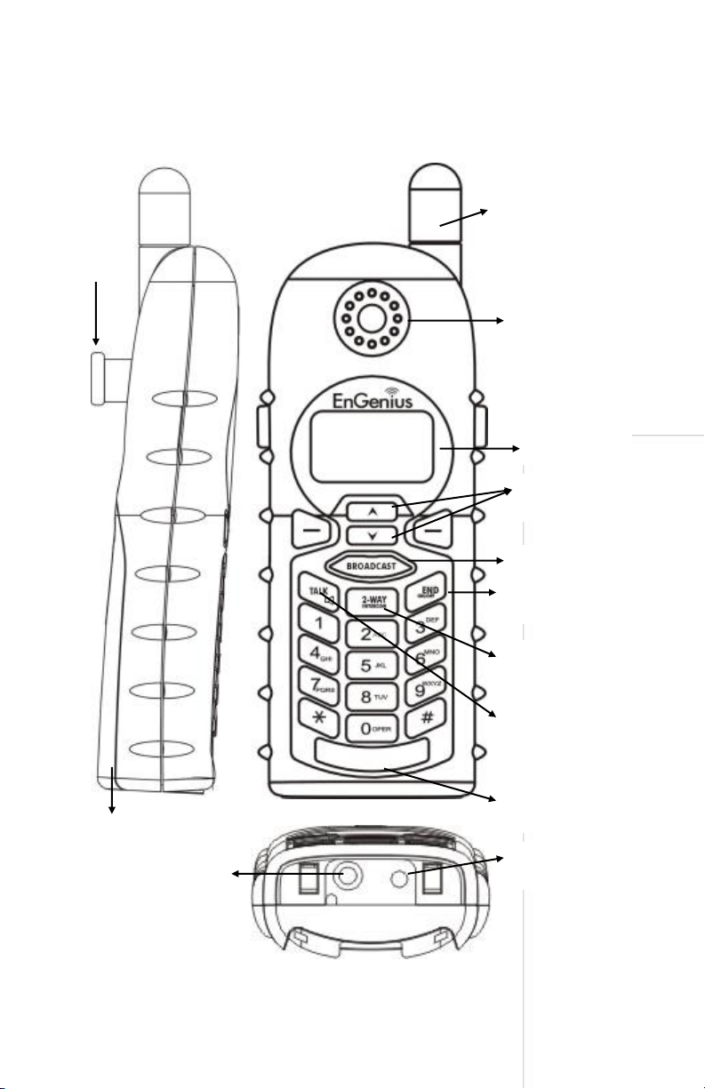
Handset Illustration
Ante nna
Receiver
Bel t Clip
Holder
Vol ume control /
Scrol ling
Broadcast key
Travel charger jack
Hea dset jack
(2.5mm)
Ba tte ry pack
4-li ne LCD
END & Power
ON/OFF key
2-WAY/
INTERCOM
TALK/FLASH/
(For SIP)
Microphone
Page 13

~13~
Handset Features
Basic Handset Features
1.
4-Line LCD (Liquid Crystal Dis play)
a.
The LCD display has LED (Light Emitting Diode) for backlighting.
b.
The 1st line of LCD consists of icons .
c.
Icons explanation from left to right
(1) RSSI level (Receive Signal Strength Indicator)
During a call, the number of bars is proportional to
the radio s ignal strength received.
(5)
DuraFon-SIP
REDIAL MENU
(1)(2) (3) (4) (6)
(2)
Link mode
(2.1) Call in-progress (ON/OFF-Hook)
Indicates if the phone line is in the OFF-Hook s tatus.
12
(2.2) Intercom in-progress
Indicates if Intercom mode is a ctive.
Indicates the Handset ID that is sending the intercom call.
(3)
L
1
Line, Sound and Indication
(3.1) Line Indicator
Indicates when using line 1 or the incoming call from FXO line.
S
1
(3.2) SIP Indicator
Indicates when using SIP or the incoming call from SIP.
(3.3) Enable ringer
(3.4) Disable ringer
(3.5) Ringer and vibrate mode
(3.6) Vibrate mode
(3.7) Message waiting indicator
(4)
PA
Disable PA and indicate speaker phone
(4.1) Indicates if the incoming broadcast is disabled.
(4.2) Speaker indicator
Indicates if the speakerphone is active.
(5)
11
Two-Digit Handset ID
Di splays the 2-digit Handset ID of owner.
(6)
Battery Strength
Number of bars is proportional to the amount of battery time remaining.
d.
The 2nd and 3rd lines of the LCD, maximum 16-characters each, display
status, message, menu selections, or user-editable alphanumerical
characters.
Page 14

~14~
e.
The last line displays the left and right soft keys.
2.
Ringer
a.
Rings to an incoming call and intercom call.
b.
Distinctive alert sounds indicating various events:
(1)
Si ngle beep: successful key entry.
(2)
Double beep: indicates power on/off.
(3)
Triple beep: failed operation.
(4)
Peri odic 1-Long 2-Short beeps (every 1 mi nute): low battery wa rning; out of
range; call on hold.
Re:
No beep: invalid key entry.
3.
TALK/FLASH ( )
a.
Places or answers a telephone or intercom call .
b.
Sends a Flash signal to the phone l i ne to retrieve a dial tone after the call
ends, or to perform the Call Wai ting feature provided by local phone
companies during a call.
4.
SPEAKERPHONE ( )
Press and hold the key for over 2-seconds to enable/disable the speakerphone
duri ng incoming, outgoing or i ntercom call.
5.
2-WAY INTERCOM (( ))
a.
Places an intercom call to another handset, a group handset (group paging)
or all registered handsets.
b.
Intercom calls are digital, full duplex, and are conducted without the
assi stance of the base station.
6.
BROADCAST ( )
a.
Half duplex broadcasting to handsets for immediate announcement.
b.
Half duplex broadcasting to base stations .
Re:Press the key on the left top corner of the handset to activate
the broadcast function.
7.
Left/Right Soft Keys ( )
a.
Make menu selection.
Page 15

~15~
8.
Up ( ) /Down ( ) Scrolling Keys
a.
Scroll through records and menu selections.
b.
Adjust receiver voi ce volume when in the Talk mode.
c.
Press to enter received cal l log when in the Standby mode.
d.
Press to enter phonebook when in the Standby mode.
9.
END; On/Off Key ( )
a.
Ends a call.
b.
Leaves current menu operation, up one level.
c.
Press for 3-s econds to turn off the power.
Additional Handset Features
1.
Multiple Handsets Registration
a.
Up to 10 handsets can be registered to a base station.
b.
ID 10-19: Individual Handset IDs.
c.
ID 1~7: Group IDs. Hands ets can “subscribe” from the handset menu to
group(s ) and be paged when a landline cal ler or an intercom caller enters a
Group ID.
2.
Ringer Vibrator
a.
Two (2) options for Line (incoming call ) ringing and intercom ringing.
b.
Six (6)-level ringer volume selections
(Off/Low/Medium/High/Vibrate/Vibrate & High) for each option.
c.
Eight (8) ringer type selections for each option.
3.
Cal l er ID
Displays incoming call phone number and name on the LCD (needs Caller ID
service from local telephone company).
4.
Cal l Waiting with Caller ID
Displays 2nd incoming call information on the same phone line when 1st call is in
progress (needs Call Waiting with Caller ID servi ce from local telephone
company).
5.
Name Tagging with Cal l er ID
Match the Caller ID with the phone book entries; once matched, the LCD
screen will display the name or nickname i nstead of pure Call er ID info (needs
Cal l er ID service from local telephone company).
Page 16

~16~
6.
DND (Do Not Disturb, i.e., Silent Ring)
7.
Cal l Logs
a.
Redial: Stores 10 phone numbers (up to 26-digits each) dialed most
recently. Can perform last-number redial on all 10 numbers.
b.
Received and New Call Log: Total 50-entries (16-di gi t phone number, 16character names, and Date/Time stamp), needs Caller ID service from l ocal
telephone company.
c.
Phone numbers and names can be saved into phone book whil e in dis play.
8.
Cal l Manager: Includes: blocking incoming call, outgoing cal l and assign line
dedication, li ne selection.
a.
Incoming Call:
a-1. PA On/Off: Enable or disable the Broadcast feature from other
handsets or the base station. When PA is Off, the handset cannot receive
Broadcas t calls from the base station or other registered hands ets, but it
can Broadcast to the base s tation or other registered handsets.
a-2. Line On/Off: Enabl e or disable the ability to receive incoming cal l s
from telephone line call . When Line is Off, the handset cannot receive
incoming calls from a telephone line call, but i t can stil l make outgoing
calls.
a-3. Int. On/Off: Enabl e or disable the Intercom from other hands ets or the
base s tation. When Int. is Off, the handset cannot receive Intercom calls
from the base station or other registered handsets, but it can Intercom to
the base station or other registered handsets.
b.
Outgoing Call
Select the mode of li ne selection (Auto/Manual/Predefine line/Off) when
you make a line call.
b-1. Auto: A handset will select one of avai lable lines from subscribed
bases before maki ng an outgoing cal l . (Default)
b-2. Manual: A handset will be prompted to s elect from a list of available
lines before making an outgoing cal l . (1 for telephone line, 5 for SIP call)
Page 17

~17~
b-3. Off: Disable the capabi lity to make an outgoing call.
c.
Cal l Barring
c-1. Block users from dialing long distance or international calls.
c-2. Up to 5-digits of each Cal l Barring setting, up to 5-entries allowed.
Changing requires you to enter the “Call Settings” (MENU-4-3).
Note: You must key i n the accurate us er ID and password to perform this
feature. The default pass word is “0000.”
9.
Any Key Answer (except and SILENT soft Key)
a.
If you enable Any Key Answer while you have two incoming line call s
simultaneously, you can answer the SIP cal l or PSTN cal l by pressing
the scrolling key.
10.
Key-Guard
a.
When the Key-Guard is selected, all keys will be locked.
Press UNLOCK (Left) soft key followed by * to release it.
b.
The Key-Guard will be automatical ly enabled once returni ng back to idl e
mode for 15-seconds.
11.
Dial ing Prefix
a.
Up to 14-digits, including pause(s), one access code can be preprogrammed to be added automatically in front of the dialed number
when di ali ng from call logs, phone book, and dial-and-send dialing.
12.
Cal l Hold
a.
Places call on hold.
13.
Mute
a.
Press MUTE (Left) soft key during talk, the handset microphone will be
muted.
Press UNMUTE (Left) soft key to release it.
14.
Phone Book
a.
50-entries, each stores a phone number or handset ID (up to 26-digits) and
name (up to 16-characters).
b.
Alphabetically sorted display and search by letter.
c.
Dial from displ ay.
d.
During the stand-by mode, you can enter the phone book by pressi ng
Page 18

~18~
the scrolling key.
e.
Phone Book transfer via air
i. Transfer a specific Phone Book to one handset or all registered
handsets
ii. Transfer all Phone Books to one handset or all registered handsets
15.
Key Tone
a.
Four-l evel Key Tone volume selections (Off/Low/Medium/High).
b.
Four Key Tone type selections .
16.
Cal l Timers
a.
Displays call time duration for current call , during and immediately after
the call .
17.
Programmable Feature Call
a.
Allows user to pre-program the most frequently used Feature codes into
the DuraFon-SIP, which is adjunct to the PBX system.
b.
Up to 10-entries can be saved.
c.
Once the feature code has been programmed, you can quickly perform
those functions during the call by pressing the OPTION soft key.
18.
Menu Di spl ay
a.
To avoid mis-setup in the “Cal l Settings”(MENU-4), “Phone Settings”
(MENU-5), and “Base Settings” (MENU-6), these settings can be hidden.
b.
The Handset pas sword is required before entering Menu Displ ay (MENU-
8), the default handset password is “0000.”
c.
When dis abling the settings, they will no longer be displ ayed unless
enabled by entering Menu Display again.
19.
PA On/Off
a.
Enabl e or disable the Broadcast function.
b.
When PA is Off, the handset cannot receive Broadcast from the base
station or other registered handsets; but it can broadcast to other
regis tered handsets.
20.
Group Setting
a.
Allows the handset to subscribe to one or several groups.
Re: Up to 7 groups (1~7) can be subscribed.
21.
Custom Name
a.
Change the “DuraFon-SIP” screen to the desired wording or i nfo, such as
Page 19

~19~
the handset user’s name.
Re: Up to 32-characters can be entered.
22.
Change Pwd
a.
Change the handset password, which requires entering the Cal l Barring
(MENU-4-3) and Menu Display (MENU-8).
Re: Default PIN is “0000.”
23.
DTMF Duration (from web)
24.
Programmable Flash Key Timing (from web)
25.
Assign Next Handset ID for New Handsets
a.
Use a registered handset from MENU-6-1 to assign a Next Handset ID to a
new handset.
b.
If you do not assign Next Handset ID, the system will automaticall y assign a
handset ID to a new hands et.
c.
When entering the Base Settings, a PIN is required. The Default is “0000.”
26.
Clear Handset
a.
Use a registered handset from MENU-6-2 to remove the other registered
handset, in case the other registered handset is defected.
b.
Once the other registered handset is clear, the user is able to regis ter a
new handset in its place.
c.
When entering the Base Settings, the PIN is required. Default is “0000.”
27.
Change PIN
To change the base PIN, enter the “Base Settings” (MENU-6-3).
a.
Use a registered handset to change the PIN from MENU-6-3.
b.
The default PIN is “0000.”
c.
When entering the Base Settings, the PIN is required. The default PIN is
“0000.”
28.
Auto Hang Up Feature (from web)
a.
From Web, “System-Base Settings -Auto Hang up” to turn On/Off this auto
hang up feature.
b.
If turning On the feature, the handset will automatically hang up the cal l
when the far-end hangs up its call .
29.
Mic Gain
Change the handset microphone gai n based on the handset’s use in different
environments – Qui et, Normal and Noisy environment.
Page 20

~20~
a. This requires entering the “Phone Settings ” (MENU-5-1).
30.
Headset Ring
Change the ri nger emitting either from the handset speaker or the headset
receiver.
a. This requires entering the “Phone Settings ” (MENU-5-8).
31
Base Intercom Auto-Answer (from web)
a.
From Web, “System-Base Settings -Base Intercom Auto-Answer” to turn
On/Off the Intercom Auto-Answer feature.
b.
Default is ON, If turning OFF the feature, you will need to press the base
Intercom or Broadcast key to answer handset Intercom calls to the base.
Page 21
~21~
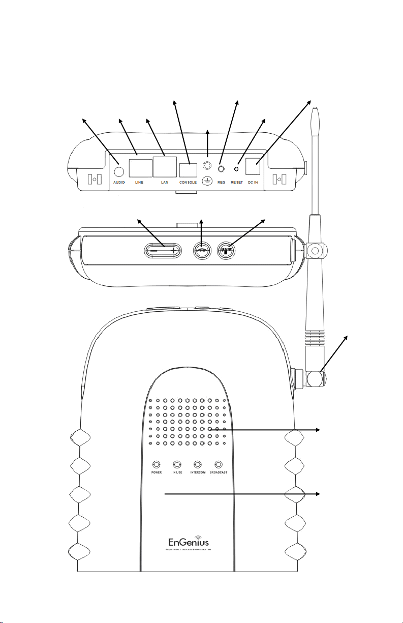
Base Illustration
GROUND
DC In
AUDIO IN
CONSOLE
LINE
REGISTER
RESET
LAN
Broadcast
Inte rcom
Vol ume
Ante nna
Receiver
Microphone
Page 22

~22~
Base Features
Basic Base Station Features
1.
Audio-In Jack (3.5mm)
Connect to an external device for music on hold .
2.
FXO Jack (L1)
Standard RJ-11 connector to plug in the telephone line.
3.
Ethernet Jack
Standard RJ-45 connector to plug in the Ethernet (LAN) l ine.
4.
Console Jack
Jack for console (Type-B USB connector).
5.
GND
Connecting the ground cable.
6.
REG button for Registration and Page
a.
Press and hold this REG button until the “INTERCOM” LED flashes status to
enter registration mode.
b.
To s earch for a misplaced handset; press “REG” button, all registered
handsets will beep for 30-seconds. Press “REG” again or any key on the
handset to stop.
7.
RESET Button
a.
Restores base station to factory settings .
b.
Reset button is intended to prevent accidental system reset.
c.
All hands ets (including administrator) and additional base(s) need to be reregis tered after a bas e station reset. The web confi guration is also to reset
to factory settings.
8.
DC In: to plug in the 12V DC power adapter.
Page 23
~23~
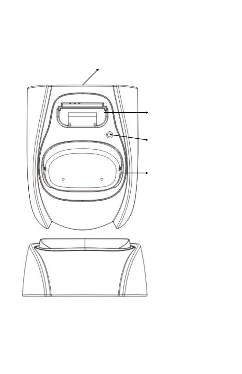
Charger Illustration
DC In
Spare Battery Cha rging
Sl ot
Spare Battery Cha rging
Indicator
Ha ndset Charging Slot
Page 24

~24~
Charger Features
1.
DC In
Connects to Charger AC Adapter.
2.
Handset Charging Slot
a.
Charges handset battery when handset is placed in the cradle.
b.
Refer to the handset LCD for charging status .
(1)
Chargi ng: battery status bar is running and the LCD screen shows: “Cha rging.”
(2)
Fully Charged: battery status bar stands still and the LCD screen displays
“Charge Complete.”
(3)
Charge Fail: If an error occurs during charging mode, the LCD screen will
di splay “Charge Fail.”
3.
It is impossible to overcharge the battery using this charger.
4.
The charging station adapter can al s o be used as a travel charger. However,
you cannot turn off the power while you charge the handset via the travel
charger. A warning message, “Unplug Travel Charger then OFF” will be shown
on the LCD.
Notes:
1. Fully charge battery packs before first use.
2. Ha ndset will “power on” automatically when placed on the charging
sl ot.
3. Howe ver, if you drain the battery completely, it will ta ke
approximately one minute for the handset to auto power on.
Page 25

~25~
Getting Started
Base Station Installation
1.
Plug the transformer end of the base
station AC/DC adapter into a standard AC
electrical power outlet, pl ug the other end
into the “DC In” jack on the back of the
base s tation.
2.
Plug the phone cord into the “RJ11” FXO jack.
3.
Plug the Ethernet cord into the “RJ45” LAN jack.
PS:
For SIP configuration, please see page 51.
Page 26

~26~
Handset and Charger Installation
1.
Plug the transformer end of the Charger AC/DC adapter into a standard AC
electric power outlet, plug the other end into the “DC In” jack on the back of
the Charger.
2.
Ins tall the battery pack onto the handset.
3.
Ins tall the handset antenna.
4.
Place the handset onto the charger slot.
5.
Fully charge the battery for three hours before use.
6.
The phone system is now ready to perform basic functions such as maki ng and
receiving phone cal ls and intercom cal ls. No base station or handset
programming is needed for basic operations.
Note:
1. Handset(s) packaged along with a Base Station are pre-registered at
the fa ctory. If you have a new handset, you will need to register the
ha ndset with the base station in order to be recognized as a member
ha ndset by the base(s) and by other handsets. See Handset
Regi stration.
2. Ful ly cha rge battery packs before the first usage.
Page 27

~27~
Basic Operations
Operation Modes
Both the base station and handset have feature levels that can only be accessed
when in certai n modes.
A. Base Operation Modes
1.
STANDBY mode- this is the default mode. The page key is active in standby
mode onl y. The bas e “Power” LED will light up during this mode.
2.
TALK mode- the base station operates in this mode during a phone call. The
“In Use” LED will light up only for a FXO call.
3.
REGISTRATION mode- the base station enters this mode by pressing and
holding the REG button for 3-seconds. The INTERCOM LED will be bl i nking in
“Registration” mode, and a prompt sound will be emitted.
B. Handset Operation Modes
1.
STANDBY mode- this is the default mode.
11
DuraFon-SIP
REDIAL MENU
a.
If there is no on-going activity, the handset
automatically goes into SLEEP/STANDBY mode to save
battery power.
b.
The handset can be turned off completely by holding
down the key for 3-seconds.
c.
The standby screen display (custom name) can be
edited.
d.
The 2-dight number represents the handset ID.
2.
MENU mode
a.
Press the (Right) soft function key to activate Menu
mode.
Main Menu
1.KeyGuard
SELECT BACK
b.
In Menu mode, the handset settings and information
contained in the memory can be changed.
c.
The functions available through the Menu selection
are covered in greater detail starting on page 63.
d.
The Menu structure display as below:
Page 28

~28~
3.
Menu Tree
Menu 1.KeyGuard
2.PhoneBook
3.Sounds
2.Ring Tone
1.Ring Volume
3.Key Voulme
4.Key Tone
4.Call Settings 1.Dial Prefix
2.Group Setting
6.Language
3.Contrast
4.Backlight
5.Name Tag
5.Phone Settings 1. Mic. Gain
2.Any Key Talk
6.Base Settings
Enter
Base PIN:----
7.Registration 1.Register
2.Deregister
8.Menu Display
1.Call Setting
Enter Password
----
2.Phone Setting
3.Base Setting
8.Change Pwd
9.Headset Ring
3.Call Manager
1.Assign Next HS
3.Change PIN
2.Clear HS
3.Remote REG
Outgoing
Incoming
4.Feature Call
1.PA On/Off
2.Line On/Off
3.Int. On/Off
1.Auto
2.Manual
Call Barring
3.Off
7.Custom Name
Page 29

~29~
Making a Telephone Call
1.
Press , wait for dial tone, then enter the phone
number.
11
Press REDIAL
or dial number
REDIAL MENU
L
1
2.
Alternatively, you can enter the phone number first, then
press
key.
When using this method, you can use the CLEAR (Left) and
DELETE (Right) soft keys to edit the number entered.
“Delete” erases the last digit entered. “Clear” erases the
entire line but remains in the dial-and-send dialing.
432398765
CLEAR DELETE
3.
Speed dial by accessing the entries in the phone book.
(Menu2)
Main Menu
2.PhoneBook
SELECT BACK
Joe
033289289
ADD
OPTION
a.
Press or scroll ing key to enter the phone
book.
b.
Press to dial the number.
4.
To abort dialing, press key.
Notes:
1. I f a link ca nnot be established, the LCD will show “Base not found”
afte r a 6-second time out.
2. A call duration timer will start displaying the length of the call after
a li nk is established.
Page 30

~30~
Making a 2-Way/ Intercom Call
The DuraFon-SIP Cordless Phone System offers private, Intercom/ 2-Way Radi o calls
independent of the base station. Intercom/ 2-Way communication can be placed
between handsets.
1.
Press key followed by a two-digit hands et ID or
Group ID.
Enter Ext #:
##
PHBOOKBASE
2.
Press key to end the call.
Notes:
1. I ntercom calls can be made regardless of the Base Station being
pres ent.
2. I f a Group ID is entered, the first handset (belonging to that
group) that answers will establish a link with the caller. Se e
Ha ndset Group Subscription.
3. I f a link cannot be established, the LCD s hows “Paging timeout”
afte r a 35-second time out.
Making a Broadcast
Handset-to-Handset Calls
1.
Broadcas ting to al l handsets
11
PA to ALL
REDIAL MENU
a.
Press and hold key from one handset.
b.
Start speaking the broadcast mess age once you hear the key tone; the
speakerphone of destination hands ets will open when it receives the voice.
Re: the i nitiating handset needs to press and hold key while
speaking or broadcasting.
c.
Release key to end broadcasting.
2.
Broadcas ting to a group of handsets
11
PA to Group #91
REDIAL MENU
91
Page 31

~31~
a.
Enter the Group ID and then press and hold
key.
b.
Start speaking the broadcast mess age once you hear the key tone; the
speakerphone of destination hands ets will open when it receives the voice.
Re: the i nitiating handset needs to press and hold key while
speaking or broadcasting.
c.
Release key to end the broadcasting.
3.
Broadcas ting to an individual handset
11
PA to HS #12
REDIAL MENU
12
a.
Enter the Handset ID and then press and hold
key.
b.
Start speaking the broadcast mess age once you hear the key tone; the
speakerphone of destination hands ets will open when it receives the voice.
Re: the i nitiating handset needs to press and hold key while
speaking or broadcasting.
c.
Release key to end the broadcasting.
Redial
1.
Press REDIAL (Left) soft key.
11
DuraFon-SIP
REDIAL MENU
2.
The LCD shows the last phone number dial ed. To dial this
number, press key.
3.
Use or key to scroll through the last 10 phone
numbers dialed. Select and press key to dial the
selected number.
Dialed #1:
033289289
OPTION BACK
Note: Intercom numbers (Handset ID) are not stored in the
las t 10 numbers dial ed l og.
Page 32

~32~
Receiving a Telephone Call
1.
When an incoming call arrives, the LCD wil l show the Caller
ID mess age, and the ringer will ring or vibrate unless the
ringer has been turned off.
Joe
033289289
SILENT
11
1
L1
2.
If the handset is on the charger cradle (ringer will be
temporarily switched to “Ring” i f it has been s et to
“Vibrate”), lift the handset and press key to start a
conversation.
Re:
You can turn on the “Any Key Talk” from MENU-5-2.
Notes:
1. You can press SILENT (Left) soft key i f you choose to ignore the call.
Unlike turning off the ringer (from the handset menu), the SILENT
key ope ration is valid only for the current call.
2. I f Cal ler ID service is available, the LCD wi ll display the incoming call
information. If the LCD shows “Private” or “Unknown,” the caller or
the ori ginating phone company ma y have blocked the caller’s
information.
Receiving an Intercom Call
1.
When an intercom call arrives (called from other handsets,
ex. Handset 12), the ri nger will ring or vibrate unless the
ringer has been turned off. Press to answer the
intercom call.
Incoming page
from Ext #12
SILENT
11
L
1
2.
If the handset is on the charger cradle (ringer will be
temporarily switched to “Ring” i f it has been s et to
“Vibrate”), lift the handset and press key to start a
conversation.
Page 33

~33~
3.
If the handset is not on the cradle and MENU-5-2 “Any Key Talk” setting is “On,”
press any key (except and the SILENT soft key) to answer.
Notes:
1. The LCD displays the caller’s Handset ID.
2. You can press the SILENT (Left) soft key i f you choose to ignore the call.
Unlike turning off the ringer the SILENT key operation is valid only for
the current call.
Ending a Call
To end a telephone or intercom cal l , press key, or place handset into charger
cradle.
Adjusting Handset Receiver (Earpiece) Voice Volume
1.
Voice volume can only be adjusted duri ng a call.
00:00:15
Volume: 3
11
MUTE OPTION
L
1
2.
There are 6 levels of vol ume selections. Use or
key to adjust.
3.
The new setting wil l remain effective for all future calls
until changed.
Adjusting Handset Speakerphone Voice Volume
1.
Voice volume can only be adjusted duri ng a call (in
speakerphone mode).
00:00:15
Volume: 3
11
MUTE OPTION
L
1
2.
There are 6 levels of vol ume selections. Use or
key to adjust.
3.
The new setting wil l remai n effective for all future calls
until changed.
Page 34

~34~
Placing a Call On Hold
1.
When a call is in progress, it can be put on hold by press i ng
OPTION (Right
) soft
key and the * key.
You have a
call on hold
UNHOLD OPTION
2.
To return to the conversation, press UNHOLD (Left) soft
key.
Notes:
1. Handset LCD displays when a call is on hold. An alert tone (a beep)
every 30-seconds will remind the handset that a call is on hold.
2. I f the operation (e.g., call transfer) fails after putting a call on-hold,
the he ld call may be dropped.
Mute
1.
After a link is establ is hed, you can press MUTE (Left) soft
key to mute the handset microphone.
00:00:15
MUTE
11
UNMUTE OPTION
L
1
2.
When mute is active, the other end will not hear your
voice, but can still speak to you.
3.
To l eave the mute state, press UNMUTE (Left) soft key. Mute is effective only
for the current call.
Do Not Disturb (Silent Ring)
1.
Enter the key sequence MENU-3-1, then select “Off.” Press
SELECT (Left) soft key to confirm your choice. This will turn
off the ringer until it is turned on again from the menu.
Joe
033289289
SILENT
11
L
1
2.
For temporary sil encing the ringer when an incoming call
arri ves, press SILENT (Left) soft key.
Page 35

~35~
Key Guard
1.
To prevent accidental dialing, you can press MENU (Right)
soft key, then press “1” to select Key Guard option. The
handset keypad is now locked. No key entry i s accepted.
Locked
No new calls
UNLOCK
2.
To unlock the keypad, press UNLOCK (Left) soft key, then,
within 2-seconds , press the digit * to unlock.
Press * to
confirm unlock
3.
Once returning back to standby mode for 15-seconds, the
Key Guard will be automatically enabled.
4.
Key Guard is in effect until unlocked.
Battery Recharge and Replacement
1.
Charge the battery when one or several of the following happen:
a.
Phone beeps twice (every 60-seconds in talk mode, every 10-minutes in
standby mode).
b.
Battery icon is empty.
c.
Phone does not respond when a power On/Off key i s press ed.
d.
LCD and backlighting become dim.
e.
Talk range shortfal l is experienced.
2.
You can replace the handset battery after placing the call -in-progress on hold
and press key. To retrieve the call on hold, press Talk key again after
replacing the battery and powering on the handset.
3.
Battery talk time and standby times vary depending on the talk/standby
pattern and the operating distance. Putting the handset back on the charger
cradle as often as possible is recommended for best performance.
Use only the manufacturer’s provided battery and charger!
Page 36

~36~
Advanced Operations
Handset Registration
1.
If your handset(s) is purchased as part of a system, it has been pre-registered
with the base s tation at the factory.
2.
If the Handset ID is “00,” this means it is a new handset or the ID has been
erased. You will need to register the handset with the base station.
3.
Registration:
a.
Press MENU-7 to enter the registration mode.
Main Menu
7.Registration
SELECT BACK
b.
Press and hold the base’s REG button for 3-seconds
until the INTERCOM LED li ghts up and flashes. The base
station will emit a prompt sound to remind you the
base station is in the registration mode.
c.
Press handset key 1 , this completes the registration
process. The base station will assign a handset ID
between 10 and 19 automatically. The assigned ID will
be displayed on the handset LCD, indicating successful
regis tration.
Registration
1.Register
SELECT BACK
d.
Repeat above steps for all additional handsets.
4.
De-registration:
a.
You can de-register the handset you’re usi ng from the
base station. De-registration will reset the Handset ID
to 00, erase the system security code, and free up the
handset ID for future registration.
Main Menu
7.Registration
SELECT BACK
b.
After de-registration, the handset will not be able to
use the base station to make or receive phone cal ls, nor
can it intercom other handsets.
c.
Press MENU-7 to enter the registration mode.
Registration
2.Deregister
SELECT BACK
d.
Press and hold the base’s PAGE button for 3-seconds
until the In Use INTERCOM LED lights up and flashes,
al s o the base station wil l emit a prompt sound to
remind you the bas e s tation is in the de-registration
mode.
e.
Press the handset number key 2 , this completes the
Page 37

~37~
de-registration process. Upon s uccessful deregis tration, the handset display will show “Please
regis ter.”
Notes:
1. The ba se station has a 30-second registration timeout starting when
you pres s the REG button. The handset has a 6-second registration
time out starting when the registration or de-registration option has
be e n selected. The base station and handset will automatically exit
registration mode after timeout.
2. Repeat registration or de-registration process if unsuccessful.
Handset Group Subscription
1.
Up to nine handset groups (1-7) can be defined, and
handset users can decide which group(s) they want to be in.
Main Menu
4.Call Settings
SELECT
BACK
2.
For example, Group 1 represents the Customer Service
Group, Group 2 represents the Sales Group
and Group 3 is the Marketing Group. Suppose that handset
11 wants to receive incoming ri ngs for all Sales and
Marketing related calls. Then handset 11 will need to
“subscri be” to Group 2 and Group 3.
Call Settings
2.Group Setting
SELECT
BACK
3.
Group Selections:
Subscribed
None
OPTION BACK
a.
b.
Press handset MENU -4 to enter the Call Settings menu.
Press number 2 , handset enters group s etting menu.
c.
Press OPTION soft key fol lowed by 1 key to subscri be
the group (“#”, #:1~7). Enter 1~7.
Enter group to
subscribe
#
BACK
d.
Repeat for all desired groups .
e.
Delete group selections by pressing OPTION soft key
followed by 2 to Unsubscri be the group.
Enter group to
unsubscribe
#
BACK
Page 38

~38~
Notes:
1. The ha ndset can change group affiliations at any ti me.
2. The ba se station is not responsible for group assignments.
Consequently, it cannot de-subscribe a handset from a group.
3. Whe n an intercom caller enters a group ID, all handsets subscribed to
thi s group will ring. The first handset to answer will establish a link
wi th the caller. Afterward, it is a one-to-one call, not a one-to-many
call.
Call Transfer
While a telephone call is in progress, you can transfer it between different
handsets.
Direct transfer
1.
Press OPTION (Right) soft key, followed by the * key to put
the cal l on hold.
00:00:15
Volume: 3
11
MUTE OPTION
L
1
You have a
call on hold
UNHOLD XFER
Enter Ext #:
##
11
CANCEL
L
1
2.
Press OPTION (Right) soft key, followed by selecting XFER
item and then entering the destination handset ID, then the
held call will be trans ferred directly.
After the call is transferred to the destination hands et, the
original handset will go back to standby mode automatically.
Indirect transfer
If you want to talk to the destination handset before the call is
transferred, you can follow the below method:
00:00:15
Volume: 3
11
MUTE OPTION
L
1
1.
During the call, press key, then enter the destination
handset ID.
Page 39

~39~
2.
Press the of the destination handset to answer the
intercom call, you can now talk to the destination handset.
After talking, press to end the intercom cal l , and then
the destination handset is able to pick up the incoming call
automatically.
Enter Ext #:
##
11
CANCEL
L
1
After the call is transferred to the destination hands et, the
original handset will go back to standby mode automatically.
Notes: If the destination handset does not answer after paging it or
trans ferring timeout, the call i s routed back to the originating handset.
Phonebook Operations
1.
You can store up to 50-entries in the phone book. Each
entry can contai n a phone number or handset ID (up to 26digits) and a name (up to 16-characters).
Main Menu
2.PhoneBook
SELECT BACK
2.
To access the phone book, press MENU (Right) soft key,
followed by 2 or press scrolling key while the
handset is in standby mode.
Joe
033289289
ADD
OPTION
Name?
_
Caps = *
SAVE
DELETE
3.
To add a new entry:
a.
Press ADD (Left) soft key.
b.
Enter the name when LCD prompts “Name?” Use
DELETE (Right) soft key to delete the las t digit entered.
When completed, press SAVE (Left) soft key to save.
Re: Up to 16-characters can be entered as the name.
c.
You wil l then be prompted to enter a number for the
name just entered.
Re: Up to 26-digits can be entered as the number.
Number?
_
SAVE
DELETE
Page 40

~40~
d.
After entering the number, press the SAVE (Left) soft
key to save this entry into phone book.
e.
Enter a phone book entry without a name; all records
without a name will be pl aced on the top of the phone
book li s t.
f.
To enter the name, press the corresponding keypad
number one or more times according to the order of
the character on the key.
See table below for a list of available characters and
their orders. For example, press 2 once for the
character “A,” twice for “B,” etc.
Notes:
1. When entering a phone number, the cursor automatically advances to the
ne xt di git field. Us e
or s crolling key to move the cursor
ba ckward or forward to insert or delete (the digit above the cursor or left
of the cursor if the cursor is on the right of the last digit).
2. When entering a name, the cursor automatically a dvances to the next
cha racter field if you press a different key for the next character. If you
ne e d to enter consecutive characters from the same key, you can wait for
the curs or to advance or use
or scrolling key to move the
curs or backward or forward manually. Also use or to move
the curs or to insert (to the left of the cursor) or delete (the character
above the cursor or left of the cursor if cursor is on the right of the last
cha racter).
3. By default, all letters are entered in upper case. Use the * key to toggle
be tween upper and lower cases.
4. A “Pause” entry represents a 1-second delay in dialing the following digits,
which is useful when calling a sequence of segmented numbers (e.g.,
access codes, credit card numbers, auto-attendant entries, etc.) Pause is
ente red by pressing the # key twi ce (LCD displays P). Entering pause
twi ce (PP) will result in 2-seconds pause in the dialing.
Page 41

~41~
5. Chara cter Table:
Key
Chara cters and Orders
1
‘ + , . * ( ) & 1
2
A B C 2
3
D E F 3
4
G H I 4
5
J K L 5
6
M N O 6
7
P Q R S 7
8
T U V 8
9
W X Y Z 9
0
0
*
Caps – when in character editing.
*– when in number editing.
#
Space & # – when in character editing.
# & P (Pause) – when in number editing.
4.
The entries are alphabetically sorted and stored as a list in an ascending order
(A to Z) from the top of the list.
5.
The first line of the LCD display shows the name and the 2nd line shows the
phone number. If the phone number is longer than 16-digits, press OPTION
(Right) soft key and select Option 3 “View Number” to view the complete
number.
6.
To s earch for a record:
a.
Use scrolling key to enter the Phone Book mode.
b.
Press a key that corresponds to the fi rst character of the name you are
looking for.
c.
For example, you are looking for “EnGenius,” then press the number 3
twice.
d.
Use or scrolling key to locate the exact record you are
looking for.
7.
To erase phone book:
Joe
033289289
ADD
OPTION
a.
Use or scrolling key or the alphabetical
search method to locate the record to be erased or
edited.
Page 42

~42~
b.
Press OPTION (Right) soft key to enter the option menu.
c.
Press 1 to erase the desi nated phone entry.
Delete entry?
Tom
12345678
YES
NO
d.
LCD shown “Delete entry?” Press YES (Left) soft key to
confi rm your change.
8.
To edit phone book:
a.
Use or scrolling key or the alphabetical
search method to locate the record to be erased or
edited.
Joe
033289289
ADD
OPTION
b.
Press OPTION (Right) soft key to enter the option menu.
Name?
_
Caps = *
SAVE
DELETE
c.
Press 2 to edit the designated phone entry.
9.
Dial from displ ay:
a.
Press or
to dial the phone number or Handset ID displayed.
10.
To transfer the phone book:
To transfer the phone book, both parties have to enter the phone book transfer
mode first by following below:
a.
Press OPTION (Right) soft key followed by 5 or by s crolling
key to transfer when the handset is in phone book mode.
b.
For the phone sending party, press 1 to enter the s ending mode.
i. Either press TX ALL (Left) soft key to transfer all phone book entries to
another handset(s).
ii. Or press TX ONE (Right) soft key to transfer one entry to another
handset(s).
iii. Press the 2-digit handset ID or group ID, then select al l phone book
entries or one entry to be transferred.
Re: “00” means all hands ets.
iv. During phone book transfer, the LCD shows “Sending” and 2-digit
countdown on the LCD to indicate the phone book numbers which are
pending.
c.
For the phone book receiving party, press 2 to enter the receive mode.
i. When entering the receivi ng mode, the LCD s hows “Ready.”
Page 43

~43~
ii. Start to receive the phone book, the LCD shows, “Get phone book from
Ext. # : xx.”
iii. A beep is emitted when receiving each phone book.
iv. When the phone book i s being received, a 2-digit countdown shows on
the LCD to indicate the phone book numbers that are pending.
Re:
Since the phone book transfers through the wireless interface, i t may
partially miss transmission if there is any interference.
11.
To transfer phone book vi a web:
You can edit/store 50-phone book entries via the web interface. The base can be
used as the sending party.
a.
Place the receiving handsets to Receiving mode, by pressi ng OPTION (Right)
soft key fol l ow by 5 , 2 to enter Receiving mode. The LCD shows “Ready.”
b.
Press “Transfer” button on the web i nterface of the base to send up to 50-
entries of the phone book.
Re:
The handset will not update any phone book when it stores up to a
maxi mum of 50-entries.
Programmable Feature Call
1.
If DuraFon-SIP base station is ins talled behind a PBX system, it is feasible to preprogram some call features al ong with the PBX’s feature code into the system.
2.
Up to 10 most frequently used feature call codes can be pre-programmed.
3.
Name and enter feature cal l codes:
Call Settings
4.Feature Call
SELECT BACK
a.
Press MENU (Right) soft key while the hands et is in the
standby mode.
b.
Press 4 , followed by 4 to enter the “Feature Call”
menu.
c.
Press ADD (Left) soft key to add a new feature call
entry.
Empty
ADD
d.
Key in the name of the feature call, like editing a phone
book entry, i.e. “PBX Transfer.”
Press SAVE (Left) soft key to confirm.
Page 44

~44~
e.
Key in the feature call code of the correspondeni ng PBX
feature, i.e. F*70.
Press SAVE (Left) soft key to confirm.
Re: “F” represent the Fl ash signal.
Feature Name?
_
Caps = *
SAVE DELETE
f.
The 1st feature call and corresponding feature call code
you entered will appear on the LCD screen.
Number?
SAVE DELETE
g.
Press OPTION (Right) soft key to delete or edit the
feature call you programmed into the system.
PBX Transfer
F*70
ADD OPTION
h.
Repeat the same operations to program the 2nd and
subsequent feature call that you will use frequently.
4.
Using pre-programmed feature call during the call.
a.
Press OPTION (Right) soft key while the handset is in
the Talk mode.
00:00:15
Volume: 3
11
MUTE OPTION
L
1
b.
Press the correspondence number of the feature call
you want to perform, i.e. press “0” to perform the “PBX
Transfer.”
Option:
*.Hold
0.PBX Transfer
#.Phonebook
Page 45

~45~
Notes:
1. Thi s feature call would be useful if the DuraFon-SIP base station is adjunct
to a PBX system or
2. If you ha ve not pre-programmed any feature call into the system, only
“#.Phone book” in the OPTION menu.
3. The DuraFon-SIP’s programmable feature call may not function with all
PBX or Key phone systems due to the diversity of various proprietary
systems.
Caller ID
1.
Contact your local phone company to subscribe to this feature. The phone
system receives and displays Caller ID information transmitted by your local
phone company. This information may include the calling phone number, name,
date and time. This unit can store up to 50 calls of Caller ID information.
2.
The displ ay will show the date and time of the call on the first line, followed by
the name on the second line, and the phone number on the third li ne. An unread
record will have a “NEW” at the end of the first line of the display.
3.
When viewing a call record, the number can be dialed, stored to the phone book or
deleted.
View Call Log
1.
To view the call log, press to enter the Call Log.
Press or
key to scrol l through the numbers and
names when available.
01/04 08:20P NEW
Johnson
423-1234
FORMAT
OPTION
2.
Press OPTION (Right) soft key, you can or
key
to choos e save, delete or clear all.
Option:
Save
SELECT
BACK
a.
Save cal l log:
(1)
Press SELECT (Right) soft key, you can use or
key to scroll the name, and press DELETE to
edit the name.
Then press SAVE (Left) soft key to save the name.
Name?
Johnson_
Cap = *
SAVE
DELETE
Page 46

~46~
(2)
Use or key to scrol l the number, and
press DELETE to edit the number.
Then press SAVE (Left) soft key to save the number.
Number?
4231234_
SAVE
DELETE
(3)
After the above process, the call log is saved into the
phone book.
b.
Delete call log:
Option:
Delete
SELECT
BACK
(1)
Press SELECT (Right) soft key followed by YES (Left)
soft key to confirm deleting.
c.
Clear All:
Option:
Clear all
SELECT
BACK
(1)
Press SELECT (Right) soft key followed by YES (Left)
soft key to confirm cleari ng all Caller ID records.
Call a Caller ID
1.
Press key on idle screen to enter the cal l log, use or
key to scroll the call log.
2.
When screen displays a Caller ID, Press
to dial this number.
Call Manager
“Call Manager” feature al lows four options:
1. The fi rst option is “Incoming.” The handset can be selected to enable receivi ng of
the incoming PA, intercom cal l , line call .
2. The second option is “Outgoing.” The handset can be set to access available
bases automatical ly, manually or as a pre-defined telephone line.
3. The third option is “Call Barring.” The handset can be selected to block the calls,
which are not allowed.
Note: When entering this menu (Call Manager), you must enter the handset’s
password first (4-digits). The default handset pass word is “0000.”
Page 47

~47~
Incoming
1. Press MENU (Right) soft key followed by 4 to enter
the Call Settings mode.
Press 3 to select Call Manager, then enter handset’s
password (4-digits).
Call Settings:
3.Call Manager
SELECT BACK
a.
Press 1 to enable receivi ng PA On/Off.
Re: Default setting is “ON.”
Call Manager
2.Incoming
SELECT BACK
b.
Press 2 to enable receivi ng Line On/Off which includes
FXO l i ne only.
Re: Default setting is “ON.”
c. Press 3 to enable receivi ng Intercom On/Off.
Re: Default setting is “ON.”
(1) By default, all incoming calls will ring all handsets.
When entering this menu, you must enter handset password first (4-di gits).
Re: The default handset password is “0000.”
Outgoing
1. Press MENU (Right) soft key followed by 4 to enter the
Cal l Settings mode.
Press 3 to select Call Manager foll owed by enteri ng
handset’s password (4-digits).
The handset is able to make outgoing calls via the SIP
line or PSTN l i ne.
Call Settings:
3.Call Manager
SELECT BACK
Re: Default setting is “Auto.”
Call Manager
3.Outgoing
SELECT BACK
a.
Press 1 to “Auto.” The hans et is able to make outgoing
calls via an available line and SIP li ne automatically.
Page 48

~48~
b.
Press 2 to “Manual .” When pressing
key in
standby mode, the handset LCD will show the available
line. Press or to scroll the options: 1. SIP,
2. Line. Press 1, you can select the SIP line 1 to make a
call.
c Press 3 to “Off.” The hanset i s disabled from making
any outgoing calls.
Call Barring
1. Press MENU (Right) soft key followed by 4 to enter the
Cal l Settings mode.
Press 3 to select Call Manager, and enter handset’s
password (4-digits).
Press or to scroll the options : select “Call
Barring” to bl ock users from dialing long distance or
international calls. This also blocks incoming call s from
outsi de l ines or other registered handset.
Call Settings:
3.Call Manager
SELECT BACK
Re: Default Call Barring is “OFF.”
Call Manager
4.Call Barring
SELECT BACK
2.
To add the Cal l Barring code:
a.
Once you turn on the Call Barring feature, you can key in
the “Cal l Barri ng” code.
To add one block code, press ADD (Left) soft key then
start entering the Call Barring code. After entering the
Cal l Barring code, press SAVE (Left) soft key to save.
(1)
Up to 5-digits can be edited for the Call Barring
code. For example, if you want to bl ock all cal ls
dialing to Manhanttan, NY area, you can enter 1212
as the Call Barring code.
(2)
If your bas e station is adjuct to a PBX system, please
al s o include that speci fic number to retrieve the
PSTN tone.
Page 49

~49~
b.
Press OPTION (Right) soft key to delete or edit the Cal l
Barring codes.
Call Barring
1212
ADD OPTION
Up to 5 sets of Call Barring codes can be programmed.
c.
If you want to block all outgoing calls, enter “* * *
**” 5 “*” keys, then press SAVE (Left) soft key to
save it, and all outgoing calls will be restricted.
Visual Message Waiting Indicator (VMWI)
VMWI feature supports the FSK message and stutter tone detection, which is
received from the telephone line; it will activate a message icon on the handset.
Notes:
1. A s ubscription to the telephone company’s voice mail service is required.
2. If the handset still indicates the icon, even a fter you have listened to all messages, turn it
off by pres sing and holding “Caller ID” key on the handset.
Adjust Handset Microphone Gain
If you will use the handset in different workplaces or environments, you can adjust
the handset microphone gain to obtain a better voice quality that is suitable for
various locations.
a.
Press MENU (Right) soft key while the hands et is in the standby mode.
b.
Press 5 (Phone Settings ), followed by 1 to enter the “Mic. Gain” menu.
c.
Use or key to scroll the “Standard,” “Medium” and “Low”
options.
d.
If you are using the handset in quiet environments, like an office or
meeting room, the “Standard” level is recommended.
If you are using the handset in a noisy environment, like a factory or
outdoor place, the level of “Medium” or “Low” is recommended.
Page 50

~50~
Adjust Headset Ring
When using the headset, you can change the ri nger to emit from either the handset
speaker or receiver of headset to avoid missing call s.
a.
Press MENU (Right) soft key while the hands et is in the standby mode.
b.
Press 5 (Phone Settings ), fol lowed by “9” to enter the “Headset Ring”
menu.
c.
Select On , so the ri nger emits from the headset receiver; i f Off is
selected, the ri nger will emit from the handset speaker.
Page 51

~51~
SIP Configuration
Introduction
The DuraFon-SIP is a long-range cordless telephone system with bui lt-in LAN and a
traditional FXO port. It provides users the ability to make VoIP or PSTN call s via
different ports. Below describes how to setup the SIP configuration of the DuraFonSIP base from the web.
Application
Typically, the DuraFon-SIP is able to connect to a legacy PBX (or PSTN line) via a
telephone jack, and in addi tion, with an IP-PBX via a networking jack. These two
interfaces are perfectly suitabl e for adjunct telephone s ystems in enterprise
environments as shown i n the following figure.
VoIP Features
- Support 3 VoIP and 1 PSTN line call s simultaneously.
- Each handset has only one SIP account.
- Register Up to 10 SIP accounts and 10 handsets accordingly.
- Flexible Call Manager features to dedicate either the SIP or PSTN call.
- Use G.711U-law for VoIP codec.
- SIP and LAN setting from web configuration.
- Internet interface: 10/100bas e-T LAN port x1
Registration Handsets
- Before setting the SIP configuration, the available handset(s) of the DuraFon-SIP
must register to the base.
- Register handset:
Page 52

~52~
(1) Press and hold the register key on the bas e until the “INTERCOM” LED changes
to a flashi ng status. The base can perform the handset registration while the LED
is flashing.
(2) On handset, enter “MENU, 7, 1” to enter the registration.
(3) The assi gned ID (from 10 to 19) wil l be displayed on handset LCD, indi cating
successful regis tration.
(4) Repeat the above steps for all additional handsets.
Default Settings
Connect the Internet port to the DuraFon-SIP’s LAN port.
IP Address
192.168.1.156
Username / Password
admin / admin
Web Configuration
Open a web browser (Internet Explorer/Firefox/Safari /Chrome) and enter the IP
Address http://192.168.1.156
The default username and password are admin. Once you have entered the correct
username and password, click the Login button to open the web-base confi guration
page. If successful, you will be logging in and see the confi guration of DuraFon-SIP.
Page 53

~53~
LAN Configuration
Note: When you change the LAN IP to DHCP, once you click Apply, the change will
take effect. You will now know the new IP of the DuraFon-SIP in advance of
accessing the web configuration next time.
Base Settings
Note: When you change any of the Base Settings, cl i ck Apply for the change to take
effect. The items shown in gray are not changeable and are reserved for other
versions.
Page 54

~54~
Phone Book
You can store up to 50-entries in the phone book on the DuraFon-SIP base.
- Click the Add phone book button to add entries. Click the Export phone book
button to export this phone book to a specific file in .csv format.
- If you have this contact list file in advance, you can click the Browse button to
select it, and click the Import phone book button to i mport the contact list.
Note: After you edit all entries in the phone book via web interface, you need to
place handsets in receiving phone book mode. Cl ick the Transfer phone book
button to s end the phone book over the air. See phone book transfer via web on
page 43.
Page 55

~55~
SIP Configuration
SIP Server
Note: The Enable Terminate Key is used for dialing pound (#) digit or not. When you
enable it, the # digit is to call out the previous digits immediately. If you disabl e i t,
the # digit is regarded as a one of normal digit.
SIP Account
Enter VoIP-> Account Setting
Note: The status column is shown the SIP account in on-l ine or off-line. The green
light is used for on-line. The gray light is used for off-l i ne
Page 56

~56~
Individual Account
- Note: You should register every handset on the DuraFon-SIP base before you start
setting the SIP configuration.
The default SIP number is set according to handset ID, which means SIP number 10
is set for handset ID 10, and accordingly. You will need to enter the Edit button for
each account.
Click the Apply button to save the setting as the screen shows:
After you finish these account settings, you will need to click the Apply button as
shown in red to activate the setting.
Page 57

~57~
Group Account
When you want to assign one SIP account to ri ng many handsets at the same time,
you can use the “Group Acc” setting. DuraFon-SIP supports 7 SIP accounts for
group(s ), which are used for incoming calls only.
- Note: Handsets should “subscribe” from the handset menu to group(s), before
performing a group SIP cal l .
Page 58

~58~
Click the Apply button to save the setting as the screen shows:
After you finish these account settings, you need to click the Apply button as shown
in red to activate the setting.
Audio Setting
In Audio Setting, after you change the setting and click Apply, you wil l need to
power cycle the base in order for any changes take effect.
Page 59

~59~
Tools
Admin
This page allows you to change the username and password. By default, the
username is admin and the password is admin. The password can contain 0 to 12
al phanumeric characters and is case sensitive.
Admin
Login Name
Enter a new username for logging into the New Name entry box.
Old Password
Enter the old password for logging into the Old Password entry
box.
New
Password
Enter the new password for logging into the New Password entry
box.
Repeat New
Re-enter the new password in the Confi rm Password entry box
Page 60

~60~
Password
for confirmation.
Apply / Cancel
Click Apply to appl y the changes or Cancel to return to previous
settings.
Time
This page allows you to set the internal clock.
Time
Time Setup
Select to sync with a NTP server or with the PC’s i nternal clock.
Time Zone
Select a time zone from the drop-down l is t and check whether you
want to enter the IP address of an NTP server or use the default
NTP server to have the internal clock set automatically.
Apply / Cancel
Click Apply to appl y the changes or Cancel to return to previous
settings.
Ping Test
This page allows you to analyze the connection quality of DuraFon-SIP and trace the
routing table to a target i n the network.
Ping Test
Address to Pi ng
Enter the IP address you would like to search.
Page 61

~61~
Ping Result
Check the s pecific IP address is live.
Start
Click Start Ping to begin pinging target device (via IP).
Firmware
This page allows you to upgrade the firmware of DuraFon-SIP.
To perform the Fi rmware Upgrade:
Click the Browse button and navigate the OS File System to the location of the
upgrade file.
Select the upgrade file. The name of the file will appear in the Upgrade File field.
Click the Apply button to commence the firmware upgrade.
Note: The device is unavailable during the upgrade process and must be restarted
when the upgrade is completed. Any connections to or through the device will be
lost.
Back-up
This page allows you to save the current device confi gurations. When you save the
confi gurations, you can also reload the saved configurations into the device through
the “Restore Settings” from A File section. If extreme problems occur or if you have
set up the DuraFon-SIP wrong, you can use the “Reset” button i n the “Restore to
factory default” section to restore all the configurations of the DuraFon-SIP to the
original default settings.
Back-up
Restore to factory
default
Click Reset button to restore the DuraFon-SIP to its factory
default settings.
Backup Setting
Click Save to save the current configured settings.
Restore Setting
To restore settings that have been previously backed up, click
Browse, select the fi l e, and click Upload.
Reset/Reboot/Registration
You can press and hold the below buttons to execute specific features or use the
web interface.
Page 62

~62~
These features (Reset, Reboot, and Registration) can be performed from this web
setting:
Reset button
Reg. button
Page 63

~63~
Menu Operations
Menu 1.KeyGuard
2.PhoneBook
3.Sounds
2.Ring Tone
1.Ring Volume
3.Key Voulme
4.Key Tone
4.Call Settings 1.Dial Prefix
2.Group Setting
6.Language
3.Contrast
4.Backlight
5.Name Tag
5.Phone Settings 1. Mic. Gain
2.Any Key Talk
6.Base Settings
Enter
Base PIN:----
7.Registration 1.Register
2.Deregister
8.Menu Display
1.Call Setting
Enter Password
----
2.Phone Setting
3.Base Setting
8.Change Pwd
9.Headset Ring
3.Call Manager
1.Assign Next HS
3.Change PIN
2.Clear HS
3.Remote REG
Outgoing
Incoming
4.Feature Call
1.PA On/Off
2.Line On/Off
3.Int. On/Off
1.Auto
2.Manual
Call Barring
3.Off
7.Custom Name
Page 64

~64~
1.
Press MENU (Ri ght) soft key to enter menu mode while the phone is in standby
mode.
Re: You can either press or , followed by SELECT (Left) soft key to
confi rm the s elected menu. Or press the digit directly to confirm the
selected menu. For example, press MENU (Right) soft key fol l owed by 4 and
1 to select the Ring Volume.
2.
Press 1 to select Key Guard (see Key Guard operation on page 35 ).
3.
Press 2 to add, delete, edit, vi ew and edit the phone book (see Phone book
instruction on page 39).
4.
Press 3 to set Sounds settings:
a.
Press 1 to select Ring Volume:
Two options for ring volume: Line (for incoming call) and Intercom (for
intercom call). Set each option respectively.
When setting each option, use or to scroll through 6 options:
b.
Press 2 to select Ring Tone:
Two options for ring tone: Line (ring tone for incoming call) and Intercom
(ringer for intercom cal l). Set each option respectively.
Use the or to scroll through 8 ringers, press SELECT (Left) soft
key to save selection. Default = 1.
c.
Press 3 to select Key Volume when a key is pressed:
Use or to scroll through 4 options: “Off,” “Low,” “Medium,”
and “High.” Press SELECT (Left) soft key to save selection. Default =
Medium.
d.
Press 4 to select Key Tone:
Use the or to scroll through 4 options: 1, 2, 3 and 4. Press
SELECT (Left) soft key to save selection. Default = 1.
5.
Press 4 to set Call Settings:
a.
Press 1 to set Dial Prefix:
Page 65

~65~
(1)
Press or to turn on or off the di al prefix feature. Default
= Off.
(2)
If “On” is selected, the handset i s prompted to enter the prefix
number, up to 14-digits can be entered.
(3)
Use Delete (Left) soft key to edit prefix number.
(4)
Press SAVE (Left) soft key to confi rm the selection.
(5)
When this feature is turned on, the LCD will prompt the user “Dial
Prefix? Yes or No” on each outgoing phone call from call logs, phone
book, and dial -and-send dialing, the current prefix i s also displayed.
Re: the prefix number wil l be added automatically in front of the
dialed number if press YES (Left) soft key.
(6)
This feature is useful for access code, calling card, and credit card
calls, etc.
b.
Press 2 to Group Select: see Handset Group Subs cri ption on page 37 .
c.
Press 3 to set Call Manager: see Call Manager operation on Page 46.
d.
Press 4 to set Feature Call : s ee Feature Call operation on Page 43.
6.
Press 5 to set Phone Settings:
a.
Press 1 to set Mic Gain: See Mic Gain operation on Page 49.
b.
Press 2 to set Any Key TALK:
Use CHANGE (Left) soft key to select and confirm “On” or “Off."
Default is “Off.”
Re: When set “on,” press any key (except
and SILENT key) to answer
the incoming call.
c.
Press 3 to set LCD Contrast:
(1)
Use or to scrol l through option 1~8. Defaul t is 4.
(2)
Press SAVE (Left) soft key to confi rm selection.
d.
Press 4 to set LCD Backli ght:
(1)
Use or to scrol l through option 1~3 (1. 8-seconds 2. On 3.
Off ). Defaul t is “8-seconds.”
(2)
Press SAVE (Left) soft key to confi rm selection.
e.
Press 5 to set Name Tag:
(1)
Use CHANGE (Left) soft key to select and confirm “On” or “Off." Default
is “Off.”
Page 66

~66~
(2)
Press SAVE (Left) soft key to confi rm selection.
Re: When Set “On,” the handset match the Caller ID with the phone book
entries, once matched, the LCD screen will displ ay the name or
nickname instead of pure Call er ID info (needs Caller ID service from
local telephone company).
f.
Press 6 to set Language:
(1)
Use or to scroll through option 1~3 (1. English, 2. Spani s h,
3. French). Default is “English.”
(2)
Press SAVE (Left) soft key to confirm selection.
g.
Press 7 to set Custom Name:
(1)
Enter characters usi ng the Character Table and method discussed in the
Phone book section.
(2)
Use or to move the cursor backward or forward to i nsert
(to the left of the cursor) or delete (the character above the cursor, or
left of the cursor if cursor is on the right of the last character).
(3)
Press SAVE (Left) soft key to confirm setting.
Re:
Once entering the custom name, the greeting of the LCD in s tandby
mode will be changed as entered.
Default greeting is “DuraFon-SIP”
h.
Press 8 to Change Pas s word:
(1)
Enter original (4-digits) of handset then press OK (Left) soft key when
enteri ng this menu.
(2)
Enter new password (4-di gits) then press SAVE (Left) soft key to confirm
new password.
i.
Press 9 to set Headset Ring: See Heads et Ring operation on Page 50.
7.
Press 6 to set Base Settings:
When entering this menu, you must enter Base PIN code first (4-digits).
Re: The PIN code is for Base Settings. Defaul t is “0000 .”
a Press 1 to set Assign Next HS:
(1)
Enter 2-digit handset ID then press OK (Left) soft key.
(2)
When registering a new handset, the base will assign the specific
handset ID, which is ass igned in advance to the new handset.
b.
Press 2 to set Clear HS:
Page 67

~67~
(1)
Enter 2-digit handset ID, then press OK (Left) soft key.
(2)
The base will erase the handset ID from the system.
c.
Press 3 to Change PIN:
(1)
Enter the new Base PIN followed by OK (Left) soft key.
Re: Default Base PIN is “0000.”
8.
Press 7 to register, de-register handset : see Handset Registration operation on
Page 36.
9.
Press 8 to set Menu Di s play:
To avoid mis-setup of Call Settings (MENU-4), Phone Settings (MENU-5) and Base
Settings (MENU-6), you can hide these menus, so that other handset users won’t
have chance to mis-settup these settings.
Re: When entering the Menu Display, you have to enter password first.
a.
Press 1 to set hidi ng/un-hiding of the Call Settings menu.
(1)
Use CHANGE (Left) soft key to select and confirm On or Off.
b.
Press 2 to set hidi ng/un-hiding of the Phone Settings menu.
(1)
Use CHANGE (Left) soft key to select and confirm On or Off.
c.
Press 3 to set hidi ng/un-hiding of the Bas e Settings menu.
(1)
Use CHANGE (Left) soft key to select and confirm On or Off.
Re:
Selecting “On” means the menu will be displayed on screen. Selecting “Off”
means the menu wil l be hidden.
Page 68

~68~
Technical Specifications
Electri cal Specifications
Base Station
Portable Handset
Frequency
902-928 MHz
902-928 MHz
RF Power
Peak: 708 mW
Average: 354 mW
Peak: 708 mW
Average: 88.5 mW
Channel Spacing
200 kHz
200 kHz
Number of Channels
128
128
Modulation
MSK
MSK
Multiple Access
Frequency Hopping TDMA
Frequency Hopping
TDMA
Frequency Hopping Rate
100 per s econd
100 per s econd
TDMA Frame Length
10 ms
10 ms
Number of Slots/Frame
8
8
Number of Users/Carrier
4
4
Receiver Sensitivity
< -108 dBm (@ BER 10-2)
< -108 dBm (@ BER 10-2)
Antenna Connector
Reverse TNC
Non-standard
Antenna Gain
2 dBi
5 dBi External (optional)
2 dBi (Long)
0.5 dBi (Short)
Telephone Interface
RJ11 x 1
NA
VoIP i nterface
RJ45 x 1
NA
SIP protocol
RFC 3261
NA
Speech Coding
64Kbps G.711alaw, G.711
ulaw
8 kbps G.729A
Channel Coding
8 kbps Convolutional +
CRC
8 kbps Convolutional +
CRC
Transmission Data Rate
170.667 kbps
170.667 kbps
User Data Rate
128 kbps duplex
128 kbps duplex
Duplex
Time Division Duplex
(TDD)
Time Division Duplex
(TDD)
Voice Quality
TIA/EIA-470B
TIA/EIA-470B
No. of System ID
65,536
65,536
Ring Signal
20-50 Hz, 15-90 Vrms
NA
Flas h Time
100-900 ms
programmable
NA
Power Source
100~240V/12V AC/DC
Adapter
3.7V, 1700 mAh Li -Ion
Battery
Charger Current
NA
500 mA
Charge Time
NA
4 hours (from empty)
Regulation Compliance
FCC Part 15, Part 68
FCC Part 15, Part 68
Operating Temperature
0 – 50 C
-10 – 60 C
Page 69

~69~
Storage Temperature
-10 – 70 C
-10 – 70 C
Humidi ty
20 – 75 %
20 – 75 %
Dimension without
antenna
161W x 42D x 188H (mm)
6.3” x 16.5” x 7.4”
141 x 58 x 31 mm
Weight
14.1 ounces
6.17 ounces
Page 70

~70~
Base Station
Federal Communication Commission Interference Statement
This equipment has been tested and found to comply with the li mits for a Class B
digital device, pursuant to Part 15 of the FCC Rules. These limits are designed to
provi de reasonable protection against harmful interference in a residential
installation. This equipment generates uses and can radiate radio frequency energy
and, if not installed and used in accordance with the instructions, may cause
harmful interference to radio communications. However, there is no guarantee that
interference will not occur in a particul ar installation. If this equipment does cause
harmful interference to radio or television reception, which can be determined by
turning the equipment off and on, the user is encouraged to try to c orrect the
interference by one of the fol l owing measures:
-Reorient or relocate the receiving antenna.
-Increase the separation between the equipment and receiver.
-Connect the equipment i nto an outlet on a circuit different from that
to whi ch the receiver i s connected.
-Consult the dealer or an experienced radi o/TV technician for help.
FCC Caution: Any changes or modifications not expressly approved by the party
responsible for compli ance could void the user's authori ty to operate this
equipment.
This device complies with Part 15 of the FCC Rules. Operation is subject to the
following two conditions: (1) This device may not cause harmful interference, and
(2) this device must accept any interference received, including interference that
may cause undesired operation.
IMPORTANT NOTE:
FCC Radiation Exposure Statement:
This equipment complies with FCC radi ation exposure limits set forth for an
uncontrolled environment. This equipment should be instal led and operated with
mini mum distance 20cm between the radiator & your body.
This transmitter must not be co-located or operating in conjunction with any other
antenna or transmitter.
15.214 (d) Cordless telephones shall incorporate circuitry which makes use of a
digital security code to provide protection against unintentional access to the publ ic
switched telephone network by the base unit and unintentional ringing by the
handset. These functions shall operate such that each access of the telephone
network or ringing of the handset is preceded by the transmission of a code word.
Page 71

~71~
Access to the telephone network shal l occur only if the code transmitted by the
handset matches the code set i n the base unit. Simil arly, ri nging of the handset shall
occur only if the code transmitted by the base unit matches the code set in the
handset. The security code required by this Section may also be employed to
perform other communications functions, such as provi ding telephone billi ng
information. This security code system is to operate in accordance with the
following provisions.
(1) There must be provision for at least 256 possibl e discrete di gi tal codes. Factoryset codes must be continuous l y vari ed over at least 256 possible codes as each
telephone is manufactured. The codes may be vari ed either randomly, sequentia lly,
or usi ng another systematic procedure.
(2) Manufacturers must use one of the following approaches for facilitating
variation in the geographic distribution of individual security codes:
(i) Provide a means for the user to readily select from among a t least 256 possibl e
discrete digital codes. The cordless telephone shall be either in a non-operable
mode after manufacture until the user selects a securi ty code or the manufacturer
must continuously vary the initial security code as each telephone is produced.
(ii) Provide a fixed code that is continuously varied among at least 256 discrete
digital codes as each telephone is manufactured.
(iii) Provide a means for the cordl ess telephone to automaticall y select a different
code from among at least 256 possible discrete digital codes each time it is
activated.
(iv) It is permissible to provide combinations of fixed, automatic, and user selectable coding provided the above criteria are met.
(3) A statement of the means and procedures used to achieve the r equired
protection shall be provided in any application for equipment authorization of a
cordless telephone.
Industry Canada Statement:
This device complies with RSS-210 of the Industry Canada Rules. Operation is
subject to the fol l owing two conditions:
(1) This device may not cause harmful interference, and (2) this device must accept
any interference received, including interference that may cause undesired
operation.
Ce di s positif est conforme à la norme CNR-210 d'Industrie Canada applicable aux
appareils radio exempts de licence. Son fonctionnement est sujet aux deux
conditions suivantes: (1) le dispositif ne doit pas produire de brouillage
préjudiciable, et (2) ce dis positif doit accepter tout brouillage reçu, y compri s un
brouillage sus ceptibl e de provoquer un fonctionnement indésirable.
IMPORTANT NOTE:
Page 72

~72~
Radiation Exposure Statement:
This equipment complies with IC radiation expos ure limits set forth for an
uncontrolled environment. This equipment should be instal led and operated with
mini mum distance 20cm between the radi ator & your body.
This device has been designed to operate with an antenna having a maximum gain
of 2dBi. Antenna having a higher gain is strictly prohibited per regulations of
Industry Canada. The required antenna impedance is 50 ohms.
Déclaration d'exposition aux radiations:
Cet équipement est conforme aux limites d'exposi tion aux rayonnements IC établies
pour un environnement non contrôlé. Cet équipement doit être ins tallé et utilisé
avec un minimum de 20cm de distance entre la source de rayonnement et votre
corps.
Ce di s positif a été conçu pour fonctionner avec une antenne ayant un gain maximal
de dB 2. Une antenne à gain plus élevé est strictement interdite par les règlements
d'Industrie Canada. L'impédance d'antenne requise est de 50 ohms.
Telecom
This equipment complies with Part 68 of the FCC rules and the requirements
adopted by the ACTA. On the EUT of this equipment is a label that contains, among
other information, a product identifier in the format US: SNIW401BSP935. If
requested, this number must be provided to the telephone company.
The REN i s used to determine the number of devices that may be connected
to a telephone line. Excessive RENs on a telephone line may result in the devices
not ringing in respons e to an incoming call. In most but not all areas, the sum of
RENs should not exceed five (5.0). To be certain of the number of devices that may
be connected to a l ine, as determined by the total RENs, contact the local telephone
company. For products approved after July 23, 2001, the REN for this product is part
of the product identifier that has the format US: SNIW401BSP935. The digits
represented by 01 are the REN without a decimal point (e.g., 03 is a REN of 0.3). For
earl i er products, the REN is separately shown on the label.
If your equipment causes harm to the telephone network, the telephone
company may discontinue your service temporarily. If possibl e, they wil l notify you
in advance. But if advance notice is not practical, you will be notifi ed as soon as
possible. You will be informed of your right to file a complaint with the FCC. Your
telephone company may make changes in its facilities, equipment, operations or
procedures that could affect the proper functioning of your equipment. If they do,
you will be notified in advance to give you an opportunity to maintai n
uninterrupted telephone service.
If you experience troubl e with this telephone equipment, pl ease contact the
following address and phone number for information on obtaining service or repairs.
Page 73

~73~
The telephone company may ask that you disconnect this equipment from the
network until the problem has been corrected or until you are sure that the
equipment is not malfunctioning.
This equipment may not be used on coin service provided by the telephone
company. Connection to party lines is subject to state tari ffs.
Company: EnGenius Technologies
Address: 1580 Scenic Avenue, Costa Mesa, CA 92626
Tel no.: 888.735.7888 ext. 827
A plug and jack used to connect this equipment to the premises wiring and
telephone network must comply with the applicable FCC Part 68 rules and
requirements adopted by the ACTA. A compliant telephone cord and modular plug
is provided with this product. It is designed to be connected to a compatible
modular jack that is also compliant. See installation instructions for details.
''NOTICE: This equipment meets the applicable Industry Canada Terminal
Equipment Technical Specifications. This is confirmed by the registration number.
The abbreviation, IC, before the registration number signi fi es that registration was
performed based on a Declaration of Conformi ty indicating that Industry Canada
technical specifications were met. It does not imply that Industry Canada approved
the equipment.”
''NOTICE: The Ringer Equivalence Number (REN) for this terminal equipment i s 0.1.
The REN assigned to each terminal equipment provides an indication of the
maxi mum number of terminals allowed to be connected to a telephone interface.
The termination on an interface may consist of any combination of devices subject
only to the requirement that the sum of the Ringer Equivalence Numbers of all the
devices does not exceed five.''
« AVIS : Le présent matériel est conforme aux spécifications techniques d’Industrie
Canadaapplicables au matériel terminal. Cette conformité est confirmée par le
numérod'enregistrement. Le sigle IC, placé devant le numéro d'enregistrement,
signifie quel’enregistrement s’est effectué conformément à une déclaration de
conformité et indique queles spécifications techniques d'Industrie Canada ont été
respectées. Il n’implique pasqu’Industrie Canada a approuvé le matériel. »
« AVIS : L'indi ce d'équivalence de la sonnerie (IES) du présent matériel est de 0.1.
L'IESas s i gné à chaque dispositif terminal indique le nombre maximal de terminaux
qui peuvent êtreraccordés à une interface téléphonique. La terminai son d'une
interface peut consister en unecombinaison quelconque de dispositifs, à la seule
Page 74

~74~
condition que la somme d'indicesd'équivalence de la sonnerie de tous l es dispos i tifs
n'excède pas 5. »
Page 75

~75~
Index
2
2-WAY INTERCOM, 14
A
Adjust Handset Microphone Gain, 49
Adjust Headset, 50
Adjusting Handset Receiver (Earpiece) Voice Volume, 33
Adjusting Handset Speakerphone Voice Volume, 33
Auto Hang Up, 19
B
Base Illustration, 21
Base Operation, 27
Base PIN, 66, 67
Base Station, 11, 13, 22, 25, 26, 30
Battery Recharge a nd Replacement, 35
Battery Strength, 13
Broadcast, 30
Broadcasting a group of handsets, 30
Broadcasting all handsets, 30
Broadcasting an individual handset, 31
C
Call Barring, 17, 19, 46, 48, 49
Call Hold, 17
Call Log, 16, 45
Call Manager, 16, 46, 47, 48, 65
Call Settings, 17, 18, 37, 47, 48, 64, 67
Call Timer, 18
Call Transfer, 38
Call Waiting with Caller ID, 15
Caller ID, 15, 16, 32, 45, 46, 49, 66
Change PIN, 19, 67
Charger Features, 24
Charger Illustration, 23
D
De-registration, 36
Direct transfer, 38
DND, 16
Do Not Disturb (Silent Ring), 34
Page 76

~76~
DTMF Duration, 19
E
Equipment Checklist, 11
F
Feature Call, 18, 43, 65
Flash, 14, 44
FCC, 8, 68
G
Group ID, 15, 30
Group Selections, 37
Group Setting, 18
H
Handset and Charger Installation, 26
Handset Charging Slot, 24
Handset Features, 13, 15, 21
Handset Group Subscription, 30, 37, 65
Handset ID, 13, 15, 31, 33, 36, 42
Handset Registration, 26, 36, 67
Handset to Handset Calls, 30
Headset Ring, 20, 50, 66
I
idle mode, 17
Incoming, 16, 46, 47
Indirect transfer, 38
IC, 8
interference, 8
K
Key Guard, 35, 64
Key Tone, 64
Key Volume, 64
M
Making a Telephone Call, 29
Making an 2-Way/ Intercom Call, 30
Menu Display, 18, 19, 67
MENU mode, 27
Multiple handsets registration, 15
Mute, 17, 34
N
Page 77

~77~
Name tagging with caller ID, 15
O
Outdoor Antenna, 11
Outgoing, 16, 46, 47
P
Phone Settings, 18, 19, 20, 49, 50, 65, 67
Phonebook, 17, 39, 45, 64, 66
Placing a Call On Hold, 34
Programmable Feature Call, 43
Programmable Flash, 19
R
Receiving a Telephone Call, 32
Receiving an Intercom Call, 32
Redial, 16, 31
REG, 27
registration mode, 22, 36, 37, 62
RESET Button, 22
Ring Volume, 64
Ringer, 13, 14, 15
RSSI, 13
Regulatory Information, 8
S
SILENT, 17, 32, 33, 34, 65
speakerphone, 14, 30, 31, 33
Speed dial, 29
T
Talk mode, 15
TALK/FLASH, 14
transformer, 25, 26
V
Vibrator, 15
View Call Log, 45
Visual Message Waiting Indicator, 49
W
warning message, 24
 Loading...